EP0212934A2 - Farbkathodenstrahlröhre - Google Patents
Farbkathodenstrahlröhre Download PDFInfo
- Publication number
- EP0212934A2 EP0212934A2 EP86306233A EP86306233A EP0212934A2 EP 0212934 A2 EP0212934 A2 EP 0212934A2 EP 86306233 A EP86306233 A EP 86306233A EP 86306233 A EP86306233 A EP 86306233A EP 0212934 A2 EP0212934 A2 EP 0212934A2
- Authority
- EP
- European Patent Office
- Prior art keywords
- magnetic field
- screen
- electron
- deflection
- cathode ray
- Prior art date
- Legal status (The legal status is an assumption and is not a legal conclusion. Google has not performed a legal analysis and makes no representation as to the accuracy of the status listed.)
- Granted
Links
Images

Classifications
-
- H—ELECTRICITY
- H01—ELECTRIC ELEMENTS
- H01J—ELECTRIC DISCHARGE TUBES OR DISCHARGE LAMPS
- H01J29/00—Details of cathode-ray tubes or of electron-beam tubes of the types covered by group H01J31/00
- H01J29/46—Arrangements of electrodes and associated parts for generating or controlling the ray or beam, e.g. electron-optical arrangement
- H01J29/70—Arrangements for deflecting ray or beam
- H01J29/701—Systems for correcting deviation or convergence of a plurality of beams by means of magnetic fields at least
- H01J29/702—Convergence correction arrangements therefor
- H01J29/705—Dynamic convergence systems
-
- H—ELECTRICITY
- H01—ELECTRIC ELEMENTS
- H01J—ELECTRIC DISCHARGE TUBES OR DISCHARGE LAMPS
- H01J29/00—Details of cathode-ray tubes or of electron-beam tubes of the types covered by group H01J31/00
- H01J29/46—Arrangements of electrodes and associated parts for generating or controlling the ray or beam, e.g. electron-optical arrangement
- H01J29/70—Arrangements for deflecting ray or beam
- H01J29/72—Arrangements for deflecting ray or beam along one straight line or along two perpendicular straight lines
- H01J29/76—Deflecting by magnetic fields only
Definitions
- This invention relates to a colour cathode ray tube device with an in-line electron beam arrangement.
- the envelope of a colour cathode ray tube device generally consists of: a neck in which are installed three electron guns that generate three electron beams and are aligned in the horizontal direction; a face plate having a phosphor screen; and a funnel disposed between the neck and the face plate.
- the three electron beams generated from the in-line type electron guns, mounted in a horizontally in-line arrangement, are directed onto the phosphor screen, which is formed coated with phosphor layers, causing the phosphor layers to emit light.
- the electron beams In order to achieve good colour reproduction with the light emitted from the phosphor layers, the electron beams must be made to impinge selectively on prescribed phosphor layers. This is achieved by arranging a shadow mask formed with a large number of apertures close to the face plate.
- the in-line electron guns incorporate separate cathodes and are designed so as to generate three electron beams in a common horizontal plane and bring them to convergence in the vicinity of the face plate.
- Known methods of bringing the three electron beams to convergence include for example the technique disclosed in U.S. Patent 2,957,106 (Moodey), in which the side beams in the electron beams emitted from the cathodes are bent from the start, and the technique disclosed in U.S. Patent 3,772,554 (Hughes), in which apertures are provided in the electron beam electrodes for passage of the three electron beams, the electron beams are converged by, and displacing those apertures which are on both sides of the part of an electrode slightly to the outside from the centre axes of the electron guns. This bends the electron beam by creating a potential gradient in the electric field generated at the displaced portions. Both these methods are widely used.
- the electron beams must be scanned over the entire surface of the phosphor screen. This is done by mounting a deflection device outside the cone portion of the funnel.
- the deflection device comprises horizontal deflection coils for generating a horizontal deflection magnetic field that deflects the electron beam in the horizontal direction, and vertical deflection coils for generating a vertical deflection magnetic field that deflects the electron beam in the vertical direction.
- the deflection device comprises horizontal deflection coils for generating a horizontal deflection magnetic field that deflects the electron beam in the horizontal direction, and vertical deflection coils for generating a vertical deflection magnetic field that deflects the electron beam in the vertical direction.
- a system is termed a "convergence free system"
- convergence of the three electron beams over the entire phosphor screen is achieved by making the horizontal deflection magnetic field of pin-cushion form, and making the vertical deflection magnetic field of barrel form. If the vertical magnetic field is uniform, there is over- convergence which increases in degree from the centre of the screen towards the top and bottom ends, but with a barrel- type magnetic field, convergence can be achieved over the entire screen.
- a parabolic current generating circuit for convergence compensation and a convergence yoke for generating a convergence compensating magnetic field can be dispensed with, conferring many advantages such as cost saving and productivity gain.
- the spot S 5a consists simply of a round core Sc, i.e. a region of high electron density.
- the spot S 5a due to non-uniformity of the deflection magnetic field, in the peripheral regions of the screen, where the spot SSb is subject to deflection, the spot presents a flattened core S c with vertically extending flares S (i.e. portions of lower electron density).
- the electron beam size increases at the edges of the screen, producing a deterioration in focussing property and resolution.
- a colour cathode ray tube device in which three electron beams emitted from the electron gun are substantially parallel, the horizontal deflection magnetic field forms a uniform field distribution, the vertical deflection magnetic field forms a barrel-shaped magnetic distribution and the half-width, on the tube axis, of the magnetic flux density distribution of the horizontal deflection magnetic field is selected in certain range. However, still more superior quality is desired.
- a colour cathode ray device comprises a sealed envelope including a face plate, a funnel portion connected to said face plate and a neck portion connected to said funnel; a phosphor screen on the inside of said face plate for emitting light in the three colours red, green and blue; electron gun means in said neck for generating three substantially parallel electron beams in a direction toward said phosphor screen; deflection means for deflecting said electron beams; and a shadow mask disposed in said envelope, including a plurality of apertures for selective impingement of said electron beams on said screen; characterised in that said deflection means serve to deflect said electron beams from a substantially parallel orientation and maintain a substantially equal relative distance between adjacent electron beams at any given point of intersection of said beams with said phosphor screen, said deflection means including means for generating a horizontal deflection magnetic field having a substantially uniform magnetic field distribution and means for generating a vertical deflection magnetic field having a first portion of substantially barrel-shaped magnetic field distribution and a second portion of
- the vertical deflection magnetic field forms a barrel-shaped magnetic field distribution on the electron gun means side and a pin-cushion-shaped magnetic field distribution on the screen side in the space surrounded by the deflection coils. Almost all the deflection magnetic field distribution is located in the space surrounded by deflection coils.
- the half-width a of the magnetic fiux density distribution of the horizontal deflection magnetic field on the tube axis is within the range 0.1 to 0.4 times the distance A from the centre of this flux density distribution to the phosphor screen.
- a better effect is obtained when the range a is 0.2 to 0.3 times the value of A.
- the best characteristic is shown when a is about 0.25 times the value of A.
- the picture information of the three electron beams are made to converge on or near the face plate.
- Little electron beam apot distortion is obtained by the combinating of the vertical deflection magnetic field and a time delay to the input picture signals.
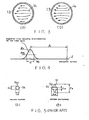
- Fig. 4 shows the relationship of the magnetic flux density distribution of a uniform horizontal deflection magnetic field on the tube axis Z with the distance from the centre of this distribution to the phosphor screen.
- the centre of the flux density distribution is defined as the position showing the maximum value B of the flux density distribution.
- the magnetic path length is defined a as the length determined by the width between the points where the value is half the maximum value B , and A as the distance from the centre M c of the flux density distribution to the face plate.
- the spot S 6a at the centre of the screen is shown in Fig. 6(a), and is core S .
- Fig. 6(b) when spot S5b having flares Sf is formed at the screen periphery, the dimension of the horizontal direction of the flares is F and the dimension of the vertical direction is F V . It was found that in this case the relationship shown in Fig. 7 exists between a/A and F V /F H .
- the practical range of a/A is from 0.1 to 0.4.
- the range of a/A is 0.2 to 0.3. The most ideal condition is obtained when a/A ⁇ 0.25, when the flares S f are circular and at their minimum size.
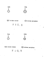
- Fig. 8 shows respectively the shapes S 8a and S 8b of the electron beam spot at the centre and at the periphery of the screen when a/A ⁇ 0.25.
- the focal point distances of the electron lenses of the electron guns are adjusted at the peripheral regions of the screen.
- Spot S 9b in Fig. 9(b) shows an example of the improvement which this makes possible.
- S 9a the shape of the spot at the centre of the screen is unchanged.
- the electron beam spot shape is further improved by the above construction.
- Convergence of the three electron beams over the entire surface of the face plate is further improved in the above construction of this invention by making the three electron beams generated from the electron guns practically parallel and providing a time delay in the times with which the signals that are applied to the three electron guns are mutually controlled.
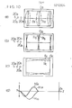
- Fig. 10(a) shows the patterns of red Ra, green Ga and blue Ba at the time, while the arrangement of 20B, 20G, 20R is the beam relative positions on the electron gun.
- the time at which the signal is applied to the second electron gun is delayed by a time ⁇ c with respect to the time at which the signal is applied to the first electron gun, and time at which the signal is applied to the third electron gun is delayed by a time ⁇ c with respect to the time at which the signal is applied to the second electron gun.
- ⁇ c is a convergence error at the centre area of the screen.
- Such residual convergence error has two types.
- One is a convergence error in the horizontal direction occuring at the upper and lower ends of the screen as shown in Fig. 10(b).
- the patterns Rb, Gb and Bb show the respective raster pattern for red, green and blue, when the beams 20B, 20G and 20R on the gun are arranged as shown in the figure.
- required delay time ⁇ D is given by : andlD increases with amounts proportional to the second power of the amount of the vertical deflection.
- the other type of the residual convergence error is a convergence error in the upper and lower direction occurring at the four corners of the screen as shown in Fig. 10(c), where the pattern Rc, Gc and Bc represent the respective raster pattern for red, green and blue.
- the pattern 20B, 20G and 20R shows the position of beams generated from the electron gun.
- the convergence error ⁇ V is given by: where Z is the tube axis of the colourcathode ray tube, Zo is the point of origin of the deflection, Zs is the position of the screen, X is a component in the horizontal direction in the beam path of which the electron beam is deflected towards the corner of the screen, H 10 is the intensity distribution of the vertical deflection field on the tube axis Z and H' I0 is a first differential coefficient relating to Z.
- H I2 is a parameter representing non-uniformity of the vertical deflection field
- H I2 >0 indicates a pin-cushion type field
- H ⁇ 0 indicates a barrel type field.
- HIO must be negative for the beam to be deflected to the upper right area of the screen(Fig. 10(d)).
- HI2 is the same sign as HIO, the sign of HI2 has to be the plus on the screen side and the minus on the electron gun side.
- non-uniformity of the vertical deflection magnetic field shows the barrel shape on the side of the electron gun and the pin-cushion shape on the side of the phosphor screen.
- the convergence error in the upper and lower direction at the upper right corner of the screen is reduced by the non-uniformity of the vertical deflection field.
- Such reduction is given at any corner of the screen by the non-uniformity field which is the barrel shape on the electron gun side and is the pin-cushion shape on the phosphor screen. Consequently, the second residual convergence error is easily reduced within the practically permissible range.
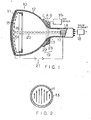
- Fig. 1 shows a 20 inch colour cathode ray tube with 90 degree deflection according to an embodiment of this invention.
- a glass envelope 10 is provided with a face plate 11, a funnel 12 integrally sealed to this face plate 11, and a neck 14 connected to the funnel.
- the inside face of face plate 11 is formed with a phosphor screen 15 for picture display.
- This phosphor screen is made up of a regular arrangement of phosphor dots or phosphor stripes that emit red, green and blue light.
- a shadow mask 16 is arranged facing and adjacent to screen 15. Shadow mask 16 normally comprises a thin iron plate of dome shape matching the internal shape of face plate 11, whose portion facing screen 15 is formed with a large number of apertures 16, so arranged that three electron beams 20 impinge correctly on the phosphors of the corresponding colour.
- An electron gun 17 that generates the three electron beams used for the three colours red, green, and blue is sealed into neck 14.
- the electron beams 20 are disposed in-line in the horizontal direction, i.e. the electron beams lie in the same horizontal plane. The arrangement is such that the electron beams are emitted parallel to each other with a mutual separation of about 6.6mm.
- the electron guns are integrated as a single unit comprising electron emitting cathodes and common electrodes of control, screen, focus and convergence cup electrodes. These are supplied with respective prescribed voltages.
- the potential of the high voltage electrodes as the convergence cup is usually ultra high potential (25kV).
- the phosphor screen and shadow mask are maintained at an equivalent potential of 25 kV, the same as the high voltage electrode, by a power source 21.
- a deflection device 19 is mounted in the vicinity of the region (usually called the "cone" 13 ) where neck 14 joins funnel 12.
- the picture signal is input between the cathodes and control electrodes corresponding to the respective electron beams.
- Deflection device 19 comprises a saddle shaped horizontal deflection coil 22 that generates a uniform magnetic field H as shown in Fig. 2. This constitutes the magnetic field that deflects electron beams 20 in the horizontal direction.
- the deflection coils are designed such that the half-width a of..the flux density distribution on the tube axis of the horizontal deflection magnetic field and the vertical deflection magnetic field is 0.25 times the distance A from the centre of the flux density distribution to the phosphor screen.
- Deflection device 19 is driven by deflection driver 19 1 .
- the horizontal width of the picture is about 400mm. If we assume that the horizontal deflection frequency is 15.75 kHz, the amount of mutual offset of the electron beam spots on the screen is 6.6mm, and the constant C is 0.75, the time delay of input of the picture signals for the various colours to the respective electron guns is about 0.8 microsecond.
- ⁇ D must be -0.4 microseconds.
- the design for the deflection field, the size of the colour cathode ray tube and so may require a change to this amount.
- the device produces pictures in which the distortion of beam spot core and flare is minimized at both of the centre and corner of the screen, bright and with high resolution at the whole screen.
- ⁇ c is a set constant.
- a convergence error 6 occurs in Fig. 10(b), in which red pattern Rb by beam 20R and blue pattern Bb by beam 20B are offset from green pattern Gb by beam 20G.
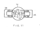
- Fig. 11 shows magnetic field generating means driven for correction of the convergence error and synchronized with the vertical deflection.
- pairs of pole pieces 30 and 31 are arranged outside the electron gun in the neck 14 to interpose the side beams 20R and 20B at the upper and lower sides thereof.
- a pair of magnetic plates 32 and 33 are arranged among the beams 20R, 20G and 20B.
- a pair of U-shaped magnetic field generators 34 and 35 with a coil are assembled symmetrically in the horizontal direction.
- the convergence error as shown in Figure 10b will be explained.
- the electron- beam 20R for red shifts to the left side and the electron beam 20B shifts to the right side at the end of the vertical axis of the screen.
- the magnetic field producing the force F is generated from generators 34 and 35, the coils of which are applied with parabolic- shaped current modulated and synchronised with the 2nd power of the vertical deflection amount.
- the current direction is selected so that the N pole and S pole distribution, as shown in the figure, is obtained.
- the current intensity is selected to minimise the convergence error on the screen.
- 26 inch 110 degree deflection tubes were used, while the other conditions were the same as in the preceding embodiment.
- a/A equal to 0.1 and a/A equal to 0.4, respectively.
- a/A was set to 0.2 to 0.3, performance was even further improved.
- the centres of the horizontal and vertical deflection magnetic fields were set at about 290 mm from the phosphor screen
- the position of the centre H c of the horiaontal deflection magnetic field is set at about 285 to 280 mm from the phosphor screen
- the position of the centre V of the vertical deflection magnetic field is set at about 295 to 300 mm from the phosphor screen.
- the centre H . of the horizontal deflection magnetic field is advanced from the centre V c of the vertical deflection magnetic field towards the phosphor screen 15 by an amount in the range 10 to 20 mm. It was found that this resulted in a further substantial improvement in the convergence accuracy attainable with three electron beams.
- a static convergence device is mounted on the electron gun side of the deflection coils and its hexapolar magnetic flux component leaks into the deflection magnetic field.
- the deflection field with hexapolar component compensation magnetic field as a result is, of course, also included in the uniform deflection magnetic field.
Landscapes
- Video Image Reproduction Devices For Color Tv Systems (AREA)
Applications Claiming Priority (2)
| Application Number | Priority Date | Filing Date | Title |
|---|---|---|---|
| JP180512/85 | 1985-08-19 | ||
| JP60180512A JPH0628140B2 (ja) | 1985-08-19 | 1985-08-19 | カラ−受像管装置 |
Publications (3)
| Publication Number | Publication Date |
|---|---|
| EP0212934A2 true EP0212934A2 (de) | 1987-03-04 |
| EP0212934A3 EP0212934A3 (en) | 1988-08-24 |
| EP0212934B1 EP0212934B1 (de) | 1992-04-22 |
Family
ID=16084545
Family Applications (1)
| Application Number | Title | Priority Date | Filing Date |
|---|---|---|---|
| EP86306233A Expired - Lifetime EP0212934B1 (de) | 1985-08-19 | 1986-08-12 | Farbkathodenstrahlröhre |
Country Status (6)
| Country | Link |
|---|---|
| US (1) | US4689525A (de) |
| EP (1) | EP0212934B1 (de) |
| JP (1) | JPH0628140B2 (de) |
| KR (1) | KR900002906B1 (de) |
| CN (1) | CN1035140C (de) |
| DE (1) | DE3684969D1 (de) |
Cited By (1)
| Publication number | Priority date | Publication date | Assignee | Title |
|---|---|---|---|---|
| US6534935B1 (en) | 1999-10-21 | 2003-03-18 | Matsushita Electric Industrial Co., Ltd. | Color CRT apparatus |
Families Citing this family (14)
| Publication number | Priority date | Publication date | Assignee | Title |
|---|---|---|---|---|
| KR890004872B1 (ko) * | 1985-05-21 | 1989-11-30 | 가부시끼 가이샤 도시바 | 칼라 수상관 장치 |
| US5901029A (en) * | 1988-03-28 | 1999-05-04 | Kabushiki Kaisha Toshiba | Method of degaussing a color cathode ray tube |
| JPH0379186A (ja) * | 1989-08-23 | 1991-04-04 | Mitsubishi Electric Corp | カラー陰極線管デイスプレイ装置 |
| JP3288695B2 (ja) * | 1990-07-17 | 2002-06-04 | 株式会社東芝 | カラー受像管を用いた表示装置 |
| US5248920A (en) * | 1992-10-13 | 1993-09-28 | Zenith Electronics Corporation | Cathode ray tube dynamic electron-optic eyebrow effect distortion correction |
| KR960028150A (ko) * | 1994-12-23 | 1996-07-22 | 구자홍 | 티브이(tv)의 코마에러 보정장치 |
| US6498443B2 (en) * | 2000-06-15 | 2002-12-24 | Matsushita Electric Industrial Co., Ltd. | Color TV tube apparatus and color display tube apparatus |
| US6831400B2 (en) | 2000-12-27 | 2004-12-14 | Kabushiki Kaisha Toshiba | Color cathode ray tube apparatus having auxiliary magnetic field generator |
| WO2005090654A1 (en) | 2004-03-16 | 2005-09-29 | University Of Delaware | Active and adaptive photochromic fibers,textiles and membranes |
| US8367639B2 (en) * | 2005-03-31 | 2013-02-05 | University Of Delaware | Hydrogels with covalent and noncovalent crosslinks |
| US7732427B2 (en) * | 2005-03-31 | 2010-06-08 | University Of Delaware | Multifunctional and biologically active matrices from multicomponent polymeric solutions |
| US7737131B2 (en) * | 2005-03-31 | 2010-06-15 | University Of Delaware | Multifunctional and biologically active matrices from multicomponent polymeric solutions |
| US8415325B2 (en) * | 2005-03-31 | 2013-04-09 | University Of Delaware | Cell-mediated delivery and targeted erosion of noncovalently crosslinked hydrogels |
| US8083983B2 (en) * | 2005-11-28 | 2011-12-27 | Rabolt John F | Method of solution preparation of polyolefin class polymers for electrospinning processing included |
Family Cites Families (5)
| Publication number | Priority date | Publication date | Assignee | Title |
|---|---|---|---|---|
| JPS4911462A (de) * | 1972-05-31 | 1974-01-31 | ||
| US3984723A (en) * | 1974-10-04 | 1976-10-05 | Rca Corporation | Display system utilizing beam shape correction |
| US4142131A (en) * | 1975-11-12 | 1979-02-27 | Hitachi, Ltd. | Color picture tube |
| JPS5820455B2 (ja) * | 1977-09-21 | 1983-04-23 | 株式会社日立製作所 | 偏向ヨ−ク |
| NL8006628A (nl) * | 1980-12-05 | 1982-07-01 | Philips Nv | Kathodestraalbuis - afbuigeenheid combinatie met hoog oplossend vermogen. |
-
1985
- 1985-08-19 JP JP60180512A patent/JPH0628140B2/ja not_active Expired - Lifetime
-
1986
- 1986-08-04 US US06/892,437 patent/US4689525A/en not_active Expired - Lifetime
- 1986-08-12 DE DE8686306233T patent/DE3684969D1/de not_active Expired - Lifetime
- 1986-08-12 EP EP86306233A patent/EP0212934B1/de not_active Expired - Lifetime
- 1986-08-18 KR KR1019860006848A patent/KR900002906B1/ko not_active Expired
- 1986-08-18 CN CN86105172A patent/CN1035140C/zh not_active Expired - Lifetime
Cited By (1)
| Publication number | Priority date | Publication date | Assignee | Title |
|---|---|---|---|---|
| US6534935B1 (en) | 1999-10-21 | 2003-03-18 | Matsushita Electric Industrial Co., Ltd. | Color CRT apparatus |
Also Published As
| Publication number | Publication date |
|---|---|
| EP0212934A3 (en) | 1988-08-24 |
| CN1035140C (zh) | 1997-06-11 |
| KR870002630A (ko) | 1987-04-06 |
| JPH0628140B2 (ja) | 1994-04-13 |
| KR900002906B1 (ko) | 1990-05-03 |
| EP0212934B1 (de) | 1992-04-22 |
| DE3684969D1 (de) | 1992-05-27 |
| JPS6243040A (ja) | 1987-02-25 |
| US4689525A (en) | 1987-08-25 |
| CN86105172A (zh) | 1987-02-18 |
Similar Documents
| Publication | Publication Date | Title |
|---|---|---|
| US4319163A (en) | Electron gun with deflection-synchronized astigmatic screen grid means | |
| EP0212934B1 (de) | Farbkathodenstrahlröhre | |
| US3800176A (en) | Self-converging color image display system | |
| CA1275684C (en) | Dynamically converging electron gun system | |
| US4057747A (en) | In-line plural beam color cathode ray tube having deflection defocus correcting elements | |
| CA1124304A (en) | Deflection yoke with a magnet for reducing sensitivity of convergence to yoke position | |
| US5412277A (en) | Dynamic off-axis defocusing correction for deflection lens CRT | |
| EP0292944B1 (de) | Farbkathodenstrahlapparat mit dynamischen Konvergenz-Mitteln | |
| CA1237464A (en) | Electron gun having a two piece screen grid electrode means | |
| EP0207394B1 (de) | Farbkathodenstrahlröhre | |
| EP0203765B1 (de) | Farbbildröhre | |
| US3639796A (en) | Color convergence system having elongated magnets perpendicular to plane of plural beams | |
| US4608515A (en) | Cathode-ray tube having a screen grid with asymmetric beam focusing means and refraction lens means formed therein | |
| US5339010A (en) | Color cathode-ray tube apparatus | |
| US4621215A (en) | Convergence system for a multi-beam electron gun | |
| US3188507A (en) | Beam penetration color cathode ray tube | |
| EP0198494B1 (de) | Farbbildgerät | |
| US4473773A (en) | In-line type electromagnetic focusing cathode-ray tube | |
| US3892996A (en) | Self-converging color television display system | |
| US5063326A (en) | Dynamic focus electron gun | |
| US3265915A (en) | Cathode ray tube | |
| JP2565863B2 (ja) | カラ−受像管装置 | |
| KR100252959B1 (ko) | 칼라 음극선관용 전자총 | |
| US2847600A (en) | Tri-color kinescope | |
| KR940008761B1 (ko) | 칼라 음극선관용 전자총 |
Legal Events
| Date | Code | Title | Description |
|---|---|---|---|
| PUAI | Public reference made under article 153(3) epc to a published international application that has entered the european phase |
Free format text: ORIGINAL CODE: 0009012 |
|
| 17P | Request for examination filed |
Effective date: 19860820 |
|
| AK | Designated contracting states |
Kind code of ref document: A2 Designated state(s): DE FR GB |
|
| PUAL | Search report despatched |
Free format text: ORIGINAL CODE: 0009013 |
|
| AK | Designated contracting states |
Kind code of ref document: A3 Designated state(s): DE FR GB |
|
| 17Q | First examination report despatched |
Effective date: 19900321 |
|
| GRAA | (expected) grant |
Free format text: ORIGINAL CODE: 0009210 |
|
| AK | Designated contracting states |
Kind code of ref document: B1 Designated state(s): DE FR GB |
|
| ET | Fr: translation filed | ||
| REF | Corresponds to: |
Ref document number: 3684969 Country of ref document: DE Date of ref document: 19920527 |
|
| PLBE | No opposition filed within time limit |
Free format text: ORIGINAL CODE: 0009261 |
|
| STAA | Information on the status of an ep patent application or granted ep patent |
Free format text: STATUS: NO OPPOSITION FILED WITHIN TIME LIMIT |
|
| 26N | No opposition filed | ||
| REG | Reference to a national code |
Ref country code: GB Ref legal event code: 746 Effective date: 19981026 |
|
| REG | Reference to a national code |
Ref country code: FR Ref legal event code: D6 |
|
| REG | Reference to a national code |
Ref country code: GB Ref legal event code: IF02 |
|
| PGFP | Annual fee paid to national office [announced via postgrant information from national office to epo] |
Ref country code: DE Payment date: 20050804 Year of fee payment: 20 |
|
| PGFP | Annual fee paid to national office [announced via postgrant information from national office to epo] |
Ref country code: FR Payment date: 20050809 Year of fee payment: 20 |
|
| PGFP | Annual fee paid to national office [announced via postgrant information from national office to epo] |
Ref country code: GB Payment date: 20050810 Year of fee payment: 20 |
|
| REG | Reference to a national code |
Ref country code: GB Ref legal event code: PE20 |
|
| PG25 | Lapsed in a contracting state [announced via postgrant information from national office to epo] |
Ref country code: GB Free format text: LAPSE BECAUSE OF EXPIRATION OF PROTECTION Effective date: 20060811 |