EP0211476A2 - Tauchausguss gebraucht beim Stranggiessen von Brammen - Google Patents
Tauchausguss gebraucht beim Stranggiessen von Brammen Download PDFInfo
- Publication number
- EP0211476A2 EP0211476A2 EP86303786A EP86303786A EP0211476A2 EP 0211476 A2 EP0211476 A2 EP 0211476A2 EP 86303786 A EP86303786 A EP 86303786A EP 86303786 A EP86303786 A EP 86303786A EP 0211476 A2 EP0211476 A2 EP 0211476A2
- Authority
- EP
- European Patent Office
- Prior art keywords
- molten metal
- outlet ports
- mold
- nozzle
- angle
- Prior art date
- Legal status (The legal status is an assumption and is not a legal conclusion. Google has not performed a legal analysis and makes no representation as to the accuracy of the status listed.)
- Granted
Links
Images
Classifications
-
- B—PERFORMING OPERATIONS; TRANSPORTING
- B22—CASTING; POWDER METALLURGY
- B22D—CASTING OF METALS; CASTING OF OTHER SUBSTANCES BY THE SAME PROCESSES OR DEVICES
- B22D11/00—Continuous casting of metals, i.e. casting in indefinite lengths
- B22D11/10—Supplying or treating molten metal
-
- B—PERFORMING OPERATIONS; TRANSPORTING
- B22—CASTING; POWDER METALLURGY
- B22D—CASTING OF METALS; CASTING OF OTHER SUBSTANCES BY THE SAME PROCESSES OR DEVICES
- B22D41/00—Casting melt-holding vessels, e.g. ladles, tundishes, cups or the like
- B22D41/50—Pouring-nozzles
Definitions
- This invention relates to a submerged nozzle for use in the continuous casting of metal slabs.
- the continuous casting of slabs, and particularly stainless steel slabs is typically accomplished by using a flow-through continuous casting mold having a rectangular internal mold cavity.
- a submerged nozzle is used for introducing molten metal below the surface of a molten metal pool which is formed in the continuous casting mold.
- bifurcated submerged nozzles are used; however, these cause problems in the casting operation, particularly in the casting of stainless steel slabs.
- titanium for stabilization purposes.
- the titanium is added in the tap ladle prior to the continuous casting operation.
- a portion of the titanium reacts with the nitrogen dissolved in the metal for form small, insoluble nitride particles in the molten metal introduced to the continuous casting mold.
- These nitride particles tend to coalesce and collect in the continuous casting mold by floating on the surface of the molten metal in the mold or accumulating as entrapped particles in the solidified metal portion of the continuous casting.
- These nitrides result in objectionable titanium streaks on the surface of the hot-rolled band produced from the continuously cast slab. This may be sufficiently severe to cause rejection and ultimate scrapping of the metal.
- a more specific object of the invention is to provide a submerged nozzle for continuous casting operations that may be used in the casting of austenitic or ferritic grades of stainless steel in the form of slabs over a wide range of sizes.
- Yet another more specific object of the invention is to provide a submerged nozzle for continuous casting applications in the casting of austenitic or ferritic grades of stainless steel wherein, during the initial filling of the mold, metal is provided at a rate sufficient to reduce the filling time of the mold and yet not cause harmful flaring and splashing onto the mold walls and, during subsequent casting operations, the metal flow pattern in the mold is such that the incoming and hottest metal initially flows to the surface to contact the mold flux so that there is rapid melting of the flux, heat extraction from the metal, and removal of nonmetallics entrained in the metal. The nonmetallics are removed by absorption in the molten flux or, if insoluble, the flow provides for a more uniform distribution of the entrained material, such as titanium nitrides, over the entire cross-sectional area of the cast slab.
- the entrained material such as titanium nitrides
- a nozzle comprising a tube having an upper end portion adapted for connection to a source of molten metal to be introduced to a continuous casting mold and a lower end that is closed. Adjacent the lower end there are two molten metal outlet ports of equal diameter and in opposed relation with each being axially inclined upwardly at an angle e of 12 to 17°, preferably at an angle of about 15°.
- molten metal outlet ports with the cross-sectional size of each being larger than that of each of said two molten metal outlet ports of equal diameter are positioned adjacent said lower end of the nozzle in diametrically opposed pairs with each pair being non-radial at an included anqle Q of 28 to 32°, preferably at an included angle of approximately 30°.
- These ports are also inclined upwardly at an angle of 12 to 17°, preferably at an angle of about 15°.
- all of the molten metal outlet ports are inclined upwardly at substantially the same angle.
- the two metal outlet ports of equal diameter face one of the relatively longer mold walls and each pair of the additional larger outlet ports face one of the mold walls of relatively shorter length.
- the pairs of relatively larger molten metal outlet ports are of elongated or generally elliptical cross section.
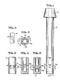
- FIG. 1 there is shown in Figure 1 thereof a nozzle in accordance with the invention designated generally as 10.
- the nozzle is of elongated tubular construction, having at an upper portion thereof a collar 12 which is adapted for connection in the well known manner to a source of molten metal (not shown).
- the opposite end of the nozzle 10 designated as 14 is closed. Adjacent the lower end 14 are two opposed metal outlet passages 16 and 16a. These passages are inclined upwardly at an angle-0-of approximatgely 15°.
- Each pair 18 and 18a of outlet ports or passages are oriented non-radially at an included angle of approximately 30°.
- included angle 9 is symmetrical about a first centre line, and preferably each pair of ports are symmetrical with the other pair of ports about a second centre line.
- the cross section of passages 18 and 18a are elongated or generally elliptical in the direction of the longitudinal axis of the nozzle 10.
- the nozzle In the operation of the nozzle in a continuous casting operation, as earlier described, the nozzle is positioned within a rectangular mold with the two molten metal outlet ports of equal diameter (16 and 16a) each facing one of the relatively longer mold walls (not shown) and each pair of the outlet ports of relatively larger cross section (18 and 18a) facing one of the mold walls of relatively shorter length.
- the outlet ports (16 and 16a) that impinge at the slab or mold mid-width portion are of reduced size to limit the impingement of the stream of hot metal introduced to the mold at this area thereof. This avoids remelting of the solidified casting shell which may result in longitudinal surface cracks or in extreme cases to a breakout of molten metal through this solidified shell portion.
- the flow characteristics are uniform, smooth, and repeatable, which allows the mold to be filled at a highly controlled rate over that obtained with the use of conventional bifurcated nozzles. This, therefore, eliminated the need to use splash cans in the mold during start-up. After the molten metal in the mold covers the nozzle ports, a quiescent metal surface is obtained to which application of mold powder may be made without concern for it being drawn down into the molten metal.
- the bifurcated nozzles had two molten metal outlet ports adjacent the lower closed end of the nozzle. The ports were diametrically opposed and each faced one of the mold walls of relatively shorter length.
- the bifurcated nozzles had ports of either 1.75 or 1.563 inches (4.445 or 3.970 cm) inclined upwardly at 20° or 2.0 inches (5.08 cm) inclined upwardly at 15°.
- the nozzle of the present invention had two metal outlet ports of equal diameter of .375 inch (.952 cm) and two pairs of diametrically opposed elliptical outlet ports of larger cross-sectional size. These ports were elliptical in the direction of the axis of nozzle.
- the elliptical ports had .5 inch (1.27 cm) radii on about 1.0 inch (2.54 cm) centres.
- the equal diameter ports were inclined upwardly at 15°.
- the two pairs of outlet ports were oriented non-radially at an included angle of 30° and were also inclined upwardly at about 15°.
- the two ports of equal diameter were positioned with each facing one of the relatively longer walls of the mold. Each pair of additional ports faced one of the walls of relatively shorter length.
- Each nozzle was made of graphitized alumina.
- Example II Using the same nozzles as set forth in Example I, the improvement in first slab quality is shown for T304 steel in hot-rolled band coil form in Table II.
- the first slab quality for 6 hot-rolled band coils of T409#4l3 was also determined for the nozzle of the present invention of Example I. As for all defects, 5 coils were very good and had no defects, only 1 coil had lap defects, and no coils had TiN streak defects. These coils were 100% free of TiN streak defects and were 83.3% free of laps.
Landscapes
- Engineering & Computer Science (AREA)
- Mechanical Engineering (AREA)
- Casting Support Devices, Ladles, And Melt Control Thereby (AREA)
- Continuous Casting (AREA)
Applications Claiming Priority (2)
| Application Number | Priority Date | Filing Date | Title |
|---|---|---|---|
| US760446 | 1985-07-30 | ||
| US06/760,446 US4662546A (en) | 1985-07-30 | 1985-07-30 | Submerged nozzle for use in the continuous casting of slabs |
Publications (3)
| Publication Number | Publication Date |
|---|---|
| EP0211476A2 true EP0211476A2 (de) | 1987-02-25 |
| EP0211476A3 EP0211476A3 (en) | 1988-01-20 |
| EP0211476B1 EP0211476B1 (de) | 1990-03-14 |
Family
ID=25059140
Family Applications (1)
| Application Number | Title | Priority Date | Filing Date |
|---|---|---|---|
| EP86303786A Expired - Lifetime EP0211476B1 (de) | 1985-07-30 | 1986-05-19 | Tauchausguss gebraucht beim Stranggiessen von Brammen |
Country Status (6)
| Country | Link |
|---|---|
| US (1) | US4662546A (de) |
| EP (1) | EP0211476B1 (de) |
| JP (1) | JPH0675755B2 (de) |
| KR (1) | KR920001707B1 (de) |
| CA (1) | CA1243188A (de) |
| DE (1) | DE3669448D1 (de) |
Cited By (1)
| Publication number | Priority date | Publication date | Assignee | Title |
|---|---|---|---|---|
| EP0473499A1 (de) * | 1990-08-30 | 1992-03-04 | Sollac | Verfahren und Einrichtung für ein Strahlschutzrohr beim Stranggiessen |
Families Citing this family (6)
| Publication number | Priority date | Publication date | Assignee | Title |
|---|---|---|---|---|
| DE3623660A1 (de) * | 1986-07-12 | 1988-01-14 | Thyssen Stahl Ag | Feuerfestes giessrohr |
| US5280577A (en) * | 1988-01-19 | 1994-01-18 | E. I. Du Pont De Nemours & Co., Inc. | Character generation using graphical primitives |
| DE3811751A1 (de) * | 1988-04-08 | 1989-10-19 | Schloemann Siemag Ag | Tauchgiessrohr zum einleiten von metallschmelze in eine metallbandgiesskokille |
| JP2547771Y2 (ja) * | 1990-11-15 | 1997-09-17 | 川崎炉材株式会社 | 連続鋳造用浸漬ノズル |
| US5227078A (en) * | 1992-05-20 | 1993-07-13 | Reynolds Metals Company | Flow-vectored downspout assembly and method for using same |
| CN111036891A (zh) * | 2019-11-29 | 2020-04-21 | 浙江科宇金属材料有限公司 | 垂直铸造用浇管 |
Family Cites Families (9)
| Publication number | Priority date | Publication date | Assignee | Title |
|---|---|---|---|---|
| US3322347A (en) * | 1965-08-02 | 1967-05-30 | Carroll L Pierce | Dual purpose rotary mower washer and sprinkler device |
| US3578064A (en) * | 1968-11-26 | 1971-05-11 | Inland Steel Co | Continuous casting apparatus |
| JPS526926B1 (de) * | 1968-11-26 | 1977-02-25 | ||
| US3517726A (en) * | 1969-08-04 | 1970-06-30 | Inland Steel Co | Method of introducing molten metal into a continuous casting mold |
| US3934638A (en) * | 1971-02-08 | 1976-01-27 | Inland Steel Company | Continuous casting process |
| GB1472449A (en) * | 1973-09-04 | 1977-05-04 | Sumitomo Metal Ind | Nozzle for a continuous metal casting tundish |
| JPS5314650Y2 (de) * | 1974-03-30 | 1978-04-18 | ||
| US4202397A (en) * | 1975-01-20 | 1980-05-13 | Bethlehem Steel Corporation | Method of continuously casting molten metal |
| JPS533210U (de) * | 1976-06-25 | 1978-01-12 |
-
1985
- 1985-07-30 US US06/760,446 patent/US4662546A/en not_active Expired - Lifetime
-
1986
- 1986-03-11 CA CA000503769A patent/CA1243188A/en not_active Expired
- 1986-04-16 JP JP61087854A patent/JPH0675755B2/ja not_active Expired - Lifetime
- 1986-04-30 KR KR1019860003364A patent/KR920001707B1/ko not_active Expired
- 1986-05-19 DE DE8686303786T patent/DE3669448D1/de not_active Expired - Fee Related
- 1986-05-19 EP EP86303786A patent/EP0211476B1/de not_active Expired - Lifetime
Cited By (2)
| Publication number | Priority date | Publication date | Assignee | Title |
|---|---|---|---|---|
| EP0473499A1 (de) * | 1990-08-30 | 1992-03-04 | Sollac | Verfahren und Einrichtung für ein Strahlschutzrohr beim Stranggiessen |
| FR2666257A1 (fr) * | 1990-08-30 | 1992-03-06 | Lorraine Laminage | Tube protecteur de jet d'une installation de coulee continue et procede en comportant application. |
Also Published As
| Publication number | Publication date |
|---|---|
| KR920001707B1 (ko) | 1992-02-24 |
| EP0211476A3 (en) | 1988-01-20 |
| KR870000981A (ko) | 1987-03-10 |
| EP0211476B1 (de) | 1990-03-14 |
| US4662546A (en) | 1987-05-05 |
| JPH0675755B2 (ja) | 1994-09-28 |
| DE3669448D1 (de) | 1990-04-19 |
| CA1243188A (en) | 1988-10-18 |
| JPS6228052A (ja) | 1987-02-06 |
Similar Documents
| Publication | Publication Date | Title |
|---|---|---|
| US4819840A (en) | Refractory submerged pouring nozzle | |
| EP0925132B1 (de) | Tauchgiessrohr zum stranggiessen von dünnbrammen | |
| EP0662021B1 (de) | Feuerfester artikel zur verhinderung der wirbelung in metallurgischen gefässen | |
| US3517726A (en) | Method of introducing molten metal into a continuous casting mold | |
| US5716538A (en) | Discharge nozzle for continuous casting | |
| EP0211476B1 (de) | Tauchausguss gebraucht beim Stranggiessen von Brammen | |
| GB2162103A (en) | Improvements in continuous casting nozzles | |
| CA1128279A (en) | Method and apparatus for continuous metal casting | |
| US4202397A (en) | Method of continuously casting molten metal | |
| JP2002501438A (ja) | スラブを製造するための方法および装置 | |
| Szekeres | Review of strand casting factors affecting steel product cleanliness | |
| JPS61266155A (ja) | クラツド鋳片の連続鋳造方法及びその装置 | |
| JPH04220148A (ja) | 溶湯供給ノズル | |
| JPS57124558A (en) | Continuous casting method | |
| JPS63303665A (ja) | 連続鋳造浸漬ノズル | |
| JPS60127051A (ja) | 連続鋳造法 | |
| JPS62254965A (ja) | 注湯取鍋 | |
| KR100485404B1 (ko) | 박형슬라브를연속주조하기위한부분침수노즐 | |
| FI61138B (fi) | Foerfarande foer kontinuerlig gjutning av staol | |
| JPH0641950U (ja) | 連続鋳造用浸漬ノズル | |
| JPS6353901B2 (de) | ||
| SU1046005A1 (ru) | Погружаемый стакан дл непрерывного лить сортовых заготовок | |
| SU1061917A1 (ru) | Устройство дл подвода металла | |
| RU2066591C1 (ru) | Устройство для поточного вакуумирования металла при непрерывной разливке | |
| RU1806040C (ru) | Способ непрерывной разливки металлов |
Legal Events
| Date | Code | Title | Description |
|---|---|---|---|
| PUAI | Public reference made under article 153(3) epc to a published international application that has entered the european phase |
Free format text: ORIGINAL CODE: 0009012 |
|
| AK | Designated contracting states |
Kind code of ref document: A2 Designated state(s): DE FR GB SE |
|
| PUAL | Search report despatched |
Free format text: ORIGINAL CODE: 0009013 |
|
| AK | Designated contracting states |
Kind code of ref document: A3 Designated state(s): DE FR GB SE |
|
| 17P | Request for examination filed |
Effective date: 19880328 |
|
| 17Q | First examination report despatched |
Effective date: 19880817 |
|
| GRAA | (expected) grant |
Free format text: ORIGINAL CODE: 0009210 |
|
| AK | Designated contracting states |
Kind code of ref document: B1 Designated state(s): DE FR GB SE |
|
| REF | Corresponds to: |
Ref document number: 3669448 Country of ref document: DE Date of ref document: 19900419 |
|
| ET | Fr: translation filed | ||
| PLBE | No opposition filed within time limit |
Free format text: ORIGINAL CODE: 0009261 |
|
| STAA | Information on the status of an ep patent application or granted ep patent |
Free format text: STATUS: NO OPPOSITION FILED WITHIN TIME LIMIT |
|
| 26N | No opposition filed | ||
| PGFP | Annual fee paid to national office [announced via postgrant information from national office to epo] |
Ref country code: FR Payment date: 19930409 Year of fee payment: 8 |
|
| PGFP | Annual fee paid to national office [announced via postgrant information from national office to epo] |
Ref country code: DE Payment date: 19930414 Year of fee payment: 8 |
|
| PGFP | Annual fee paid to national office [announced via postgrant information from national office to epo] |
Ref country code: SE Payment date: 19930415 Year of fee payment: 8 |
|
| PGFP | Annual fee paid to national office [announced via postgrant information from national office to epo] |
Ref country code: GB Payment date: 19930430 Year of fee payment: 8 |
|
| PG25 | Lapsed in a contracting state [announced via postgrant information from national office to epo] |
Ref country code: GB Effective date: 19940519 |
|
| PG25 | Lapsed in a contracting state [announced via postgrant information from national office to epo] |
Ref country code: SE Effective date: 19940520 |
|
| GBPC | Gb: european patent ceased through non-payment of renewal fee |
Effective date: 19940519 |
|
| EUG | Se: european patent has lapsed |
Ref document number: 86303786.7 Effective date: 19941210 |
|
| PG25 | Lapsed in a contracting state [announced via postgrant information from national office to epo] |
Ref country code: FR Effective date: 19950131 |
|
| PG25 | Lapsed in a contracting state [announced via postgrant information from national office to epo] |
Ref country code: DE Effective date: 19950201 |
|
| EUG | Se: european patent has lapsed |
Ref document number: 86303786.7 |
|
| REG | Reference to a national code |
Ref country code: FR Ref legal event code: ST |