EP0211418B1 - Wäschetrockner mit Kondensationseinrichtung - Google Patents
Wäschetrockner mit Kondensationseinrichtung Download PDFInfo
- Publication number
- EP0211418B1 EP0211418B1 EP86110662A EP86110662A EP0211418B1 EP 0211418 B1 EP0211418 B1 EP 0211418B1 EP 86110662 A EP86110662 A EP 86110662A EP 86110662 A EP86110662 A EP 86110662A EP 0211418 B1 EP0211418 B1 EP 0211418B1
- Authority
- EP
- European Patent Office
- Prior art keywords
- machine
- condenser unit
- deflector element
- cooling air
- receptacle
- Prior art date
- Legal status (The legal status is an assumption and is not a legal conclusion. Google has not performed a legal analysis and makes no representation as to the accuracy of the status listed.)
- Expired - Lifetime
Links
- 238000001816 cooling Methods 0.000 claims abstract description 15
- 238000001035 drying Methods 0.000 claims abstract description 6
- 230000004308 accommodation Effects 0.000 claims abstract description 4
- 238000004891 communication Methods 0.000 claims description 2
- 238000010276 construction Methods 0.000 abstract description 5
- XLYOFNOQVPJJNP-UHFFFAOYSA-N water Substances O XLYOFNOQVPJJNP-UHFFFAOYSA-N 0.000 description 3
- 230000005484 gravity Effects 0.000 description 1
- 238000004900 laundering Methods 0.000 description 1
- 238000010412 laundry washing Methods 0.000 description 1
- 239000007788 liquid Substances 0.000 description 1
- 238000004519 manufacturing process Methods 0.000 description 1
- 238000012986 modification Methods 0.000 description 1
- 230000004048 modification Effects 0.000 description 1
- 238000005192 partition Methods 0.000 description 1
- 238000010408 sweeping Methods 0.000 description 1
Images


Classifications
-
- D—TEXTILES; PAPER
- D06—TREATMENT OF TEXTILES OR THE LIKE; LAUNDERING; FLEXIBLE MATERIALS NOT OTHERWISE PROVIDED FOR
- D06F—LAUNDERING, DRYING, IRONING, PRESSING OR FOLDING TEXTILE ARTICLES
- D06F58/00—Domestic laundry dryers
- D06F58/20—General details of domestic laundry dryers
- D06F58/24—Condensing arrangements
Definitions
- the present invention relates to a condenser laundry dryer, particularly of the domestic type having a rotating drum, in which the discharge flow of the cooling air of the condenser unit may selectively be directed along different discharge flowpaths from the machine, depending on the location of the condensate collector receptacle, which in the laundry dryer according to the invention may be positioned in an upper or a lower portion of the machine.
- the condensed water is collected in a receptacle removably accommodated in the interior of the machine so that it can be emptied when the collected water attains a maximum filling level.
- the condensate collector receptacle is usually of the open-top type. In the more economic models of laundry dryers, it is usually placed directly underneath the condenser unit so as to be filled with the condensate flowing from the surfaces of the condenser by the action of gravity. In the more sophisticated models of laundry dryers, (see eg. GB-A-2 115 126) the receptacle is frequently placed at a more convenient location in an upper portion of the machine so as to be removable therefrom. In this case, the condensed water accumulates in a collector disposed below the condenser and is conveyed therefrom to the collector receptacle by means of a transfer conduit connected to a centrifugal pump.
- the two basic types of dryers arc provided with different discharge flowpaths for the cooling air, resulting in an uneconomical diversification in the manufacture of dryers conforming to one or the other basic type.
- a laundry dryer the construction of which is standardized as far as possible for the two basic types of dryers for thus enabling the condensate collector receptacle to be selectively positioned in a lower portion or an upper portion of the machine, so that the desired dryer model can be obtained by carrying out simple modifications during the final stage of assembly.
- a laundry dryer of this construction would also be more readily adaptable to the composition of so-called laundering columns, in which case the laundry dryer would be placed on top of a laundry washing machine, so that, to be readily accessible, the condensate collector receptacle would necessarily have to be located in the lower portion of the machine.
- a laundry dryer having a rotatable drum, with circulation of the drying air in a closed circuit, and an open cooling air circuit for a condenser
- said dryer being provided with a removable condensate collector receptacle and a condenser unit housed in a box-shaped container formed with inlet and outlet openings for the condensing air
- a deflector element mounted on the outlet opening of the box-shaped container is adapted to selectively assume one of two positions in a first of which it cooperates with the walls of the dryer and with baffles integrally formed with the box-shaped container to form a conduit for the discharge of the condensing air to the exterior, and in the second of which it forms a partition defining a chamber for the accomodation of the removable receptacle below the condenser unit, and simultaneously establishes communication of the condenser unit with the interior of the hous ing of the dryer.
- the laundry dryer 10 is of the type having a rotatable drum (not shown) and includes an air-cooled condenser unit 11 housed in a box-shaped container 12 fixedly mounted in a lower portion of the dryer.
- the cooling air for condenser unit 11 is aspirated by means of a fan 13 through an opening 14 formed in a bottom portion 15 of a front wall 30 of the dryer.
- the interior rim of opening 14 is extended towards the interior of the machine so as to permit the respective part of bottom portion 15 to be received in a connector element 16 to thus define a flowpath for the air aspirated by fan 13.
- Fan 13 is rotated by a motor 17 of the machine so as to convey the aspirated air through the drying air condenser unit 11 and to expel it from box-shaped housing 12 through at least one outlet opening 18 formed in the housing opposite an inlet opening 19 thereof.
- Box-shaped housing 12 is integrally formed with a lower baffle 20 delimiting an area below condenser unit 11.
- baffle 20 and 21 and the bottom of box-shaped container 12 cooperate with the bottom 22 of the machine to define a chamber 31 communicating with the remainder of the dryer 10 through a passage 24 (fig. 3) extending between cooling air outlet opening 18 and a sidewall 23 of the machine 10.
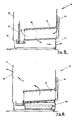
- the above described machine is adapted to accommodate a condensate collector receptacle 25 selectively in chamber 31 underneath condenser unit 11 (figs. 3, 6) or in an upper portion of dryer 10, as diagrammatically shown in fig. 2.
- a deflector element 26 having a substantially L-shaped cross-section and extending over the full length of opening 18 between front wall 30 of the machine and lateral baffle 21 of box-shaped container 12.
- Deflector element 26 may be secured to the upper boundary of outlet opening 18 by means of threaded fasteners or in a snap fit, and in engagement with the adjacent sidewall 23 of the machine, as shown in fig. 2, so as to deflect the cooling air towards chamber 31 underneath container 12, from where the air escapes to the exterior of machine 10 through openings 27 in the base of the housing.
- This solution offers the additional advantage that the cooling air escaping from condenser unit 11 at a temperature which is always lower than that of the drying drum is prevented from sweeping the walls of the drum and from thereby impairing the efficiency of the drying process, instead of which it is directly discharged from the machine.
- deflector element 26 For obtaining a laundry dryer with receptacle 25 accommodated in chamber 31, the same deflector element 26 is secured to the lower rim of outlet opening 18 and in contact with sidewall 23 of the machine in the position depicted in fig. 3. In this position, deflector element 26 deflects the air escaping from outlet opening 18 upwards into the free space in the interior of the machine, from which it escapes through openings 28 formed in the rear wall 29 of the machine.
- the dryer has of course to be provided with the known components required for its operation in the respective configuration.
- box-shaped container 12 with a lower opening (not shown in the drawings), which in the configuration with receptacle 25 in the lower position permits the condensate to flow into a hopper 40 communicating with receptacle 25 (figs. 3, 6).
Landscapes
- Engineering & Computer Science (AREA)
- Textile Engineering (AREA)
- Detail Structures Of Washing Machines And Dryers (AREA)
- Medicines Containing Material From Animals Or Micro-Organisms (AREA)
- Drying Of Solid Materials (AREA)
- Accessory Of Washing/Drying Machine, Commercial Washing/Drying Machine, Other Washing/Drying Machine (AREA)
Claims (4)
- Wäschetrockner (10) mit einer drehbaren Trommel mit Umwälzung von Trocknungsluft in einem geschlossenen Kreislauf und mit einem offenen Kühlluftkreislauf für einen Kondensator, der mit einem entnehmbar angebrachten Kondensatsammelbehälter (25) und einer Kondensatoreinheit (11) versehen ist, die in einem kastenförmigen Behälter (12) untergebracht ist, der mit Einlaß- und Auslaßöffnungen (19, 18) für die Kondensatorluft versehen ist,
dadurch gekennzeichnet,
daß ein Ablenkelement (26), das an der Auslaßöffnung (18) des kastenförmigen Behälters (12) montiert ist, dazu eingerichtet ist, wahlweise eine von zwei Stellungen einzunehmen, in deren erster es mit den Wänden der Maschine (10) und mit Prallplatten (20, 21) zusammenwirkt, die integral mit dem kastenförmigen Behälter (12) ausgebildet sind, um einen Strömungsweg für den Auslaß der Kondensatorluft aus der Maschine nach außen auszubilden, und in deren zweiter es eine Kammer (31) unterhalb der Kondensatoreinheit (11) für die Unterbringung des entnehmbaren Behälters (25) begrenzt, wobei es gleichzeitig eine Verbindung der Kondensatoreinheit (11) mit dem Innenraum des Gehäuses der Maschine (10) herstellt. - Wäschetrockner nach Anspruch 1,
dadurch gekennzeichnet,
daß in der ersten Position das Ablenkelement (26) längs des oberen Randes der Auslaßöffnung (18) montiert ist, um mit einer Seitenwand (23) und dem Boden (22) der Maschine (10) und mit einer seitlichen Prallplatte (21) und einer unteren Prallplatte (20) zusammenzuwirken, die sich jeweils in Berührung mit der Seitenwand (23) und dem Boden (22) der Maschine (10) erstrecken, um somit einen Auslaßströmungsweg für die Kühlluft gegen Aulaßöffnungen (27) auszubilden, die in der Kammer (31) vorgesehen sind. - Wäschetrockner nach Anspruch 1,
dadurch gekennzeichnet,
daß in der zweiten Position das Ablenkelement (26) längs des unteren Randes der Auslaßöffnung (18) angebracht ist, um die Kühlluftströmung gegen Auslaßöffnungen (28) zu richten die in der Rückwand (29) der Maschine ausgebildet sind, und um zusammen mit der Seitenwand (23), dem Boden (22) und den Prallplatten (20, 21) eine geschlossene Kammer (31) unterhalb des kastenförmigen Behälters (12) der Kondensatoreinheit für die Unterbringung des entnehmbaren Kondensatsammelbehälters (25) auszubilden. - Wäschetrockner nach einem der vorhergehenden Ansprüche,
dadurch gekennzeichnet,
daß das Ablenkelement (26) einen im wesentlichen L-förmigen Querschnitt hat und an einem seiner Enden mit Hil fe geschraubter Befestigungseinrichtungen oder mit einer Schnappverbindung am oberen oder unteren Rand der Kühlluftauslaßöffnung (18) derart befestigt ist, daß sein anderes Ende die benachbarte Seitenwand (23) der Maschine (10) berührt.
Priority Applications (1)
| Application Number | Priority Date | Filing Date | Title |
|---|---|---|---|
| AT86110662T ATE62285T1 (de) | 1985-08-02 | 1986-08-01 | Waeschetrockner mit kondensationseinrichtung. |
Applications Claiming Priority (2)
| Application Number | Priority Date | Filing Date | Title |
|---|---|---|---|
| IT3405285U | 1985-08-02 | ||
| IT8534052U IT209164Z2 (it) | 1985-08-02 | 1985-08-02 | Asciugabiancheria a condensazione. |
Publications (3)
| Publication Number | Publication Date |
|---|---|
| EP0211418A2 EP0211418A2 (de) | 1987-02-25 |
| EP0211418A3 EP0211418A3 (en) | 1988-01-27 |
| EP0211418B1 true EP0211418B1 (de) | 1991-04-03 |
Family
ID=11239054
Family Applications (1)
| Application Number | Title | Priority Date | Filing Date |
|---|---|---|---|
| EP86110662A Expired - Lifetime EP0211418B1 (de) | 1985-08-02 | 1986-08-01 | Wäschetrockner mit Kondensationseinrichtung |
Country Status (4)
| Country | Link |
|---|---|
| EP (1) | EP0211418B1 (de) |
| AT (1) | ATE62285T1 (de) |
| DE (1) | DE3678506D1 (de) |
| IT (1) | IT209164Z2 (de) |
Cited By (4)
| Publication number | Priority date | Publication date | Assignee | Title |
|---|---|---|---|---|
| US8155508B2 (en) | 2006-01-12 | 2012-04-10 | Dyson Technology Limited | Drying apparatus |
| US8341853B2 (en) | 2005-07-30 | 2013-01-01 | Dyson Technology Limited | Drying apparatus |
| US8347521B2 (en) | 2005-07-30 | 2013-01-08 | Dyson Technology Limited | Drying apparatus |
| US8490291B2 (en) | 2005-07-30 | 2013-07-23 | Dyson Technology Limited | Dryer |
Families Citing this family (9)
| Publication number | Priority date | Publication date | Assignee | Title |
|---|---|---|---|---|
| DE9210477U1 (de) * | 1992-08-05 | 1992-09-24 | Bosch-Siemens Hausgeräte GmbH, 8000 München | Wäschetrockner mit Kühlerblock |
| DE19960217C2 (de) * | 1999-12-14 | 2003-04-10 | Whirlpool Co | Kondensations-Wäschetrockner mit Wärmetauscher und Kondensat-Auffangeinrichtung |
| KR100487759B1 (ko) * | 2003-08-13 | 2005-05-06 | 엘지전자 주식회사 | 의류건조기의 냉각공기 흡입구조 |
| EP1555342B1 (de) * | 2003-12-19 | 2017-08-02 | LG Electronics, Inc. | Ein Wäschetrockner und eine Lufteinlasstruktur dafür |
| GB2434160A (en) | 2006-01-12 | 2007-07-18 | Dyson Technology Ltd | Drying apparatus |
| CN101684606B (zh) * | 2008-09-26 | 2011-11-09 | 博西华电器(江苏)有限公司 | 家用干衣设备 |
| EP2458072A1 (de) | 2010-11-29 | 2012-05-30 | Electrolux Home Products Corporation N.V. | Wäschetrockner |
| EP2458074A1 (de) * | 2010-11-29 | 2012-05-30 | Electrolux Home Products Corporation N.V. | Wärmepumpenwäschetrockner |
| EP3234254B1 (de) * | 2014-12-16 | 2023-06-07 | Electrolux Appliances Aktiebolag | Wäschebehandlungsvorrichtung mit wärmetauscher und kondensatsammler |
Family Cites Families (4)
| Publication number | Priority date | Publication date | Assignee | Title |
|---|---|---|---|---|
| US2742708A (en) * | 1952-07-12 | 1956-04-24 | Gen Motors Corp | Domestic appliance |
| DE8017935U1 (de) * | 1980-07-04 | 1980-10-02 | Sueddeutsche Kuehlerfabrik Julius Fr. Behr Gmbh & Co Kg, 7000 Stuttgart | Luftgekühlter Kondensations-Wärmetrockner |
| DE8123353U1 (de) * | 1981-08-08 | 1982-12-09 | G. Bauknecht Gmbh, 7000 Stuttgart | Waeschetrockner mit kondensationseinrichtung |
| DE3204412C2 (de) * | 1982-02-09 | 1986-07-10 | Bosch-Siemens Hausgeräte GmbH, 7000 Stuttgart | Haushalt-Wäschetrockner mit einem oben angeordneten Kondensat-Sammelbehälter |
-
1985
- 1985-08-02 IT IT8534052U patent/IT209164Z2/it active
-
1986
- 1986-08-01 AT AT86110662T patent/ATE62285T1/de active
- 1986-08-01 DE DE8686110662T patent/DE3678506D1/de not_active Expired - Fee Related
- 1986-08-01 EP EP86110662A patent/EP0211418B1/de not_active Expired - Lifetime
Cited By (4)
| Publication number | Priority date | Publication date | Assignee | Title |
|---|---|---|---|---|
| US8341853B2 (en) | 2005-07-30 | 2013-01-01 | Dyson Technology Limited | Drying apparatus |
| US8347521B2 (en) | 2005-07-30 | 2013-01-08 | Dyson Technology Limited | Drying apparatus |
| US8490291B2 (en) | 2005-07-30 | 2013-07-23 | Dyson Technology Limited | Dryer |
| US8155508B2 (en) | 2006-01-12 | 2012-04-10 | Dyson Technology Limited | Drying apparatus |
Also Published As
| Publication number | Publication date |
|---|---|
| IT209164Z2 (it) | 1988-09-16 |
| DE3678506D1 (de) | 1991-05-08 |
| ATE62285T1 (de) | 1991-04-15 |
| EP0211418A3 (en) | 1988-01-27 |
| EP0211418A2 (de) | 1987-02-25 |
| IT8534052V0 (it) | 1985-08-02 |
Similar Documents
| Publication | Publication Date | Title |
|---|---|---|
| EP0211418B1 (de) | Wäschetrockner mit Kondensationseinrichtung | |
| US5146693A (en) | Steam condensation device in a dryer or combination washer/dryer | |
| EP0816549B1 (de) | Haushalts-Wasch- und Trockenmaschine mit geschlossenem Trocknungskreislauf, Luftkondensation und selbstreinigendem Filter | |
| EP1612318B1 (de) | Kondensator | |
| KR100409241B1 (ko) | 자동건조세탁기 | |
| US4142270A (en) | Wet-dry vacuum cleaner baffle strainer system | |
| US5226203A (en) | Process for the cleaning of a drying condenser in clothes dryer | |
| US2892335A (en) | Laundry machine with forced air circulation system | |
| US5509283A (en) | Clothes washer having water recirculation system | |
| EP0240911B1 (de) | Filter für eine Waschmaschine | |
| US4024735A (en) | Washing machine | |
| EP0252323B1 (de) | Kombinierte Waschmaschine und Trockner | |
| JPH03195531A (ja) | 皿洗い器のための配備 | |
| US2664646A (en) | Drying apparatus | |
| US2634736A (en) | Dishwashing machine | |
| EP0552843B1 (de) | Waschtrockner mit einer Sicherheitsvorrichtung gegen Wasserverschmutzung | |
| US3220230A (en) | Washer and dryer with means in the washer for removing lint from the dryer | |
| US5718130A (en) | Washing/drying machine | |
| EP0045288B1 (de) | Maschine zum Trocknen von Wäsche | |
| EP0213385B1 (de) | Von oben beschickbare Waschmaschine | |
| EP0250870A2 (de) | Kombinierte Maschine zum Waschen und Trocknen von Wäsche | |
| GB2223240A (en) | Washer/drier | |
| EP0125627B1 (de) | Waschmitteleinspülvorrichtung für eine Waschmaschine | |
| EP0221584B1 (de) | Maschine zum Waschen und Trocknen von Wäsche | |
| EP0402331B1 (de) | Vorrichtung für einen Füllstandssensor für Haushaltsgeräte |
Legal Events
| Date | Code | Title | Description |
|---|---|---|---|
| PUAI | Public reference made under article 153(3) epc to a published international application that has entered the european phase |
Free format text: ORIGINAL CODE: 0009012 |
|
| AK | Designated contracting states |
Kind code of ref document: A2 Designated state(s): AT BE CH DE FR GB IT LI LU NL SE |
|
| PUAL | Search report despatched |
Free format text: ORIGINAL CODE: 0009013 |
|
| RAP1 | Party data changed (applicant data changed or rights of an application transferred) |
Owner name: INDUSTRIE ZANUSSI S.P.A. |
|
| AK | Designated contracting states |
Kind code of ref document: A3 Designated state(s): AT BE CH DE FR GB IT LI LU NL SE |
|
| 17P | Request for examination filed |
Effective date: 19880610 |
|
| 17Q | First examination report despatched |
Effective date: 19900717 |
|
| ITF | It: translation for a ep patent filed | ||
| GRAA | (expected) grant |
Free format text: ORIGINAL CODE: 0009210 |
|
| AK | Designated contracting states |
Kind code of ref document: B1 Designated state(s): AT BE CH DE FR GB IT LI LU NL SE |
|
| REF | Corresponds to: |
Ref document number: 62285 Country of ref document: AT Date of ref document: 19910415 Kind code of ref document: T |
|
| ET | Fr: translation filed | ||
| REF | Corresponds to: |
Ref document number: 3678506 Country of ref document: DE Date of ref document: 19910508 |
|
| PG25 | Lapsed in a contracting state [announced via postgrant information from national office to epo] |
Ref country code: AT Effective date: 19910801 |
|
| PG25 | Lapsed in a contracting state [announced via postgrant information from national office to epo] |
Ref country code: LU Free format text: LAPSE BECAUSE OF NON-PAYMENT OF DUE FEES Effective date: 19910831 Ref country code: LI Effective date: 19910831 Ref country code: CH Effective date: 19910831 Ref country code: BE Effective date: 19910831 |
|
| PLBE | No opposition filed within time limit |
Free format text: ORIGINAL CODE: 0009261 |
|
| STAA | Information on the status of an ep patent application or granted ep patent |
Free format text: STATUS: NO OPPOSITION FILED WITHIN TIME LIMIT |
|
| BERE | Be: lapsed |
Owner name: INDUSTRIE ZANUSSI S.P.A. Effective date: 19910831 |
|
| 26N | No opposition filed | ||
| REG | Reference to a national code |
Ref country code: CH Ref legal event code: PL |
|
| EAL | Se: european patent in force in sweden |
Ref document number: 86110662.3 |
|
| REG | Reference to a national code |
Ref country code: GB Ref legal event code: IF02 |
|
| PGFP | Annual fee paid to national office [announced via postgrant information from national office to epo] |
Ref country code: FR Payment date: 20020708 Year of fee payment: 17 |
|
| PGFP | Annual fee paid to national office [announced via postgrant information from national office to epo] |
Ref country code: GB Payment date: 20020712 Year of fee payment: 17 |
|
| PGFP | Annual fee paid to national office [announced via postgrant information from national office to epo] |
Ref country code: SE Payment date: 20020715 Year of fee payment: 17 Ref country code: NL Payment date: 20020715 Year of fee payment: 17 |
|
| PGFP | Annual fee paid to national office [announced via postgrant information from national office to epo] |
Ref country code: DE Payment date: 20020724 Year of fee payment: 17 |
|
| PG25 | Lapsed in a contracting state [announced via postgrant information from national office to epo] |
Ref country code: GB Free format text: LAPSE BECAUSE OF NON-PAYMENT OF DUE FEES Effective date: 20030801 |
|
| PG25 | Lapsed in a contracting state [announced via postgrant information from national office to epo] |
Ref country code: SE Free format text: LAPSE BECAUSE OF NON-PAYMENT OF DUE FEES Effective date: 20030802 |
|
| PG25 | Lapsed in a contracting state [announced via postgrant information from national office to epo] |
Ref country code: NL Free format text: LAPSE BECAUSE OF NON-PAYMENT OF DUE FEES Effective date: 20040301 |
|
| PG25 | Lapsed in a contracting state [announced via postgrant information from national office to epo] |
Ref country code: DE Free format text: LAPSE BECAUSE OF NON-PAYMENT OF DUE FEES Effective date: 20040302 |
|
| GBPC | Gb: european patent ceased through non-payment of renewal fee |
Effective date: 20030801 |
|
| EUG | Se: european patent has lapsed | ||
| PG25 | Lapsed in a contracting state [announced via postgrant information from national office to epo] |
Ref country code: FR Free format text: LAPSE BECAUSE OF NON-PAYMENT OF DUE FEES Effective date: 20040430 |
|
| NLV4 | Nl: lapsed or anulled due to non-payment of the annual fee |
Effective date: 20040301 |
|
| REG | Reference to a national code |
Ref country code: FR Ref legal event code: ST |
|
| PG25 | Lapsed in a contracting state [announced via postgrant information from national office to epo] |
Ref country code: IT Free format text: LAPSE BECAUSE OF NON-PAYMENT OF DUE FEES;WARNING: LAPSES OF ITALIAN PATENTS WITH EFFECTIVE DATE BEFORE 2007 MAY HAVE OCCURRED AT ANY TIME BEFORE 2007. THE CORRECT EFFECTIVE DATE MAY BE DIFFERENT FROM THE ONE RECORDED. Effective date: 20050801 |