EP0211388A2 - Dispositif d'enregistrement de signaux de commande pour un appareil d'enregistrement/de reproduction magnétique - Google Patents
Dispositif d'enregistrement de signaux de commande pour un appareil d'enregistrement/de reproduction magnétique Download PDFInfo
- Publication number
- EP0211388A2 EP0211388A2 EP86110500A EP86110500A EP0211388A2 EP 0211388 A2 EP0211388 A2 EP 0211388A2 EP 86110500 A EP86110500 A EP 86110500A EP 86110500 A EP86110500 A EP 86110500A EP 0211388 A2 EP0211388 A2 EP 0211388A2
- Authority
- EP
- European Patent Office
- Prior art keywords
- signal
- control
- recording
- cue
- address
- Prior art date
- Legal status (The legal status is an assumption and is not a legal conclusion. Google has not performed a legal analysis and makes no representation as to the accuracy of the status listed.)
- Granted
Links
Images

Classifications
-
- G—PHYSICS
- G11—INFORMATION STORAGE
- G11B—INFORMATION STORAGE BASED ON RELATIVE MOVEMENT BETWEEN RECORD CARRIER AND TRANSDUCER
- G11B27/00—Editing; Indexing; Addressing; Timing or synchronising; Monitoring; Measuring tape travel
- G11B27/10—Indexing; Addressing; Timing or synchronising; Measuring tape travel
- G11B27/19—Indexing; Addressing; Timing or synchronising; Measuring tape travel by using information detectable on the record carrier
- G11B27/28—Indexing; Addressing; Timing or synchronising; Measuring tape travel by using information detectable on the record carrier by using information signals recorded by the same method as the main recording
- G11B27/32—Indexing; Addressing; Timing or synchronising; Measuring tape travel by using information detectable on the record carrier by using information signals recorded by the same method as the main recording on separate auxiliary tracks of the same or an auxiliary record carrier
- G11B27/322—Indexing; Addressing; Timing or synchronising; Measuring tape travel by using information detectable on the record carrier by using information signals recorded by the same method as the main recording on separate auxiliary tracks of the same or an auxiliary record carrier used signal is digitally coded
- G11B27/324—Duty cycle modulation of control pulses, e.g. VHS-CTL-coding systems, RAPID-time code, VASS- or VISS-cue signals
-
- G—PHYSICS
- G11—INFORMATION STORAGE
- G11B—INFORMATION STORAGE BASED ON RELATIVE MOVEMENT BETWEEN RECORD CARRIER AND TRANSDUCER
- G11B2220/00—Record carriers by type
- G11B2220/90—Tape-like record carriers
-
- G—PHYSICS
- G11—INFORMATION STORAGE
- G11B—INFORMATION STORAGE BASED ON RELATIVE MOVEMENT BETWEEN RECORD CARRIER AND TRANSDUCER
- G11B2220/00—Record carriers by type
- G11B2220/90—Tape-like record carriers
- G11B2220/91—Helical scan format, wherein tracks are slightly tilted with respect to tape direction, e.g. VHS, DAT, DVC, AIT or exabyte
Definitions
- the present invention relates to a magnetic recording/reproducing apparatus, e.g., a helical scan type video tape recorder for recording a video signal into video tracks of a magnetic tape and reproducing the video signal recorded on the magnetic tape and, more particularly, to an apparatus for recording control signals in which control signals recorded on the magnetic tape such as, for example, cue signals for searching the heads corresponding to the respective recording start portions of a plurality of video information having different contents, address signals which are used to search the respective video information, and the like are recorded into the control track of the magnetic tape.
- control signals recorded on the magnetic tape such as, for example, cue signals for searching the heads corresponding to the respective recording start portions of a plurality of video information having different contents, address signals which are used to search the respective video information, and the like are recorded into the control track of the magnetic tape.
- control signal recording means for inserting (recording) cue signal and desired address signal as two kinds of pulse signals having different duty ratios into the control track and also in the recording start portions of respective video information (respective scenes).
- the address code can be later recorded after the recorded cue signal. Therefore, the edition, head search, and the like of the tape can be easily controlled.
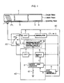
- Fig. 1 is a block diagram of a control signal recording apparatus of the invention.
- T denotes a magnetic tape.
- a video track 11, an audio track 13, and a control track 12 are respectively formed on the tape T as shown in the diagram.
- Video signals, audio signals, and control signals are respectively recorded as well-known formats in those tracks by video heads (rotary heads), audio heads, and control head of a generally well-known video tape recorder.
- a control head 1 is arranged so as to face the control track 12 on the tape T.
- a recording/reproducing switching circuit 20 including a recording/reproducing switch 2 is connected to the control head 1.
- Control signal discriminating means 30 is connected to a reproducing side terminal PB of the switch 2 and comprises an amplifier 3, a demodulator 4, and a cue signal detector 9.
- the amplifier 3 amplifies a control signal P (CTL, Q) reproduced by the control head 1.
- the demodulator 4 is connected to the amplifier 3 and demodulates the duty ratio of the control signal (reproduced pulse) amplified by the amplifier 3.
- the cue signal detector 9 is connected to the domodulator 4 and detects a cue signal Q by discriminating whether the duty ratio of the control signal P demodulated by the demodulator corresponds to the control signal CTL for tracking control or corresponds to the cue signal Q for searching the head of the tape, which will be explained hereinafter.
- An address signal generating means 40 includes a switch 10 to set the recording mode of an address code, a control circuit consisting of an address code generator 8, a duty modulator 6, and an amplifier 7.
- the address code generator 8 is connected to the switch 10, cue signal detector 9 of the control signal discriminating means 30, and demodulator 4.
- the generator 8 When the switch 10 is turned on or when the detector 9 detects the cue signal Q and the generator 8 receives the cue signal Q, the generator 8 outputs a control signal (data "0" and "1") C consisting of a BCD code of, e.g., eight bits and synchronized with an output of the demodulator 4.
- the generator 8 counts an output of the detector 9 and automatically updates an address code, which will be explained hereinafter, thereby preventing the same address code from being generated.
- the modulator 6 is connected to the address code generator 8 and the demodulator 4 of the control signal discriminating means 30 and receives an output signal of generator 8. The modulator 6 then modulates the duty ratio of the reproduced pulse (cue signal Q) of an output signal of the demodulator 4 and generates an address signal A.
- the duty ratio of the cue signal Q differs from the duty ratio of the address signal A as will be explained hereinafter.
- the amplifier 7 is connected to the modulator 6 and a recording side terminal REC of the switch 2 and amplifies an output, i.e., the address signal A of the modulator 6 and then leads the amplified signal to the switch 2.
- Reference numeral 50 denotes recording means for leading the address signal of the address signal generating means 40 to the control head 1 through the switch 2 and thereby recording the address signal A into the control track 12 on the magnetic tape T.
- the recording means 50 includes a recording/reproducing switching control circuit 5, connected to the address code generator 8 and demodulator 4, for receiving the outputs of both generator 8 and demodulator 4 and switching the switch 2 to the recording mode for a predetermined period of time.
- the switch 2 when the switch 2 is connected to the reproducing side PB as shown in the diagram and the apparatus is in the reproducing mode to reproduce the signal (pulse CTL, Q) recorded in the control track 12 on the tape T by the control head 1, the reproduced signal (pulse) P reproduced by the head 1 is supplied to the duty demodulator 4 through the switch 2 and reproducing amplifier 3.
- the demodulator 4 demodulates the duty ratio of the reproduced pulse. Due to the demodulation of the duty ratio of this pulse, it is possible to discriminate whether the reproduced pulse is the control signal CTL to be used for tracking control of the video tape recorder or the cue signal Q to search the head of the tape.
- the cue signal is supplied to the cue signal detector 9 and discriminated and detected by this detector.
- the cue signal Q is supplied to the address code generator 8.
- the generator 8 outputs the control signal (data) C synchronized with the output of the demodulator 4.
- the duty modulator 6 and control circuit 5 are made operative synchronously with the output of the demodulator 4.
- the duty ratio of the reproduced pulse (control signal) is modulated by the modulator 6.
- the modulator 6 then generates the address signal A having a duty ratio different from that of the cue signal Q.
- the control circuit 5 receives the leading edge of the output pulse of the demodulator 4 and outputs a recording/reproducing switching signal D, thereby switching the switch 2 to the recording side terminal REC for a predetermined period of time.
- the address signal A is supplied to the control head 1 through the recording amplifier 7 and the switch 2 and recorded after the cue signal Q in the control track 12 on the tape T by the head 1.
- the recording period of time of the address signal is set by the switching signal D of a proper timing by the control circuit 5 which receives the output of the address code generator 8 and operates.
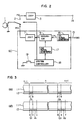
- Fig. 2 is a block diagram of a cue signal recording apparatus.
- Reference numeral 60 denotes cue signal generating means including a mode switch 19, a system controller 18, a cue signal generator 17, a control signal generator 16, the duty modulator 6, and the amplifier 7.
- the system controller 18 switches the switch 2 to the terminal REC for a predetermined period of time and simultaneously makes the cue signal generator 17 operative.
- the system controller 18 switches the switch 2 to the recording side terminal REC and simultaneously makes the cue signal generator 17 operative for a predetermined period of time, thereby allowing an output of the generator 17 to be supplied to the modulator 6.
- the modulator 6 receives the output of the generator 17 and modulates the duty ratio of the control signal CTL of the generator 16 and outputs the cue signal Q.
- the cue signal Q is recorded into the control track 12 on the magnetic tape T through the amplifier 7, switch 2, and head 1.
- Fig. 3(a) is a pattern diagram showing the recording format of the cue signal (Q1, Q2).
- Fig. 3(b) is a pattern diagram showing the recording formats of the cue signal Q (Q1, Q2) and address code A (A1, A2).
- the cue signal Q is recorded in the control track 12 (a to b, d to e) corresponding to the recording start portions of the respective video information (respective scenes n-1, n, n+1, ...) recorded in the video track 11.
- the address signal A is recorded in the control track 12 (b to c, e to f) subsequent to each cue signal Q (a to b, d to e).
- the recording signals having different duty ratios are constituted in the control track 12 in a manner such as "1" signal (the period of a "high” level H occupies 50% or more of the whole period of time) and "0" signal (the period of a "high” level H occupies 20 to 30 % of the whole period of time) as shown in, e.g., Figs. 4(a) and 4(b). Since the leading edge of the control signal CTL is used as a control signal for use in tracking control of the video tape recorder, even if the duty ratio is modulated as mentioned above, no adverse influence will be exerted on the ordinary servo control system.
- the ordinary control signal CTL is recorded at a duty ratio above 50%, so that it is a "1" signal.
- the cue signal Q is recorded automatically or by switching means (switch 10) each time the recording is performed in the ordinary recording mode and is recorded by continuously recording the duty ratio "0" signal a plurality of, e.g., thirty times or the like.
- the address signal A is recorded one by one as an absolute address for each scene in order to make it possible to easily search later the magnetic tape having the recording pattern as shown in Fig. 3(a) which has been recorded in such a manner as mentioned above.
- the modulated signal (pulses) recorded in the control track 12 is reproduced and when the cue signal Q, i.e., the duty ratio "0" signal is continuously detected a predetermined number of times, those reproduced pulses make the modulated signal recording pattern of which, as shown in Fig. 4(b), the first header signal, address signal (e.g., BCD code of eight bits), and second header signal (which is used when the data is reproduced by reversely moving the magnetic tape) have been respectively recorded after the cue signal Q.
- the first header signal, address signal e.g., BCD code of eight bits
- second header signal which is used when the data is reproduced by reversely moving the magnetic tape
- the control circuit 5 receives the output of the demodulator 4, i.e., the leading edge of the control signal having a waveform as shown in Fig. 6(a) and outputs a waveform D as shown in Fig. 6(b), i.e., a recording control signal which becomes a "high (H)" level for only a predetermined period of time of, e.g., 0.15 to 0.85 period.
- the switch 2 is switched to the recording side terminal REC by this control signal, thereby allowing the output of the recording amplifier 7 (i.e., address signal A) as shown in Fig.
- the output of the modulator 6 to be supplied to the recording amplifier 7 becomes a "high (H)" level synchronously with the leading edge of the output (waveform of Fig. 6(a)) of the demodulator 4.
- the period at a "high (H)” level is set to 20 to 30 % when the output C (i.e., address code) is "0", while the period at a "H” level is set to 50 % or more when the address code is "1". (refer to the waveform A of Fig. 6(c)).
- the header signal is set to the signal (e.g., 011110) different from the other signals (address code and the like) and used to determine the timing to detect the address code.
Landscapes
- Indexing, Searching, Synchronizing, And The Amount Of Synchronization Travel Of Record Carriers (AREA)
Applications Claiming Priority (2)
| Application Number | Priority Date | Filing Date | Title |
|---|---|---|---|
| JP60172331A JPH0795390B2 (ja) | 1985-08-07 | 1985-08-07 | 磁気記録再生装置の制御信号記録装置 |
| JP172331/85 | 1985-08-07 |
Publications (3)
| Publication Number | Publication Date |
|---|---|
| EP0211388A2 true EP0211388A2 (fr) | 1987-02-25 |
| EP0211388A3 EP0211388A3 (en) | 1989-03-15 |
| EP0211388B1 EP0211388B1 (fr) | 1992-03-25 |
Family
ID=15939920
Family Applications (1)
| Application Number | Title | Priority Date | Filing Date |
|---|---|---|---|
| EP86110500A Expired - Lifetime EP0211388B1 (fr) | 1985-08-07 | 1986-07-30 | Dispositif d'enregistrement de signaux de commande pour un appareil d'enregistrement/de reproduction magnétique |
Country Status (4)
| Country | Link |
|---|---|
| US (1) | US4707749A (fr) |
| EP (1) | EP0211388B1 (fr) |
| JP (1) | JPH0795390B2 (fr) |
| DE (1) | DE3684528D1 (fr) |
Cited By (6)
| Publication number | Priority date | Publication date | Assignee | Title |
|---|---|---|---|---|
| EP0248945A2 (fr) * | 1986-06-09 | 1987-12-16 | General Service Electronics GmbH | Procédé pour transmettre un code d'information sur la piste de synchronisation d'une bande vidéo, dispositif pour mettre en oeuvre le procédé de même que la bande vidéo fabriquée selon le procédé |
| EP0320743A2 (fr) * | 1987-12-15 | 1989-06-21 | Nokia (Deutschland) GmbH | Magnétoscope avec une bande vidéo comprenant une piste de contrôle additionnelle |
| EP0320744A2 (fr) * | 1987-12-15 | 1989-06-21 | Nokia (Deutschland) GmbH | Magnétoscope avec un dispositif pour enregistrer une piste de contrôle additionnelle sur une bande vidéo |
| DE3932696A1 (de) * | 1988-09-29 | 1990-04-12 | Hitachi Ltd | System fuer einen videobandrekorder zum lesen und aufzeichnen eines sendeprogramms |
| DE3926093C1 (fr) * | 1989-08-08 | 1991-01-24 | Alpermann + Velte Gmbh, 5630 Remscheid, De | |
| EP0602469A2 (fr) * | 1992-12-12 | 1994-06-22 | Deutsche Thomson-Brandt Gmbh | Méthode d'enregistrement sur bande magnétique à pistes obliques |
Families Citing this family (16)
| Publication number | Priority date | Publication date | Assignee | Title |
|---|---|---|---|---|
| JP2555154B2 (ja) * | 1988-06-15 | 1996-11-20 | 株式会社日立製作所 | 頭出し信号自動記録機能付磁気記録再生装置 |
| US5172363A (en) * | 1989-04-13 | 1992-12-15 | Philip Greenspun | Method and apparatus for automatic recording of marker during information recording |
| JPH0317883A (ja) * | 1989-06-15 | 1991-01-25 | Sony Corp | 時間情報発生装置 |
| JPH0770203B2 (ja) * | 1990-01-06 | 1995-07-31 | 日本ビクター株式会社 | デジタルデータ再生装置 |
| KR930005733B1 (ko) * | 1990-12-31 | 1993-06-24 | 삼성전자 주식회사 | 문자로 표시되는 인덱스 서어치 시스템 |
| KR100221067B1 (ko) * | 1991-03-30 | 1999-09-15 | 윤종용 | 비디오 테이프 레코더에서 슬로우 또는 서치시 노이즈 제거 장치 및 방법 |
| ES2107606T3 (es) * | 1992-01-16 | 1997-12-01 | Philips Electronics Nv | Disposicion para registrar una señal de informacion en una pista en un portador de registro. |
| US5341251A (en) * | 1992-02-28 | 1994-08-23 | Ampex Systems Corporation | Data recording system having longitudinal tracks with recordable segments |
| KR0145007B1 (ko) * | 1992-07-31 | 1998-07-15 | 강진구 | 비데오 라이브러리 시스템 및 그 구현방법 |
| JPH06215543A (ja) * | 1992-11-30 | 1994-08-05 | Sony Corp | 記録再生装置 |
| US5987210A (en) * | 1993-01-08 | 1999-11-16 | Srt, Inc. | Method and apparatus for eliminating television commercial messages |
| US5696866A (en) * | 1993-01-08 | 1997-12-09 | Srt, Inc. | Method and apparatus for eliminating television commercial messages |
| US5999688A (en) * | 1993-01-08 | 1999-12-07 | Srt, Inc. | Method and apparatus for controlling a video player to automatically locate a segment of a recorded program |
| US7110658B1 (en) * | 1993-01-08 | 2006-09-19 | Televentions, Llc | Method and apparatus for eliminating television commercial messages |
| JP2937940B2 (ja) * | 1997-04-28 | 1999-08-23 | 日本電気アイシーマイコンシステム株式会社 | 磁気記録再生装置の頭出し信号検出回路 |
| KR102571141B1 (ko) * | 2018-12-07 | 2023-08-25 | 삼성전자주식회사 | 스피커와 마이크를 포함하는 전자 장치 |
Citations (4)
| Publication number | Priority date | Publication date | Assignee | Title |
|---|---|---|---|---|
| FR2045304A5 (fr) * | 1970-04-07 | 1971-02-26 | Braillard Pierre | |
| JPS55108979A (en) * | 1979-02-09 | 1980-08-21 | Mitsubishi Electric Corp | Magnetic recording and reproducing device |
| EP0074841A2 (fr) * | 1981-09-14 | 1983-03-23 | Sony Corporation | Enregistrement et emploi de données de repérages |
| EP0110483A1 (fr) * | 1982-12-07 | 1984-06-13 | Koninklijke Philips Electronics N.V. | Système d'enregistrement et/ou de détection de deux signaux de marquage |
Family Cites Families (9)
| Publication number | Priority date | Publication date | Assignee | Title |
|---|---|---|---|---|
| BE757737A (fr) * | 1969-10-27 | 1971-04-01 | Ampex | Nouveau mode d'enregistrement de l'information |
| US3647951A (en) * | 1970-11-09 | 1972-03-07 | Ampex | Edit control circuit for video tape record system |
| US4007491A (en) * | 1973-08-27 | 1977-02-08 | Lanier Business Products, Inc. | Dictation-transcription method and system |
| IT1085783B (it) * | 1976-05-05 | 1985-05-28 | Cheetham J J | Contenitore |
| JPS55153184A (en) * | 1979-05-15 | 1980-11-28 | Mitsubishi Electric Corp | Signal rewriting unit |
| JPS57195638A (en) * | 1981-05-28 | 1982-12-01 | Shinko Electric Co Ltd | Tire press |
| US4532560A (en) * | 1982-09-16 | 1985-07-30 | Ampex Corporation | Apparatus and method for indicating tape time |
| JPS59139157A (ja) * | 1983-01-26 | 1984-08-09 | Sony Corp | キユ−信号の記録方法 |
| JPS6087487A (ja) * | 1983-10-19 | 1985-05-17 | Matsushita Electric Ind Co Ltd | 磁気記録再生装置の番組検索装置 |
-
1985
- 1985-08-07 JP JP60172331A patent/JPH0795390B2/ja not_active Expired - Fee Related
-
1986
- 1986-07-30 DE DE8686110500T patent/DE3684528D1/de not_active Expired - Lifetime
- 1986-07-30 EP EP86110500A patent/EP0211388B1/fr not_active Expired - Lifetime
- 1986-07-31 US US06/890,924 patent/US4707749A/en not_active Expired - Fee Related
Patent Citations (4)
| Publication number | Priority date | Publication date | Assignee | Title |
|---|---|---|---|---|
| FR2045304A5 (fr) * | 1970-04-07 | 1971-02-26 | Braillard Pierre | |
| JPS55108979A (en) * | 1979-02-09 | 1980-08-21 | Mitsubishi Electric Corp | Magnetic recording and reproducing device |
| EP0074841A2 (fr) * | 1981-09-14 | 1983-03-23 | Sony Corporation | Enregistrement et emploi de données de repérages |
| EP0110483A1 (fr) * | 1982-12-07 | 1984-06-13 | Koninklijke Philips Electronics N.V. | Système d'enregistrement et/ou de détection de deux signaux de marquage |
Non-Patent Citations (3)
| Title |
|---|
| JOURNAL OF THE SMPTE VOL. 76, NO. 3, mARCH 1967, PAGES 169-176; Y. FUJIMURA et al.: "An automatic video-tape editing/splicing system using a process computer" * |
| JOURNAL OF THE SMPTE vol. 76, no. 3, March 1967, pages 169-176; Y. FUJIMURA et al.: "An automatic video-tape editing/splicing system using aprocess computer" page 170, 3rd column, lines 19-31; figures 3a, 3c * |
| PATENT ABSTRACTS OF JAPAN vol. 4, no. 160 (P-35)(642) 8th November 1980; & JP-A-55 108 979 (MITSUBISHI DENKI K.K.) 21-08-1980 * |
Cited By (10)
| Publication number | Priority date | Publication date | Assignee | Title |
|---|---|---|---|---|
| EP0248945A2 (fr) * | 1986-06-09 | 1987-12-16 | General Service Electronics GmbH | Procédé pour transmettre un code d'information sur la piste de synchronisation d'une bande vidéo, dispositif pour mettre en oeuvre le procédé de même que la bande vidéo fabriquée selon le procédé |
| EP0248945A3 (fr) * | 1986-06-09 | 1988-01-13 | General Service Electronics GmbH | Procédé pour transmettre un code d'information sur la piste de synchronisation d'une bande vidéo, dispositif pour mettre en oeuvre le procédé de même que la bande vidéo fabriquée selon le procédé |
| EP0320743A2 (fr) * | 1987-12-15 | 1989-06-21 | Nokia (Deutschland) GmbH | Magnétoscope avec une bande vidéo comprenant une piste de contrôle additionnelle |
| EP0320744A2 (fr) * | 1987-12-15 | 1989-06-21 | Nokia (Deutschland) GmbH | Magnétoscope avec un dispositif pour enregistrer une piste de contrôle additionnelle sur une bande vidéo |
| EP0320743A3 (fr) * | 1987-12-15 | 1991-01-30 | Nokia (Deutschland) GmbH | Magnétoscope avec une bande vidéo comprenant une piste de contrôle additionnelle |
| EP0320744A3 (fr) * | 1987-12-15 | 1991-01-30 | Nokia (Deutschland) GmbH | Magnétoscope avec un dispositif pour enregistrer une piste de contrôle additionnelle sur une bande vidéo |
| DE3932696A1 (de) * | 1988-09-29 | 1990-04-12 | Hitachi Ltd | System fuer einen videobandrekorder zum lesen und aufzeichnen eines sendeprogramms |
| DE3926093C1 (fr) * | 1989-08-08 | 1991-01-24 | Alpermann + Velte Gmbh, 5630 Remscheid, De | |
| EP0602469A2 (fr) * | 1992-12-12 | 1994-06-22 | Deutsche Thomson-Brandt Gmbh | Méthode d'enregistrement sur bande magnétique à pistes obliques |
| EP0602469A3 (fr) * | 1992-12-12 | 1995-11-29 | Thomson Brandt Gmbh | Méthode d'enregistrement sur bande magnétique à pistes obliques. |
Also Published As
| Publication number | Publication date |
|---|---|
| JPH0795390B2 (ja) | 1995-10-11 |
| JPS6233388A (ja) | 1987-02-13 |
| EP0211388A3 (en) | 1989-03-15 |
| EP0211388B1 (fr) | 1992-03-25 |
| DE3684528D1 (de) | 1992-04-30 |
| US4707749A (en) | 1987-11-17 |
Similar Documents
| Publication | Publication Date | Title |
|---|---|---|
| EP0211388B1 (fr) | Dispositif d'enregistrement de signaux de commande pour un appareil d'enregistrement/de reproduction magnétique | |
| EP0223423B1 (fr) | Procédé et appareil d'enregistrement de signaux | |
| EP0969452A1 (fr) | Dispositif de reproduction et d'enregistrement d'informations et circuit de detection de marques de reference | |
| AU583289B2 (en) | Method and apparatus for reproducing signals | |
| GB2115598A (en) | Magnetic recording and/or reproducing apparatus | |
| EP0367440A3 (fr) | Système de suivi automatique de la position de la tête pour des signaux vidéo enregistrés dans un format segmenté | |
| EP0603808A3 (fr) | Un appareil d'enregistrement et de reproduction de signaux numériques. | |
| US5239428A (en) | Magnetic tape recording/reproducing apparatus and method | |
| ATE154740T1 (de) | Aufzeichnungs- und/oder wiedergabegerät mit mitteln zur schaffung eines nachaufzeichnungsbereiches | |
| EP0209151B1 (fr) | Appareil pour enregistrer et/ou reproduire un signal d'information | |
| US5016120A (en) | Apparatus for recording and reproducing a digitized audio signal on a magnetic tape which has a slant track format including means for detecting a control signal to identify a digitized audio signal on the slant track | |
| US4996607A (en) | Audio signal recording apparatus | |
| JPH0580749B2 (fr) | ||
| US5936791A (en) | Helical scan data recording and playback method and apparatus wherein reference helical tracks preceding data recording area on magnetic tape are played back before recording or playback of target data | |
| EP0637823B1 (fr) | Enregistrement/reproduction d'un signal numérique | |
| US5086358A (en) | Recording and reproducing apparatus | |
| JPH0696563A (ja) | 磁気テープの縦方向に再生可能のディジタル情報記録再生装置 | |
| EP0206569A2 (fr) | Appareil d'affichage pour un appareil enregistreur-MIC à multiples canaux | |
| US6188834B1 (en) | Device and method for recording and reproducing image information | |
| US5644446A (en) | Rotary-head digital reproducing/recording method and apparatus with block address-based area signal generation | |
| KR960015998B1 (ko) | 자기기록재생장치 | |
| JP2537769B2 (ja) | 情報信号の編集方法 | |
| JP3211248B2 (ja) | 情報記録装置 | |
| JP3211249B2 (ja) | 情報記録装置 | |
| JPS6223512B2 (fr) |
Legal Events
| Date | Code | Title | Description |
|---|---|---|---|
| PUAI | Public reference made under article 153(3) epc to a published international application that has entered the european phase |
Free format text: ORIGINAL CODE: 0009012 |
|
| 17P | Request for examination filed |
Effective date: 19860730 |
|
| AK | Designated contracting states |
Kind code of ref document: A2 Designated state(s): DE FR GB |
|
| PUAL | Search report despatched |
Free format text: ORIGINAL CODE: 0009013 |
|
| AK | Designated contracting states |
Kind code of ref document: A3 Designated state(s): DE FR GB |
|
| 17Q | First examination report despatched |
Effective date: 19910806 |
|
| GRAA | (expected) grant |
Free format text: ORIGINAL CODE: 0009210 |
|
| AK | Designated contracting states |
Kind code of ref document: B1 Designated state(s): DE FR GB |
|
| REF | Corresponds to: |
Ref document number: 3684528 Country of ref document: DE Date of ref document: 19920430 |
|
| PGFP | Annual fee paid to national office [announced via postgrant information from national office to epo] |
Ref country code: GB Payment date: 19920508 Year of fee payment: 7 |
|
| PGFP | Annual fee paid to national office [announced via postgrant information from national office to epo] |
Ref country code: FR Payment date: 19920529 Year of fee payment: 7 |
|
| ET | Fr: translation filed | ||
| PLBE | No opposition filed within time limit |
Free format text: ORIGINAL CODE: 0009261 |
|
| STAA | Information on the status of an ep patent application or granted ep patent |
Free format text: STATUS: NO OPPOSITION FILED WITHIN TIME LIMIT |
|
| 26N | No opposition filed | ||
| PG25 | Lapsed in a contracting state [announced via postgrant information from national office to epo] |
Ref country code: FR Effective date: 19930331 |
|
| PG25 | Lapsed in a contracting state [announced via postgrant information from national office to epo] |
Ref country code: DE Effective date: 19930401 |
|
| REG | Reference to a national code |
Ref country code: FR Ref legal event code: ST |
|
| PG25 | Lapsed in a contracting state [announced via postgrant information from national office to epo] |
Ref country code: GB Effective date: 19930730 |
|
| GBPC | Gb: european patent ceased through non-payment of renewal fee |
Effective date: 19930730 |