EP0210837A2 - Verfahren zur Anwendung von umgekehrter Osmose - Google Patents
Verfahren zur Anwendung von umgekehrter Osmose Download PDFInfo
- Publication number
- EP0210837A2 EP0210837A2 EP86305659A EP86305659A EP0210837A2 EP 0210837 A2 EP0210837 A2 EP 0210837A2 EP 86305659 A EP86305659 A EP 86305659A EP 86305659 A EP86305659 A EP 86305659A EP 0210837 A2 EP0210837 A2 EP 0210837A2
- Authority
- EP
- European Patent Office
- Prior art keywords
- reverse osmosis
- stage
- solution
- modules
- pressure
- Prior art date
- Legal status (The legal status is an assumption and is not a legal conclusion. Google has not performed a legal analysis and makes no representation as to the accuracy of the status listed.)
- Granted
Links
- 238000001223 reverse osmosis Methods 0.000 title claims abstract description 105
- 238000000034 method Methods 0.000 title claims abstract description 36
- 239000012466 permeate Substances 0.000 claims abstract description 64
- 230000004907 flux Effects 0.000 claims abstract description 59
- 239000012528 membrane Substances 0.000 claims abstract description 41
- 239000005862 Whey Substances 0.000 claims description 31
- 102000007544 Whey Proteins Human genes 0.000 claims description 31
- 108010046377 Whey Proteins Proteins 0.000 claims description 31
- 235000013351 cheese Nutrition 0.000 claims description 18
- 230000003247 decreasing effect Effects 0.000 claims description 12
- 235000013336 milk Nutrition 0.000 claims description 8
- 239000008267 milk Substances 0.000 claims description 8
- 210000004080 milk Anatomy 0.000 claims description 8
- 235000020183 skimmed milk Nutrition 0.000 claims description 5
- 235000010469 Glycine max Nutrition 0.000 claims description 4
- 244000068988 Glycine max Species 0.000 claims description 4
- 235000015203 fruit juice Nutrition 0.000 claims description 4
- 239000000243 solution Substances 0.000 claims 11
- 239000012527 feed solution Substances 0.000 claims 1
- 238000002474 experimental method Methods 0.000 description 49
- 239000007787 solid Substances 0.000 description 22
- 230000007423 decrease Effects 0.000 description 15
- XLYOFNOQVPJJNP-UHFFFAOYSA-N water Substances O XLYOFNOQVPJJNP-UHFFFAOYSA-N 0.000 description 11
- 235000013305 food Nutrition 0.000 description 4
- GUBGYTABKSRVRQ-QKKXKWKRSA-N Lactose Natural products OC[C@H]1O[C@@H](O[C@H]2[C@H](O)[C@@H](O)C(O)O[C@@H]2CO)[C@H](O)[C@@H](O)[C@H]1O GUBGYTABKSRVRQ-QKKXKWKRSA-N 0.000 description 3
- 239000012141 concentrate Substances 0.000 description 3
- 235000013365 dairy product Nutrition 0.000 description 3
- 239000008101 lactose Substances 0.000 description 3
- CURLTUGMZLYLDI-UHFFFAOYSA-N Carbon dioxide Chemical compound O=C=O CURLTUGMZLYLDI-UHFFFAOYSA-N 0.000 description 2
- 238000012423 maintenance Methods 0.000 description 2
- 238000012545 processing Methods 0.000 description 2
- 102000004169 proteins and genes Human genes 0.000 description 2
- 108090000623 proteins and genes Proteins 0.000 description 2
- 238000005406 washing Methods 0.000 description 2
- 101710202015 Protein 1.6 Proteins 0.000 description 1
- 229910002092 carbon dioxide Inorganic materials 0.000 description 1
- 239000001569 carbon dioxide Substances 0.000 description 1
- 238000007796 conventional method Methods 0.000 description 1
- 238000001816 cooling Methods 0.000 description 1
- 238000004090 dissolution Methods 0.000 description 1
- 230000000694 effects Effects 0.000 description 1
- 239000012467 final product Substances 0.000 description 1
- 238000011835 investigation Methods 0.000 description 1
- 238000011017 operating method Methods 0.000 description 1
- 230000003204 osmotic effect Effects 0.000 description 1
- 230000000704 physical effect Effects 0.000 description 1
- 239000000047 product Substances 0.000 description 1
- 230000001105 regulatory effect Effects 0.000 description 1
- 150000003839 salts Chemical class 0.000 description 1
- 239000002904 solvent Substances 0.000 description 1
Images

Classifications
-
- B—PERFORMING OPERATIONS; TRANSPORTING
- B01—PHYSICAL OR CHEMICAL PROCESSES OR APPARATUS IN GENERAL
- B01D—SEPARATION
- B01D61/00—Processes of separation using semi-permeable membranes, e.g. dialysis, osmosis or ultrafiltration; Apparatus, accessories or auxiliary operations specially adapted therefor
- B01D61/02—Reverse osmosis; Hyperfiltration ; Nanofiltration
- B01D61/12—Controlling or regulating
-
- A—HUMAN NECESSITIES
- A23—FOODS OR FOODSTUFFS; TREATMENT THEREOF, NOT COVERED BY OTHER CLASSES
- A23C—DAIRY PRODUCTS, e.g. MILK, BUTTER OR CHEESE; MILK OR CHEESE SUBSTITUTES; MAKING THEREOF
- A23C9/00—Milk preparations; Milk powder or milk powder preparations
- A23C9/14—Milk preparations; Milk powder or milk powder preparations in which the chemical composition of the milk is modified by non-chemical treatment
- A23C9/142—Milk preparations; Milk powder or milk powder preparations in which the chemical composition of the milk is modified by non-chemical treatment by dialysis, reverse osmosis or ultrafiltration
- A23C9/1427—Milk preparations; Milk powder or milk powder preparations in which the chemical composition of the milk is modified by non-chemical treatment by dialysis, reverse osmosis or ultrafiltration by dialysis, reverse osmosis or hyperfiltration, e.g. for concentrating or desalting
-
- B—PERFORMING OPERATIONS; TRANSPORTING
- B01—PHYSICAL OR CHEMICAL PROCESSES OR APPARATUS IN GENERAL
- B01D—SEPARATION
- B01D61/00—Processes of separation using semi-permeable membranes, e.g. dialysis, osmosis or ultrafiltration; Apparatus, accessories or auxiliary operations specially adapted therefor
- B01D61/02—Reverse osmosis; Hyperfiltration ; Nanofiltration
- B01D61/025—Reverse osmosis; Hyperfiltration
- B01D61/026—Reverse osmosis; Hyperfiltration comprising multiple reverse osmosis steps
Definitions
- This invention relates to a reverse osmosis treatment process, particularly a stable reverse osmosis treatment process which is prevented from lowering in throughput capacity by carrying out treatment while keeping the permeate flux of a reverse osmosis membrane constant with the lapse of time.
- reverse osmosis treatment process of this invention is applicable to any solution to be treated so long as the solution is such that the desired end can be attained by applying said process, said process is suitable for the field of food processing.
- Reverse osmosis treatment process comprises applying a pressure higher than osmotic pressure to separate a solvent from solutes through a reverse osmosis membrane, thereby concentrating the solutes.
- a pressure higher than osmotic pressure to separate a solvent from solutes through a reverse osmosis membrane, thereby concentrating the solutes.
- the present inventors have continued investigation on reverse osmosis treatment of dairy products.
- a conventional multistage continuous reverse osmosis apparatus was operated for cheese whey by applying to all modules their repective maximum allowable pressures
- the present inventors experienced the lowering in throughput capacity because of decrease in permeate flux of module in each stage with the lapse of time.
- Such decrease of permeate flux is observed in treatment of the other foods such as milk, skim milk, fruit juices, soybean milk and the ultrafiltrated permeates thereof.
- An object of this invention is to provide a novel reverse osmosis treatment process which can solve these problems.
- a reverse osmosis apparatus (a circulating-loop reverse osmosis apparatus) which comprises a plurality of modules, each of said modules being equipped with a circulating loop connecting a feed port and an exhaust port for a solution to be treated to each other to form a single-stage treating system, said circulating loops of the individual modules being connected in series to form a multistage treating system, and an inlet for feed of solution and an outlet for discharge of solution of said reverse osmosis apparatus formed in the circulating loops of the first stage and the last stage, respectively.
- the average operating pressures in the individual stages are successively increased according as the stage numbers become increased.
- pressure-increasing pumps for increasing the average operating pressures in the individual stages, it is preferable to provide pressure-increasing pumps in and/or between the circulating loops of the individual modules and increase the average operating pressures in the individual stages by operating these pressure-increasing pumps.
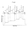
- Fig. 6 (a) shows one example of the above-mentioned circulating-loop reverse osmosis apparatus.
- Numeral 1 shows a module of the first stage
- numeral 2 a module of the second stage
- numeral 3 a module of the third stage
- numeral 4 a feed pump for a solution to be treated
- numeral 5 a pressure control valve
- numeral 21 a circulating loop of the module 1 of the first stage
- numeral 22 a circulating loop of the module 2 of the second stage
- numeral 23 a circulating loop of the module 3 of the third stage
- numeral 11 a circulating pump of the circulating loop 21, numeral 12 a circulating pump of the circulating loop 22, and numeral 13 a circulating pump of the circulating loop 23.
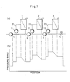
- Fig. 7 (a) shows one example of apparatus constructed by providing pressure-increasing pumps between the circulating loops in the above-mentioned circulating-loop reverse osmosis apparatus.
- Numeral 6 shows a pressure-increasing pump of the circulating loop 22 of the module 2 of the second stage
- numeral 7 a pressure-increasing pump of the circulating loop 23 of the module 3 of the third stage.
- the other numerals in the drawing show corresponding parts in above Fig. 6.
- Fig. 6 (b) is a graph showing the change of pressure and the distribution thereof in the above-mentioned circulating-loop reverse osmosis apparatus of Fig. 6 (a)
- Fig. 7 (b) is a graph showing the change of pressure and the distribution thereof in the circulating-loop reverse osmosis apparatus having pressure-increasing pumps of Fig. 7 (a).
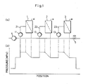
- Fig. 1 (a) is a flow sheet of a conventional three-stage continuous reverse osmosis apparatus.
- Fig. 1 (b) is a graph showing the pressure distribution in the apparatus shown in Fig. 1 (a).
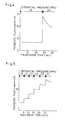
- Fig. 2 is a graph showing the change with the lapse of time of the permeate flux in Experiment 1.
- Fig. 3 is a graph showing the change with the lapse of time of the permeate flux in Experiment 2.
- Fig. 4 is a graph showing the change with the lapse of time of the permeate flux in Experiment 3.
- Fig. 5 is a graph showing the change with the lapse of time of the permeate flux in Experiment 4.
- Fig. 1 (b) is a graph showing the pressure distribution in the apparatus shown in Fig. 1 (a).
- Fig. 2 is a graph showing the change with the lapse of time of the permeate flux in Experiment 1.
- Fig. 3 is a graph showing the change with the lapse of
- FIG. 6 (a) is a flow sheet of one example of reverse osmosis treatment apparatus used in this invention.
- Fig. 6 (b) is a graph showing the pressure distribution in the apparatus shown in Fig. 6 (a).
- Fig. 7 (a) is a flow sheet of another example of reverse osmosis treatment apparatus used in this invention.
- Fig. 7 (b) is a graph showing the pressure distribution in the apparatus shown in Fig. 7 (a).
- numeral 1 shows a module of the first stage, numeral 2 a module of the second stage, numeral 3 a module of the third stage, numeral 11 a circulating pump of the first stage, numeral 12 a circulating pump of the second stage, numeral 13 a circulating pump of the third stage, numeral 21 a circulating loop of the first stage, numeral 22 a circulating loop of the second stage, numeral 23 a circulating loop of the third stage, numeral 4 a feed pump for a solution to be treated, and numeral 5 a pressure control valve.
- the degree of concentration was adjusted by adjusting the feed pump for solution to be treated 4 and the pressure control valve 5 so as to adjust the amount of a product solution (the amount of a concentrate) to about one-third of the amount of the solution to be treated fed by the feed pump for solution to be treated 4.
- Each of the circulating pumps 11, 12 and 13 had a capacity of a circulation rate in module of about 900 liters/hr.
- the pressure loss in module was 0.4 MPa. Since the modules were of intermediate branching type, the net discharge rate was about 1,800 liters/hr which was about twice the circulation rate.
- Fig. 1 (b) show a distribution of pressure in a flow path running through the modules 1, 2 and 3 in Fig. 1 (a), referring to Fig. 1 (a) by means of the alternate long and short dash line. The operating pressures in the modules are shown by the dotted line.
- Fig. 2 shows a change with the lapse of time in the permeate flux of module in the first stage, (b) a change with the lapse of time in the permeate flux of module in the second stage, and (c) a change with the lapse of time in the permeate flux of module in the third stage.
- Reverse osmosis treatment was carried out in the same manner as in Experiment 1, except change of the pH of the cheese whey in experiment 1 to 5.8.
- Reverse osmosis treatment was carried out in the same manner as in Experiment 1, except that as cheese whey as a solution to be treated, there was used cheese whey having a pH of 6.3 and a solids content of 12% (fat 0.1%, protein 1.6%, lactose 9.3%, and ash 1.0%), that the number of modules of a reverse osmosis apparatus was 1 (one-stage treatment), that the treatment temperature was adjusted to about 35°C, and that the average operating pressure was set at 1.8 MPa for about 28 minutes after the beginning of operation, and then at 3.9 PMa for 16 minutes.
- Reverse osmosis treatment was carried out in the same manner as in Experiment 3, except that the change of operating pressure in Experiment 3 was replaced by setting operation pressures at more fixed points than that of Experiment 3 and increasing operating pressure from 1.8 MPa to 3.1 MPa as shown in Fig. 5.
- Reverse osmosis treatment was carried out in the same manner as in Experiment 1, except that in place of the three-stage continuous treatment, there was employed a process which comprises once holding the solution subjected to continuous treatment in the first stage in a tank (not shown in the drawings) outside the system, subjecting the solution to continuous treatment in the second stage, holding the solution in another tank (not shown in the drawings) outside the system, and finally subjecting the solution to continuous treatment in the third stage to obtain a final concentrated solution. There were determined the limiting pressures and the maximum constant permeate fluxes (the maximums of the permeate fluxes which did not decrease with the lapse of time) in the individual stages.
- Reverse osmosis treatment was carried out in the same manner as in Experiment 4, except for use of a reverse osmosis membranes FL-198 and FL-170 (trade names, both mfd. by Teijin Engineering Co., Ltd.), the former having a higher tightness porosity than the reverse osmosis membrane FL-190 used in Experiment 4, and the latter having a lower tightness of porosity than FL-190.
- a reverse osmosis membranes FL-198 and FL-170 trade names, both mfd. by Teijin Engineering Co., Ltd.
- the limiting pressure was 3.23 MPa and the maximum constant permeate flow was 16.4 liters/hr ⁇ m2.
- the limiting pressure was 2.33 MPa and the maximum constant permeate flow was 16.4 liters/hr ⁇ m2.
- Reverse osmosis treatment was carried out in the same manner as in Experiment 5, except that FL-198 being tight membrane was used as a reverse osmosis membrane in the first stage and FL-170 being loose membrane as a reverse osmosis membrane in the third stage, and that the operating pressures in the individual stages were adjusted so as to be close to the operating pressures in the second stage in Experiment 5.
- a reverse osmosis apparatus comprising a plurality of modules, each of said modules being equipped with a circulating loop connecting a feed port and an exhaust port for solution to be treated to each other to form a single-stage treating system, said circulating loops of the individual stages being connected in series to form a multistage treating system, and a for feed of solution inlet and an outlet for discharge of solution of said reverse osmosis apparatus formed in the circulating loops of the first stage and the last stage, respectively, in which the tightness of porosity of reverse osmosis membranes fitted to the individual stages are successively decreased according as the stage numbers become increased, and that the limiting pressures at the individual stages are set so as to be substantially the same by maintaining the average operating pressures in the individual stages so as to be substantially the same, namely, changing the kinds of reverse osmosis
- a reverse osmosis apparatus As a reverse osmosis apparatus in this case, an conventional-type one shown in Fig. 1 (a) can also be used.
- a continuous reverse osmosis apparatus for a single-stage treatment was used in place of the three-stage continuous reverse osmosis apparatus shown in the flow sheet of Fig. 1 (a).
- the module used was Arlamo-26 (a trade name, mfd. by Alpha Laval Co., Ltd.), which was fitted a reverse osmosis membrane FL-190 (a trade name, mfd. buy Teijin Engineering Co., Ltd., PBIL type having a salt rejection percentage of about 90%).
- the effective surface area of each module was 7.92 m2.
- Cheese whey (fat 0.05%, protein 0.8%, lactose 4.65%, ash 0.5%, water 94%, pH 6.4) was used as a solution to be treated, the temperature in the module was adjusted to 10°C, the solution to be treated was fed at a rate of 129 liters/hr by means of a feed pump 4 for solution to be treated, the average circulation rate in the module was adjusted to about 900 liters/hr by means of a circulating pump 11, and operation was conducted while adjusting the average operating pressure to 1.5 MPa by operating a pressure control valve 5.
- Example 2 By use of the same apparatus and solution to be treated as in Example 1, operation was conducted in the same manner as in Example 1, except that the rate of feed by means of the feed pump 4 for solution to be treated was adjusted to 378 liters/hr and that the average operating pressure was adjusted to 2.9 MPa by operating the pressure control valve 5.
- Example 1 There was used a reverse osmosis apparatus comprising three same single-stage apparatuses as used in Example 1 which were arranged in series, and tanks for balance placed between them. The same solution to be treated as in Example 1 was used, and the same module and average circulation rate in module as in Example 1 were also employed, but the operation temperature was adjusted to 40°C.
- the average solids content in module after concentration in the first, second and third stages were predetermined to be about 8.5%, about 12.5% and about 18%, respectively, and experiments in which the average operating pressure was successively increased were previously carried out for wheys having each of these solids concentrations in the same manner as in Experiments 4 to confirm that the limiting pressures in the first, second and third stages were 1.24 MPa, 1.64 MPa and 2.05 MPa, respectively.
- Whey having a solids content of 6% was fed to the reverse osmosis apparatus of the first stage at a rate of 205 liters/hr by means of a feed pump 4 for solution to be treated and circulated through a module by means of a circulating pump, and operation was conducted while adjusting the average operating pressure to 1.24 MPa by operating a control valve at the outlet of the first stage.
- a steady state was reached 30 minutes after the beginning of operation, and whey concentrated to a total solids content of 8.56% could be obtained at a stable capacity of 141 liters/hr for a 2 hours.
- the water permeate flux was maintained at 8.08 liters/hr ⁇ m2.
- the concentrate obtained was once received in a balance tank, and this whey was fed to the next reverse osmosis apparatus of the second stage at a rate of 141 liters/hr in the same manner as with the feed to the first stage and circulated through a module by means of a circulating pump.
- the average operating pressure was adjusted to 1.64 MPa in the same manner as in the first stage.
- a steady state was reached 30 minutes after the beginning of operation, and whey concentrated to a total solids content of 12.75% could be obtained at a stable capacity of 92 liters/hr for 2 hours. During this period of time, the water permeate flux was maintained at 6.19 liters/hr ⁇ m2.
- the concentrate obtained was once received in a balance tank, and this whey was fed to the next reverse osmosis apparatus of the third stage at a rate of 92 liters/hr in the same manner with the feed to the second stage and circulated through a module by means of a circulating pump.
- the average operating pressure was adjusted to 2.04 MPa in the same manner as in the first stage.
- a steady state was reached about 30 minutes after the beginning of operation and whey concentrated to a total solids content of 17.95% could be obtained at a stable capacity of 63 liters/hr for 2 hours.
- the water permeate flux was maintained at 3.66 liters/hr ⁇ m2.
- the three-stage continuous reverse osmosis apparatus shown in Fig. 6 (a) was used. There were used the same modules, reverse osmosis membranes, and solution to be treated as in Example 1, and the average circulation rate in modules was adjusted to 900 liters/hr.
- the average solids contents in modules in the first, second and third stages in the case of 3-fold concentration were predetermined to be about 8.5%, about 12.5% and about 18%, respectively, and the experiments in which the average operating pressure was successively increased were previously carried out for wheys having each of these solids concentrations in the same manner as in Example 4 to confirm that the limiting pressures in the first, second and third stages in the case of operation at 40°C were 1.24 MPa, 1.64 MPa and 2.05 MPa.
- Cheese whey was fed at a temperature of 40°C at a flow rate of 205 liters/hr by means of a feed pump 4 for solution to be treated and circulated through the modules by means of circulating pumps 11, 12 and 13, respectively, and operation was conducted while adjusting the average operating pressures in the first, second and third stages to 1.24 MPa, 1.64 MPa and 2.04 MPa, respectively, by means of a pressure control valve 5 and control valves (not shown in the drawuings) after the respective modules, and adjusting the temperatures in the modules to about 40°C.
- the three-stage continuous reverse osmosis apparatus shown in Fig. 7 (a) was used.
- the modules and the reverse osmosis membranes used were the same as in Example 4, but pressure-increasing pumps 6 and 7 were placed between the circulating loop of the first stage and the circulating loop of the second stage and between the circulating loop of the second stage and the circulating loop of the third stage, respectively.
- Example 2 As a solution to be treated, there was used the same cheese whey as in Example 1, except that its pH was adjusted to pH 5.8 by dissolution of carbon dioxide.
- the cheese whey was intended to be concentrated 3-fold at 40°C, and the average solids contents in the individual modules in the first, second and third stages in this case were predetermined to be 7.7%, 11.6% and 17.4%, respectively.
- Experiments in which the operating pressure was successively increased were previously carried out for wheys having each of these solids concentrations in the same manner as in Example 4 to confirm that the limiting pressures in the first, second and third stages in the case of operation at 40°C were 2.18 MPa, 2.93 MPa and 3.29 MPa, respectively.
- Cheese whey as a solution to be treated was fed at 736 liters/hr by means of a feed pump 4 for solution to be treated and circulated through the modules by means of circulating pumps 11, 12 and 13, respectively. Operation was conducted while adjusting the average operating pressures in the first, second and third stages to 2.16 MPa, 2.91 MPa and 3.27 MPa, respectively, by operating a pressure control valve 5 and control valves (not shown in the drawings) after the respective modules and by operating the pressure-increasing pumps 6 and 7, and while adjusting the temperature to 40°C.
- the three-stage continuous reverse osmosis apparatus shown in Fig. 1 (a) was used.
- the same module as in Example 1 was used, but as reverse osmosis membranes, FL-198, FL-190 and FL-170 (individually trade names, mfd. by Teijin Engineering Co., Ltd.) were used in the first, second and third stages, respectively.
- These reverse osmosis membranes decrease in the tightness of porosity in that order, but each of them had an effective membrane area of 7.92 m2.
- Example 5 The same cheese whey as in Example 5 was used as a solution to be treated, and was intended to be concentrated 3-fold as in Example 5, and the average solids contents in the individual modules in the first, second and third stages in this case were predetermined to be 7.7%, 11.6% and 17.4%, respectively.
- the cheese whey as a solution to be treated was fed at a temperature of 40°C at a flow rate of 720 liters/hr by means of a feed pump 4 for solution to be treated, and circulated through the modules at a circulation rate of about 900 liters/hr by means of circulating pumps 11, 12 and 13, respectively. Operation was conducted while adjusting the average operating pressures of all the modules to 2.9 MPa by operating a pressure control valve 5 and control valves (not shown in the drawings) after the respective modules, and adjusting the temperature to 40°C.
- Fig. 7 (a) The three-stage continuous reverse osmosis apparatus shown in Fig. 7 (a) was used. There was employed a flow mode different from that employed in Example 6, but the module used and the membranes used were the same as in Example 6.
- Example 2 The same cheese whey as in Example 1 was used as a solution to be treated, and was intended to be concentrated 3-fold at 40°C, and the average solids contents in module in the individual stages in this case were predetermined to be 8.5%, 12.5% and 18% in the first, second and third stages, respectively.
- Experiments in which the operating pressure was successively increased were previously carried out for wheys having each of these solids concentrations in the same manner as in Example 4 to confirm that the limiting pressures in the first, second and third stages in the case of operation at 40°C were 1.56 MPa, 1.64 MPa and 1.64 MPa, respectively.
- Cheese whey as a solution to be treated was fed at a temperature of 40°C at a flow rate of 195 liters/hr by means of a feed pump 4 for solution to be treated, and circulated through the modules at a circulation rate of 900 liters/hr by means of circulating pumps 11, 12 and 13, respectively.
- the reverse osmosis treatment process of this invention makes it possible to carry out treatment while keeping the permeate flux of a reverse osmosis membrane constant with the lapse of time, it can keep the throughput capacity constant, can prevent adhesion and pollution onto membrane surfaces and fouling thereon, and moreover can maintain stable operation in continuous run.
Landscapes
- Engineering & Computer Science (AREA)
- Chemical & Material Sciences (AREA)
- Water Supply & Treatment (AREA)
- Nanotechnology (AREA)
- Chemical Kinetics & Catalysis (AREA)
- Life Sciences & Earth Sciences (AREA)
- Food Science & Technology (AREA)
- Polymers & Plastics (AREA)
- Separation Using Semi-Permeable Membranes (AREA)
- Dairy Products (AREA)
Applications Claiming Priority (2)
| Application Number | Priority Date | Filing Date | Title |
|---|---|---|---|
| JP60162816A JPS6227010A (ja) | 1985-07-25 | 1985-07-25 | 逆浸透処理方法 |
| JP162816/85 | 1985-07-25 |
Publications (3)
| Publication Number | Publication Date |
|---|---|
| EP0210837A2 true EP0210837A2 (de) | 1987-02-04 |
| EP0210837A3 EP0210837A3 (en) | 1987-09-30 |
| EP0210837B1 EP0210837B1 (de) | 1993-10-06 |
Family
ID=15761770
Family Applications (1)
| Application Number | Title | Priority Date | Filing Date |
|---|---|---|---|
| EP86305659A Expired - Lifetime EP0210837B1 (de) | 1985-07-25 | 1986-07-23 | Verfahren zur Anwendung von umgekehrter Osmose |
Country Status (4)
| Country | Link |
|---|---|
| EP (1) | EP0210837B1 (de) |
| JP (1) | JPS6227010A (de) |
| DE (1) | DE3689135T2 (de) |
| DK (1) | DK351986A (de) |
Cited By (3)
| Publication number | Priority date | Publication date | Assignee | Title |
|---|---|---|---|---|
| EP0394532A1 (de) * | 1988-03-05 | 1990-10-31 | MEMBRAFLOW GMBH & CO. KG Filtersysteme | Verfahren und Vorrichtung zum Filtrieren von flüssigen Medien |
| WO1998056964A1 (de) * | 1997-06-12 | 1998-12-17 | Frings Recycling-Anlagen Gmbh & Co. Kg | Verfahren zum aufbereiten eines für eine elektrophoretische lackierung eingesetzten elektrolyten |
| CN112566713A (zh) * | 2018-07-20 | 2021-03-26 | 波里费拉公司 | 具有再循环回路的渗透模块 |
Families Citing this family (2)
| Publication number | Priority date | Publication date | Assignee | Title |
|---|---|---|---|---|
| JPH0457294U (de) * | 1990-09-26 | 1992-05-15 | ||
| CN111213712B (zh) * | 2019-10-23 | 2023-09-19 | 内蒙古蒙牛乳业(集团)股份有限公司 | 浓缩方法以及设备 |
Citations (3)
| Publication number | Priority date | Publication date | Assignee | Title |
|---|---|---|---|---|
| US3836457A (en) * | 1973-03-19 | 1974-09-17 | Westinghouse Electric Corp | System for concentrating solutions by low pressure recycling |
| GB2130069A (en) * | 1982-08-06 | 1984-05-31 | Foremost Mckesson | Whey treatment process and product |
| EP0122439A2 (de) * | 1983-03-10 | 1984-10-24 | C.P.C. Engineering Corp. | Verfahren und Vorrichtung zur Erhöhung der Durchflussgeschwindigkeit von Querstromfiltrationsanlagen |
Family Cites Families (3)
| Publication number | Priority date | Publication date | Assignee | Title |
|---|---|---|---|---|
| JPS5328082A (en) * | 1976-08-18 | 1978-03-15 | Ebara Infilco Co Ltd | Membrane separating method |
| JPS5946186A (ja) * | 1982-09-07 | 1984-03-15 | Chlorine Eng Corp Ltd | 高温かん水の逆浸透プロセスによる脱塩方法 |
| JPS5966391A (ja) * | 1982-10-05 | 1984-04-14 | Hibiya Sogo Setsubi Kk | 逆浸透脱塩法 |
-
1985
- 1985-07-25 JP JP60162816A patent/JPS6227010A/ja active Granted
-
1986
- 1986-07-23 DE DE86305659T patent/DE3689135T2/de not_active Expired - Fee Related
- 1986-07-23 EP EP86305659A patent/EP0210837B1/de not_active Expired - Lifetime
- 1986-07-24 DK DK351986A patent/DK351986A/da not_active Application Discontinuation
Patent Citations (3)
| Publication number | Priority date | Publication date | Assignee | Title |
|---|---|---|---|---|
| US3836457A (en) * | 1973-03-19 | 1974-09-17 | Westinghouse Electric Corp | System for concentrating solutions by low pressure recycling |
| GB2130069A (en) * | 1982-08-06 | 1984-05-31 | Foremost Mckesson | Whey treatment process and product |
| EP0122439A2 (de) * | 1983-03-10 | 1984-10-24 | C.P.C. Engineering Corp. | Verfahren und Vorrichtung zur Erhöhung der Durchflussgeschwindigkeit von Querstromfiltrationsanlagen |
Non-Patent Citations (5)
| Title |
|---|
| C.PERI - W.L.DUNKLEY,Journal of Food Science,Vol.36(1991),p.1-25/1-3a "Reverse Osmosis of cottage cheese whey" * |
| J DAIRY SCI. vol. 54, no. 3, 1971, pages 306-311, Champaign, Illinois, US; T.H. LIM et al.: "Role of protein in reverse osmosis of cottage cheese whey" * |
| J DAIRY SCIENCE, vol. 63, no. 2, 1980, pages 204-214, Champaign, Illinois, US; J. HIDDINK et al.: "Reverse osmosis of dairy liquids" * |
| JOURNAL OF DAIRY SCIENCE, vol. 66, no. 12, 1983, pages 2447-2451, Champaign, Illinois, US; D.M. BARBANO et al.: " Influence of reverse osmosis on milk lipolysis" * |
| THE AUSTRALIAN JOURNAL OF DAIRY TECHNOLOGY, vol. 33, no. 2, 1978, pages 57-62, Parkville Victoria, AU; B.R. SMITH et al.: "Fouling in reverse osmosis of whey" * |
Cited By (4)
| Publication number | Priority date | Publication date | Assignee | Title |
|---|---|---|---|---|
| EP0394532A1 (de) * | 1988-03-05 | 1990-10-31 | MEMBRAFLOW GMBH & CO. KG Filtersysteme | Verfahren und Vorrichtung zum Filtrieren von flüssigen Medien |
| WO1998056964A1 (de) * | 1997-06-12 | 1998-12-17 | Frings Recycling-Anlagen Gmbh & Co. Kg | Verfahren zum aufbereiten eines für eine elektrophoretische lackierung eingesetzten elektrolyten |
| CN112566713A (zh) * | 2018-07-20 | 2021-03-26 | 波里费拉公司 | 具有再循环回路的渗透模块 |
| US11878270B2 (en) | 2018-07-20 | 2024-01-23 | Porifera, Inc. | Osmosis modules having recirculation loops |
Also Published As
| Publication number | Publication date |
|---|---|
| JPH0462768B2 (de) | 1992-10-07 |
| EP0210837A3 (en) | 1987-09-30 |
| DK351986D0 (da) | 1986-07-24 |
| DK351986A (da) | 1987-01-26 |
| DE3689135T2 (de) | 1994-05-05 |
| EP0210837B1 (de) | 1993-10-06 |
| DE3689135D1 (de) | 1993-11-11 |
| JPS6227010A (ja) | 1987-02-05 |
Similar Documents
| Publication | Publication Date | Title |
|---|---|---|
| US4876100A (en) | Method for producing milk with a lowered bacterial content | |
| Rektor et al. | Membrane filtration of Mozzarella whey | |
| US5685990A (en) | System and a process for membrane filtration of a dispersion | |
| US3896241A (en) | Preparation of a whey protein concentrate | |
| EP0363896B1 (de) | Bereicherung und Konzentrierung von Proteinen durch Ultrafiltration | |
| US5266202A (en) | Reverse osmosis treatment process | |
| AU2001231543B2 (en) | A process and plant for producing a milk or whey product having a reduced spores and bacteria content | |
| US6051268A (en) | Methods for treating milk products | |
| EP0210837B1 (de) | Verfahren zur Anwendung von umgekehrter Osmose | |
| EP0639054B1 (de) | Verfahren zur herstellung eines hochqualitativen molkeneiweissproduktes | |
| Blais et al. | A review of multistage membrane filtration approaches for enhanced efficiency during concentration and fractionation of milk and whey | |
| US20070158256A1 (en) | Apparatus and method for micro or ultrafiltration | |
| US6291000B1 (en) | Method of concentrating tomato juice by reverse osmosis | |
| US4897277A (en) | Method for producing cheese by means of microfiltration | |
| Trägårdh | Membrane applications in the food industry | |
| Marella et al. | Optimization of spiral-wound microfiltration process for production of micellar casein concentrate | |
| WO2022003161A1 (en) | Control for filtration process | |
| US20230059988A1 (en) | A method for producing a heat-treated concentrated dairy product | |
| CA1094868A (en) | Process for the production of high protein whey products | |
| US5508196A (en) | Method of continuously preparing a sterile culture medium | |
| US11413582B2 (en) | Filtration device | |
| EP3462893B1 (de) | Verfahren zum konzentrieren von rohmilch | |
| Nandini et al. | A review on membrane processes in dairy technology | |
| RU2264717C2 (ru) | Способ производства молочного продукта с пониженным содержанием спор и бактерий и установка для его осуществления, способ получения молочной сыворотки с пониженным содержанием спор и бактерий и установка для его осуществления | |
| EP1307106A2 (de) | Verfaren zur filtration von milch |
Legal Events
| Date | Code | Title | Description |
|---|---|---|---|
| PUAI | Public reference made under article 153(3) epc to a published international application that has entered the european phase |
Free format text: ORIGINAL CODE: 0009012 |
|
| AK | Designated contracting states |
Kind code of ref document: A2 Designated state(s): DE FR GB |
|
| PUAL | Search report despatched |
Free format text: ORIGINAL CODE: 0009013 |
|
| AK | Designated contracting states |
Kind code of ref document: A3 Designated state(s): DE FR GB |
|
| 17P | Request for examination filed |
Effective date: 19871102 |
|
| 17Q | First examination report despatched |
Effective date: 19881018 |
|
| GRAA | (expected) grant |
Free format text: ORIGINAL CODE: 0009210 |
|
| AK | Designated contracting states |
Kind code of ref document: B1 Designated state(s): DE FR GB |
|
| REF | Corresponds to: |
Ref document number: 3689135 Country of ref document: DE Date of ref document: 19931111 |
|
| ET | Fr: translation filed | ||
| PLBE | No opposition filed within time limit |
Free format text: ORIGINAL CODE: 0009261 |
|
| STAA | Information on the status of an ep patent application or granted ep patent |
Free format text: STATUS: NO OPPOSITION FILED WITHIN TIME LIMIT |
|
| 26N | No opposition filed | ||
| REG | Reference to a national code |
Ref country code: GB Ref legal event code: 732E |
|
| REG | Reference to a national code |
Ref country code: FR Ref legal event code: TP |
|
| REG | Reference to a national code |
Ref country code: GB Ref legal event code: IF02 |
|
| PGFP | Annual fee paid to national office [announced via postgrant information from national office to epo] |
Ref country code: GB Payment date: 20040603 Year of fee payment: 19 |
|
| PGFP | Annual fee paid to national office [announced via postgrant information from national office to epo] |
Ref country code: DE Payment date: 20040623 Year of fee payment: 19 |
|
| PGFP | Annual fee paid to national office [announced via postgrant information from national office to epo] |
Ref country code: FR Payment date: 20040715 Year of fee payment: 19 |
|
| PG25 | Lapsed in a contracting state [announced via postgrant information from national office to epo] |
Ref country code: GB Free format text: LAPSE BECAUSE OF NON-PAYMENT OF DUE FEES Effective date: 20050723 |
|
| PG25 | Lapsed in a contracting state [announced via postgrant information from national office to epo] |
Ref country code: DE Free format text: LAPSE BECAUSE OF NON-PAYMENT OF DUE FEES Effective date: 20060201 |
|
| GBPC | Gb: european patent ceased through non-payment of renewal fee |
Effective date: 20050723 |
|
| PG25 | Lapsed in a contracting state [announced via postgrant information from national office to epo] |
Ref country code: FR Free format text: LAPSE BECAUSE OF NON-PAYMENT OF DUE FEES Effective date: 20060331 |
|
| REG | Reference to a national code |
Ref country code: FR Ref legal event code: ST Effective date: 20060331 |