EP0210341A2 - Verfahren und Vorrichtung zum Messen der Kupplungsverluste an Monomode-Lichtwellenleitern - Google Patents
Verfahren und Vorrichtung zum Messen der Kupplungsverluste an Monomode-Lichtwellenleitern Download PDFInfo
- Publication number
- EP0210341A2 EP0210341A2 EP86105221A EP86105221A EP0210341A2 EP 0210341 A2 EP0210341 A2 EP 0210341A2 EP 86105221 A EP86105221 A EP 86105221A EP 86105221 A EP86105221 A EP 86105221A EP 0210341 A2 EP0210341 A2 EP 0210341A2
- Authority
- EP
- European Patent Office
- Prior art keywords
- optical
- face
- fibre
- reflecting
- centre
- Prior art date
- Legal status (The legal status is an assumption and is not a legal conclusion. Google has not performed a legal analysis and makes no representation as to the accuracy of the status listed.)
- Granted
Links
Images

Classifications
-
- G—PHYSICS
- G01—MEASURING; TESTING
- G01M—TESTING STATIC OR DYNAMIC BALANCE OF MACHINES OR STRUCTURES; TESTING OF STRUCTURES OR APPARATUS, NOT OTHERWISE PROVIDED FOR
- G01M11/00—Testing of optical apparatus; Testing structures by optical methods not otherwise provided for
- G01M11/30—Testing of optical devices, constituted by fibre optics or optical waveguides
- G01M11/31—Testing of optical devices, constituted by fibre optics or optical waveguides with a light emitter and a light receiver being disposed at the same side of a fibre or waveguide end-face, e.g. reflectometers
Definitions
- the present invention concerns systems for measuring the characterizing parameters of optical fibres, and more particularly it relates to a method and device for measuring coupling losses in single-mode optical fibres.
- Coupling losses usually occur at joint points between optical fibre trunks and are chiefly due to transverse and/or longitudinal offsets between the two trunks.
- two lengths of the same single-mode optical fibre are placed facing each other with the axes aligned, and an optical beam is injected into them.
- a transverse offset is then introduced between the two fibres which allows the measurement of the optical power transferred from a fibre to the other, and consequently of the amount of the coupling losses.
- the method allows the measurement of the Mode Field Diameter MFD which is a parameter indicative of microbending and coupling losses in single-mode optical fibres.
- Mode Field Diameter is given by twice the transverse offset value for which the measured optical power drops to 1/e times the maximum value.
- the two fibres are held facing each other by means of a high-precision calibrated mechanical device comprising some micromanipulators for the micrometric regulation of fibre alignment and allowing transverse and/or longitudinal offsets of wanted and measurable amounts to be set.
- the two fibres are simply obtained by cutting the same fibre length at a certain point; to obtain the maximum optical power transfer the two end faces ought to be plane, non-corrugated and perpendicular to the fibre axis.
- the present invention of a method of measuring coupling losses between single-mode fibres which in stead of providing the optical power transfer from one fibre length to another facing the first, provides the optical beam reflection in the same fibre length emitting it, by means of a reflecting optical system which in an example of embodiment is a spherical mirror, in another example is a system of collimating lenses followed by a plane mirror, and in a further example is a system of magnifying lenses followed by a spherical mirror.
- the problem is resolved of the mutual rotation of the two end faces, since the image of the section reflected by the reflecting optical systems is orientated with the symmetry axes always parallel to those of the fibre core section.
- the reflected core image moves without rotating with respect to the emitting core, introducing no measurement errors.
- the system, of the present invention allows also the measurement of coupling losses due to the longitudinal offset between two fibre trunks of a joint by simply introducing longitudinal offsets between the fibre and the reflecting optical system.
- the method described in claim 1 is a particular object of the present invention.
- a device and variants for implementing the method, described in claims 2 to 13, are further objects of the present invention.
- the method of measuring coupling losses between single-mode optical fibres resides in the measurement of the optical power reflected by a reflecting optical system in the same optical fibre length guiding the direct beam.
- the core section of the fibre end face opposite to the optical source is placed in the optical centre of the reflecting system to obtain the maximum reflected optical power.
- a relative controlled offset is then introduced between the fibre end face and its image reflected by the reflecting optical system, either in transversal direction, to measure MFD parameter, or in longitudinal direction, to measure separation-dependent losses.
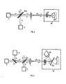
- reference FO is single-mode optical fibre of a given length.
- S denotes a common basically-monochromatic electromagnetic radiation source.
- S can possibly comprise lenses for collimating the optical beam.
- a lens array denoted by L, allows the beam to be focused on fibre FO.
- the technique used to conve y the optical beam into the fibre is usually known and needs no further explanations.
- R denotes a conventional optical detector associated with a system measuring the detected optical power.
- BS1 denotes a common beam splitter inserted along the optical beam path from source S to fibre FO with a determined tilt with respect to the beam.
- SPS indicates a spherical mirror which is the first way of embodiment of the reflecting optical system mentioned while describing the method.
- SPS concavity faces the end face of fibre FO denoted by a : the latter is held, through support SUP, in such a position that the core section of end face a is placed in the curvature centre of spherical mirror SPS.
- the optical centre of the reflecting system is in this case the curvature centre of SPS.
- Dotted line SM indicates the presence of a known type mechanical device containing spherical mirror SPS and support SUP with the end portion of fibre FO comprising face a .
- Mechanical device SM is to allow the micrometric adjustment of the relative positioning of mirror SPS and of end face a , through for instance high-precision calibrated micromanipulators, by which end face a can be positioned in SPS centre, and afterwards a transverse or longitudinal offset of a predetermined measurable value of end face a with respect to centering position can be introduced.
- detector R finds out an optical power reduction, since a more or less considerable portion of optical power is reflected by mirror SPS outside the fibre core section of face a , depending on the value of transverse offset, whereon in turn Mode Field Diameter MFD measurement depends.
- the image of the core of face a reflected by the spherical mirror moves without rotating with respect to the real core.
- the core is not circular, but it has a two-folded symmetry shape, namely an elliptical shape, a significant MFD measurement is obtained, because additional power losses, due to the mutual rotation of the two end-faces found out in the known MFD measurement system, are eliminated.
- Spurious Fresnel reflections occurring at both end faces of the fibre and at lens array L have also to be taken into account: such reflections give rise to a consta nt optical power value, which can be detected by the measuring instrument in the absence of coupling which is to be subtracted from the values measured in the presence of coupling.
- Fig. 2 shows a non-limiting example of modifications to be given to the device of Fig. 1 to facilitate the initial operation of positioning of face a in the curvature centre of mirror SPS.
- MO denotes a usual optical microscope which is inserted into the mechanical device SM in lateral position with respect to the direction of the optical beam which outgoes from the fibre and reaches the mirror.
- BS2 denotes a beam splitter inserted in the trajectory of the optical beam outgoing from face a of the fibre with a tilt such as to form with microscope MO an image of face a itself.
- an optical source is used in the field of the visible e.g. an He-Ne laser denoted by LA which, through a mirror SP, placed between the primary source S and the beam splitter BS1, and lens array L, injects light into fibre FO.
- LA He-Ne laser
- mirror SP interrupts the optical beam emitted by the primary source S which can also remain switched on.
- the positioning in the centre of SPS of the core section of face a is obtained when by microscope MO there can be seen: - the image of face a focused (condition attained by the adjustment in longitudinal direction of the distance between face a and mirror SPS); - the image of the fibre core reflected by SPS coincident with the direct one (condition attained with relative transversal displacements between face a and mirror SPS).
- microscope MO can be left inserted in SM since it does not interfere with the optical-beam direct-path between the fibre and the spherical mirror, while it is sufficient to remove beam splitter BS2: hence from the structural point of view mechanical device SM can provide the fixed position of microscope MO and the housing place of BS2 which can be inserted and removed at will.
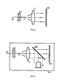
- FIG. 3 shows an alternative embodiment of the reflecting optical system provided by the method.
- the optical system of Fig. 3 consists of a collimating lens array denoted by L1, for example consisting of a reflected-light microscope objective, and of a plane mirror SP1. If the optical beam source is in the focus of L1, the beam rays outgoing therefrom are parallel.
- the optical centre of the lens array corresponds in this example to the focus of lens array L1.
- Fig. 4 shows a non limiting example of how the device of Fig. 3 can be modified to facilitate the initial positioning operation of face a in the focus of the lens array L1.
- the distance between L1 and SP1 (Fig. 4) is not critical and can be adjusted to allow the insertion of beam splitter BS2 along the optical beam path; BS2 is inserted with a tilt, with respect to the optical beam, such as to partly reflect the latter towards a usual telescope OC placed laterally.
- OC function is the same as that of microscope MO of Fig. 2, i.e. that of allowing the positioning of the core section of face a in the focus of system array L1, according to what alre ady described in relation to Fig. 2, with relative displacements between face a of the fibre and lens array L1.
- generators S, LA, detector R, mirrors SP, BS1, lens array L are provided, but not shown for the sake of simplicity, generators S, LA, detector R, mirrors SP, BS1, lens array L as for the example of figures 1 and 2.
- Now mechanical device SM1 of the type of SM of Fig. 2, is to contain fibre FO and its support SUP, lens array L1, mirror SP1, telescope OC and the housing place of beam splitter BS2, which will be inserted only in the initial positioning phase of face a in the focus of L1.
- a transverse offset can be introduced between fibre end face a and reflecting optical system L1-SP1, or plane mirror SP1 can be slightly tilted with respect to the perpendicularity condition, as shown in Fig. 5.
- Reference f denotes the focal distance of lens L1 at which fibre end face a is placed.
- mirror SP1 is tilted by an angle ⁇ with respect to the perpendicularity condition, so that the reflected optical beam has an angle 2 ⁇ with respect to the fibre axis.
- Reference v denotes the longitudinal offset the micromanipulator is to apply to end Q of SP1 to obtain angle ⁇ ; segment practically corresponds to the length of the support of mirror SP1 from hinge point P to point Q, whereto the micromanipulator is coupled.
- a ratio v/x ⁇ 10 can be obtained from typical values of ⁇ 10 cm, f ⁇ 0.5 cm.
- a partly-reflecting spherical mirror can be used as a reflecting optical system in replacement of the totally-reflecting mirror used in the example of embodiment shown in Figures 1, 2. In this way fibre end face a can be observed through the partly-reflecting surface, since a portion of the optical beam traverses the mirror.
- the partly-reflecting spherical mirror used is known in the technique as "Luboshez lens” i.e. a positive aplanatic meniscus lens, described e.g. in the book entitled “Modern Geometrical Optics", by M. Herzberger, issued by Interscience Publishers, Inc., New York, 1958 pages 21, 22, 52; the two mirror surfaces consist of a spherical concave surface and a convex one with a smaller curvature radius.
- a correct virtual image is obtained i.e. with no aberration, but the achromatic one, which, however, in our case does not matter, as monochromatic optical beams are dealt with.
- the virtual image is magnified n2 times the real image, where n is the refractive index of the material the spherical mirror is made of.
- the concave surface of the spherical mirror is metallized to increase its reflectivity.
- the spherical mirror positioning in MFD measurement system is analogous to that of the example of embodiment shown in Fig. 1.
- face a is observed by means of a known lens array placed facing the convex part of the spherical mirror: beam splitter BS2 (Fig. 2) and microscope MO, whose insertion into mechanical device SM is critical owing to the small space available, can thus be eliminated.
- the used spherical mirror can have a wider numerical aperture thus obtaining a better definition of the reflected image, and can form the first lens of the lens array permitting the observation of face a of the fibre.
- the optical system comprises a magnifying lens array L2, consisting of a direct-light microscope objective, and a spherical mirror SPS1 which can be either of the totally or of the partly-reflecting type, previously described.
- the distance between L2 and SPS1 is such that if face a of the fibre is placed at the intersecting point of the working plane with the axis of lens array L2, the latter forms a real magnified image I of face a in the centre of the spherical mirror.
- the magnifying ratio of L2 and the curvature radius of SPS1 must be such that the hypothesis of punctiform image I at the centre of mirror SPS1 may still remain valid.
- lens array L2 allows the use of a spherical mirror SPS1 of reduced numerical aperture.
- the system of fig. 6 is similar to that shown in Fig. 1, but it makes the offset for MFD measurement easier to control.
- spherical mirror SPS1 Holding in fixed position the fibre and lens array L2, spherical mirror SPS1 is transversely displaced; with respect to the transverse offset which ought to be introduced between fibre FO and spherical mirror SPS in the system of Fig. 1, the transverse offset to be given to SPS1 is amplified by a number of times equal to the magnifying ratio of L2 under the same conditions of desired offset between face a and its image reflected by the optical system.
- micromanipulator which regulates the transverse offset of mirror SPS1 is easier to control.
- Said micromanipulator is inserted in the mechanical device (of known type and not shown in the Figure for the sake of simplicity), which comprises support SUP, lens array L2 and mirror SPS1; it is worth noting that the distance on the fibre axis between L2 and SPS1 is fixed and the only possible movement for SPS1 is transverse.
Landscapes
- Physics & Mathematics (AREA)
- Optics & Photonics (AREA)
- Chemical & Material Sciences (AREA)
- Analytical Chemistry (AREA)
- General Physics & Mathematics (AREA)
- Mechanical Coupling Of Light Guides (AREA)
- Optical Couplings Of Light Guides (AREA)
Applications Claiming Priority (2)
| Application Number | Priority Date | Filing Date | Title |
|---|---|---|---|
| IT6766585 | 1985-07-22 | ||
| IT67665/85A IT1199897B (it) | 1985-07-22 | 1985-07-22 | Metodo e dispositivo per la misura delle perdite di accoppiamento tra fibre ottiche monomodo |
Publications (3)
| Publication Number | Publication Date |
|---|---|
| EP0210341A2 true EP0210341A2 (de) | 1987-02-04 |
| EP0210341A3 EP0210341A3 (en) | 1988-05-11 |
| EP0210341B1 EP0210341B1 (de) | 1990-12-05 |
Family
ID=11304334
Family Applications (1)
| Application Number | Title | Priority Date | Filing Date |
|---|---|---|---|
| EP19860105221 Expired EP0210341B1 (de) | 1985-07-22 | 1986-04-16 | Verfahren und Vorrichtung zum Messen der Kupplungsverluste an Monomode-Lichtwellenleitern |
Country Status (6)
| Country | Link |
|---|---|
| US (1) | US4741615A (de) |
| EP (1) | EP0210341B1 (de) |
| JP (1) | JPS6223007A (de) |
| CA (1) | CA1264960A (de) |
| DE (2) | DE210341T1 (de) |
| IT (1) | IT1199897B (de) |
Cited By (1)
| Publication number | Priority date | Publication date | Assignee | Title |
|---|---|---|---|---|
| EP0297669A3 (de) * | 1987-07-02 | 1991-02-06 | Philips Patentverwaltung GmbH | Verfahren zur Messung der von einer Reflexionsstelle reflektierten optischen Strahlung |
Families Citing this family (6)
| Publication number | Priority date | Publication date | Assignee | Title |
|---|---|---|---|---|
| NL9002036A (nl) * | 1990-09-17 | 1992-04-16 | Philips Nv | Inrichting en werkwijze voor het met elektromagnetisch straling aanbrengen van merktekens op een voorwerp, en een voorwerp voorzien van merktekens. |
| US5130535A (en) * | 1990-10-10 | 1992-07-14 | At&T Bell Laboratories | Methods of and apparatus for measuring bending loss along a length of optical fiber |
| US6014486A (en) * | 1997-08-25 | 2000-01-11 | Lucent Technologies, Inc. | Beveled fiber optical tap for use with bulk optic devices |
| US6249626B1 (en) | 1998-03-06 | 2001-06-19 | Lucent Technologies, Inc. | Multimode fiber optical power monitoring tap for optical transmission systems |
| US11808658B2 (en) * | 2019-09-27 | 2023-11-07 | Panduit Corp. | Visual inspector attachment for fiber connector cleaners |
| CN115250144B (zh) * | 2022-06-08 | 2024-04-19 | 华中科技大学 | 多芯光纤可视化耦合与大动态范围串扰测试方法和装置 |
Family Cites Families (12)
| Publication number | Priority date | Publication date | Assignee | Title |
|---|---|---|---|---|
| US3884585A (en) * | 1974-02-25 | 1975-05-20 | Us Navy | Fiber break detection methods for cables using multi-fiber optical bundles |
| DE2620357A1 (de) * | 1976-05-06 | 1977-11-17 | Aeg Telefunken Kabelwerke | Daempfungsmessung in lichtleitern |
| JPS5342846A (en) * | 1976-09-30 | 1978-04-18 | Nippon Telegr & Teleph Corp <Ntt> | Photo coupling device |
| JPS606482B2 (ja) * | 1977-06-03 | 1985-02-19 | 日本電気株式会社 | 光フアイバへの光入射自動調整装置 |
| FR2439397A1 (fr) * | 1978-10-18 | 1980-05-16 | Thomson Csf | Appareil de mesure pour controler des liaisons par fibres optiques |
| JPS5717914A (en) * | 1980-07-08 | 1982-01-29 | Nippon Telegr & Teleph Corp <Ntt> | Aligning method for core axis of optical fiber |
| JPS5782740A (en) * | 1981-08-31 | 1982-05-24 | Nippon Telegr & Teleph Corp <Ntt> | Measuring method for connection loss of optical fiber |
| DD210343A1 (de) * | 1982-03-08 | 1984-06-06 | Inst Fuer Nachrichtentechnik | Verfahren zum messen der uebertragungskapazitaet von lichtleitern |
| US4526467A (en) * | 1982-07-19 | 1985-07-02 | Polaroid Corporation | Apparatus and methods for testing lens structure |
| US4523843A (en) * | 1983-08-04 | 1985-06-18 | Gte Laboratories Incorporated | Optical test set-up for expanded beam connector |
| JPS60107603A (ja) * | 1983-11-17 | 1985-06-13 | Nippon Telegr & Teleph Corp <Ntt> | 偏波保持光フアイバの接続方法 |
| GB2159940A (en) * | 1984-06-01 | 1985-12-11 | Stc Plc | Remote optical sensors |
-
1985
- 1985-07-22 IT IT67665/85A patent/IT1199897B/it active
-
1986
- 1986-04-16 DE DE198686105221T patent/DE210341T1/de active Pending
- 1986-04-16 EP EP19860105221 patent/EP0210341B1/de not_active Expired
- 1986-04-16 DE DE8686105221T patent/DE3675992D1/de not_active Expired - Lifetime
- 1986-04-28 CA CA000507721A patent/CA1264960A/en not_active Expired
- 1986-05-02 JP JP61101240A patent/JPS6223007A/ja active Granted
- 1986-06-03 US US06/870,167 patent/US4741615A/en not_active Expired - Lifetime
Cited By (1)
| Publication number | Priority date | Publication date | Assignee | Title |
|---|---|---|---|---|
| EP0297669A3 (de) * | 1987-07-02 | 1991-02-06 | Philips Patentverwaltung GmbH | Verfahren zur Messung der von einer Reflexionsstelle reflektierten optischen Strahlung |
Also Published As
| Publication number | Publication date |
|---|---|
| JPH052963B2 (de) | 1993-01-13 |
| IT8567665A0 (it) | 1985-07-22 |
| DE3675992D1 (de) | 1991-01-17 |
| IT1199897B (it) | 1989-01-05 |
| JPS6223007A (ja) | 1987-01-31 |
| CA1264960A (en) | 1990-01-30 |
| EP0210341B1 (de) | 1990-12-05 |
| IT8567665A1 (it) | 1987-01-22 |
| EP0210341A3 (en) | 1988-05-11 |
| US4741615A (en) | 1988-05-03 |
| DE210341T1 (de) | 1988-10-13 |
Similar Documents
| Publication | Publication Date | Title |
|---|---|---|
| EP0676629B1 (de) | Brechungsindexmessung von Brillenglas | |
| US5118954A (en) | Method and device for the geometrical characterization of transparent tubes | |
| Gisin et al. | Optical fiber characterization by simultaneous measurement of the transmitted and refracted near field | |
| EP0210341B1 (de) | Verfahren und Vorrichtung zum Messen der Kupplungsverluste an Monomode-Lichtwellenleitern | |
| US4583851A (en) | Method and apparatus for monitoring optical fiber concentricity | |
| Murty et al. | Measurement of long radius of curvature | |
| US4917498A (en) | Arrangement for testing grazing hyperboloids and similar reflective solid bodies for shape deviations | |
| US5265179A (en) | Method of manufacturing fiber-optic collimators | |
| JPH06288735A (ja) | 放物面鏡形状検査測定用の位相共役干渉計 | |
| US20220357430A1 (en) | Fiber-optic Point Probe and Distance Measurement System having a Fiber-optic Point Probe | |
| US3960450A (en) | Lens meter with target orthogonalizer | |
| US3832063A (en) | Lens axis detection using an interferometer | |
| JP3343756B2 (ja) | 光回路用コリメータの製造方法 | |
| NZ200481A (en) | Optical fibre refractive index profile determination | |
| EP0025695B1 (de) | Instrument zum Messen oder Markieren des Abstandes eines Punktes von einer Bezugsfläche oder Linie | |
| Lewis et al. | Interferometer light source and alignment aid using single-mode optical fibres | |
| JPH06129838A (ja) | 傾斜端を有する光ファイバの角度パラメータの測定方法及び該方法の実施に使用する装置 | |
| US4620789A (en) | Endface assessment | |
| JPH0626984A (ja) | ファイバー端面測定装置 | |
| JP3283575B2 (ja) | ファイバー端面測定装置 | |
| EP0532291A1 (de) | Geometrie-Messung der Beschichtungen von optischen Fasern | |
| CA1159645A (en) | Method and apparatus for monitoring optical fiber concentricity | |
| JPH0610643B2 (ja) | レンズの軸の傾き等の測定方法 | |
| RU2022247C1 (ru) | Способ измерения параметров мод планарных оптических волноводов и устройство для его осуществления | |
| SU1254291A1 (ru) | Устройство дл измерени диаметра вала |
Legal Events
| Date | Code | Title | Description |
|---|---|---|---|
| PUAI | Public reference made under article 153(3) epc to a published international application that has entered the european phase |
Free format text: ORIGINAL CODE: 0009012 |
|
| AK | Designated contracting states |
Kind code of ref document: A2 Designated state(s): DE FR GB IT NL SE |
|
| PUAL | Search report despatched |
Free format text: ORIGINAL CODE: 0009013 |
|
| AK | Designated contracting states |
Kind code of ref document: A3 Designated state(s): DE FR GB IT NL SE |
|
| ITCL | It: translation for ep claims filed |
Representative=s name: CSELT TELECOMUNICAZIONI SPA |
|
| EL | Fr: translation of claims filed | ||
| TCNL | Nl: translation of patent claims filed | ||
| DET | De: translation of patent claims | ||
| 17P | Request for examination filed |
Effective date: 19880823 |
|
| 17Q | First examination report despatched |
Effective date: 19900315 |
|
| GRAA | (expected) grant |
Free format text: ORIGINAL CODE: 0009210 |
|
| ITF | It: translation for a ep patent filed | ||
| AK | Designated contracting states |
Kind code of ref document: B1 Designated state(s): DE FR GB IT NL SE |
|
| REF | Corresponds to: |
Ref document number: 3675992 Country of ref document: DE Date of ref document: 19910117 |
|
| RIN2 | Information on inventor provided after grant (corrected) |
Free format text: CALZAVARA, MASSIMO * COPPA, GIANNI * DI VITA, PIETRO |
|
| ET | Fr: translation filed | ||
| ITTA | It: last paid annual fee | ||
| PLBE | No opposition filed within time limit |
Free format text: ORIGINAL CODE: 0009261 |
|
| STAA | Information on the status of an ep patent application or granted ep patent |
Free format text: STATUS: NO OPPOSITION FILED WITHIN TIME LIMIT |
|
| 26N | No opposition filed | ||
| EAL | Se: european patent in force in sweden |
Ref document number: 86105221.5 |
|
| NLS | Nl: assignments of ep-patents |
Owner name: OTC-OPTICAL TECHNOLOGIES CENTER S.R.L. |
|
| REG | Reference to a national code |
Ref country code: GB Ref legal event code: 732E |
|
| REG | Reference to a national code |
Ref country code: FR Ref legal event code: TP |
|
| PGFP | Annual fee paid to national office [announced via postgrant information from national office to epo] |
Ref country code: FR Payment date: 20010330 Year of fee payment: 16 |
|
| PGFP | Annual fee paid to national office [announced via postgrant information from national office to epo] |
Ref country code: SE Payment date: 20010402 Year of fee payment: 16 Ref country code: DE Payment date: 20010402 Year of fee payment: 16 |
|
| PGFP | Annual fee paid to national office [announced via postgrant information from national office to epo] |
Ref country code: GB Payment date: 20010403 Year of fee payment: 16 |
|
| REG | Reference to a national code |
Ref country code: GB Ref legal event code: 732E |
|
| PGFP | Annual fee paid to national office [announced via postgrant information from national office to epo] |
Ref country code: NL Payment date: 20010412 Year of fee payment: 16 |
|
| REG | Reference to a national code |
Ref country code: GB Ref legal event code: IF02 |
|
| PG25 | Lapsed in a contracting state [announced via postgrant information from national office to epo] |
Ref country code: GB Free format text: LAPSE BECAUSE OF NON-PAYMENT OF DUE FEES Effective date: 20020416 |
|
| PG25 | Lapsed in a contracting state [announced via postgrant information from national office to epo] |
Ref country code: SE Free format text: LAPSE BECAUSE OF NON-PAYMENT OF DUE FEES Effective date: 20020417 |
|
| PG25 | Lapsed in a contracting state [announced via postgrant information from national office to epo] |
Ref country code: NL Free format text: LAPSE BECAUSE OF NON-PAYMENT OF DUE FEES Effective date: 20021101 Ref country code: DE Free format text: LAPSE BECAUSE OF NON-PAYMENT OF DUE FEES Effective date: 20021101 |
|
| EUG | Se: european patent has lapsed |
Ref document number: 86105221.5 |
|
| GBPC | Gb: european patent ceased through non-payment of renewal fee |
Effective date: 20020416 |
|
| PG25 | Lapsed in a contracting state [announced via postgrant information from national office to epo] |
Ref country code: FR Free format text: LAPSE BECAUSE OF NON-PAYMENT OF DUE FEES Effective date: 20021231 |
|
| NLV4 | Nl: lapsed or anulled due to non-payment of the annual fee |
Effective date: 20021101 |
|
| REG | Reference to a national code |
Ref country code: FR Ref legal event code: ST |
|
| PG25 | Lapsed in a contracting state [announced via postgrant information from national office to epo] |
Ref country code: IT Free format text: LAPSE BECAUSE OF NON-PAYMENT OF DUE FEES;WARNING: LAPSES OF ITALIAN PATENTS WITH EFFECTIVE DATE BEFORE 2007 MAY HAVE OCCURRED AT ANY TIME BEFORE 2007. THE CORRECT EFFECTIVE DATE MAY BE DIFFERENT FROM THE ONE RECORDED. Effective date: 20050416 |