EP0210133A2 - Device for minutely dosing a liquid-film on a roller of a printing press - Google Patents
Device for minutely dosing a liquid-film on a roller of a printing press Download PDFInfo
- Publication number
- EP0210133A2 EP0210133A2 EP86810319A EP86810319A EP0210133A2 EP 0210133 A2 EP0210133 A2 EP 0210133A2 EP 86810319 A EP86810319 A EP 86810319A EP 86810319 A EP86810319 A EP 86810319A EP 0210133 A2 EP0210133 A2 EP 0210133A2
- Authority
- EP
- European Patent Office
- Prior art keywords
- roller
- belt
- liquid
- rotating roller
- film
- Prior art date
- Legal status (The legal status is an assumption and is not a legal conclusion. Google has not performed a legal analysis and makes no representation as to the accuracy of the status listed.)
- Granted
Links
Images

Classifications
-
- B—PERFORMING OPERATIONS; TRANSPORTING
- B41—PRINTING; LINING MACHINES; TYPEWRITERS; STAMPS
- B41F—PRINTING MACHINES OR PRESSES
- B41F31/00—Inking arrangements or devices
- B41F31/20—Ink-removing or collecting devices
Definitions
- the invention relates to a device for fine metering and balancing a liquid film created by a liquid application device on a rotating roller of a printing press with a liquid-permeable fine metering belt which loops around the rotating roller and strips off the excess ink, which in turn runs into a catch basin, the liquid application device being used every revolution of the rotating roller completely renews the liquid film.
- Such a device is shown in DE-OS 2146045, in which a gauze is stretched against the ductor roller by a roller inking unit of an office offset printing machine for metering the amount of ink on the duct roller.
- the duct roller has a substantially lower peripheral speed than the cylinder on which the printing form is arranged. For this reason, it is necessary to arrange a lifting roller after the duct roller.
- This siphon roller takes on the ink at the same peripheral speed as the duct roller rotates and transfers it to a 1st inking roller which has the same peripheral speed as the printing form cylinder.
- DE-OS 28 12 998 shows a roller that directly colors the printing plate of the plate cylinder. This roller is forced to have a soft, rubber-elastic surface. The ink applied to the roller by an ink fountain is stripped off by an ink knife in such a way that the ink film has the thickness necessary for further processing.
- the inking roller with the rubber-elastic surface according to DE-OS 28 12 998 is preceded by an ink cylinder provided with a rigid surface, on which an ink film by means of metering elements is generated to avoid the strong elastic deformation of the soft surface of the roller.
- This additional inking roller which makes the whole arrangement more expensive, must have the exact same diameter as the plate cylinder, so that the appearance of so-called ghost images is prevented.
- An additional inking roller between the plate cylinder and the ink cylinder must be arranged to avoid two rollers with a hard surface coming into contact with each other.
- the ink film that is created on the inking roller is not completely balanced and renewed.
- the residual ink film not picked up by the plate cylinder and remaining on the inking roller is overlaid with new ink the next time it is touched with the ink cylinder, which is repeated with each new rotation. For this reason, dirt and unclean pressure can occur.
- This contamination can lead to the metering gap also becoming dirty, which leads to uneven ink supply and increased wear.
- With the contact line between the support body and the ink cylinder these dirt particles can also lead to increased wear.
- the risk of a backlog of color, which originates from the residual film that remains on the ink cylinder is very high and must somehow be derived.
- the object of the invention is to provide a device which makes it possible to produce a finely metered liquid film on a rotating roller with the least possible number of rollers, which film is created and compensated for every revolution of the rotating roller, and which further mentioned Avoids disadvantages.
- the object is achieved in that the rotating roller comes into contact with an axially parallel forme cylinder carrying a printing form, and thereby transfers the stripping belt, which is wrapped around the rotating roller, to the required amount of liquid film, which is necessary for further processing, on the printing form, the rotating roller having a circumferential speed which corresponds practically to that of the forme cylinder.
- the surface quality and the surface hardness of the rotating roller can be adapted in virtually any manner to the printing process, to the liquid to be processed or to the processing speed.
- the dosing screws and their expensive control device are omitted for fine dosing of the liquid film on the rotating roller.
- the quality of the belt can be varied practically as desired and adapted to the requirements of the work process, since between the scraper belt and the rotating roller, due to the hydrodynamic pressure at production speed, there is pure fluid friction and the wear is therefore very low.
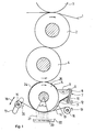
- Fig. 1 shows schematically a printing unit of a printing press, in which a paper web 1, which is printed, is passed in a known manner between a rubber cylinder 2 and an impression cylinder 3, which are rotatably mounted in a machine frame, not shown.
- a plate cylinder 4 is assigned to the blanket cylinder 2, from which the print image is transferred to the blanket cylinder 2.
- the plate cylinder 4 receives ink and / or dampening solution from a rotating roller 5.
- the rotating roller 5, like the blanket cylinder 2 and plate cylinder 4, is driven by a known device (not shown), the peripheral speeds being the same.
- the rotating roller 5 receives the liquid 6 from a liquid application device 7.
- This liquid application device 7 is limited, for example, on the one hand by a rear wall 8, side walls 9, metering knife 10 and, on the other hand, by the rotating roller 5.
- a gap 11 between metering knife 10 and rotating roller 5, its Width is set once by adjusting screws 12 at the start of operation, determines the film thickness 13 of the liquid which the rotating roller 5 takes with it.
- the tension of the scraper belt 14 can be varied with the brakeable unwinding shaft 15. Braked unwinding shaft 15 and drivable winding shaft 16 make it possible to replace, for example, a worn area of the stripping belt 14 by wrapping in the direction of the arrows 19 and 20 in the simplest way by a new area of the stripping belt 14, which can easily be done during operation of the printing press.
- the stripping belt 14 strips off the liquid adhering to the rotating roller 5, the stripped liquid 21 being guided away through the spaces and running into a collecting basin 22. From there, the liquid 23 passes through lines (not shown) into a known processing device. The remaining liquid film 24 is then the Plate cylinder 4 supplied. The then remaining liquid residue 25 is completely renewed in the liquid container 7.
- the blanket cylinder 2 can be replaced by an impression cylinder and the plate cylinder 4 by a plate or form cylinder corresponding to the type of printing, the web to be printed passing between these cylinders.
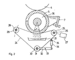
- 2 shows an embodiment of a device for the fine metering of a liquid film on a rotating roller 5, the stripping belt 14 being designed as an endless belt 24. This endless belt 24 is guided over rollers.
- the drivable roller 25 is firmly seated on a rotatable, stationary shaft 26 which is driven by a continuously variable motor 27.
- the pivotable roller 28 in turn sits on a shaft 29, the position of which can be changed to adjust the wrap angle ⁇ .
- a tensionable roller 30 is freely rotatable on an axis 31.
- the axis 31 is stuck in one end of a lever 32 which can be rotated about a fixed axis 33.
- the other end of the lever 32 is connected in an articulated manner to a pressure cylinder 34 which is rotatably articulated on a fixed pin 35.
- this pressure cylinder 34 With the help of this pressure cylinder 34, the required tension of the endless belt 24 is achieved by adjusting the pressurizing pressure of the medium.
- the rotating roller 5 is provided with a cavity 36, which enables cooling of the rotating roller 5 which may be necessary.
- the device shown in FIG. 3 is also provided with an endless belt 24, like the embodiment shown in FIG. 2.
- the endless belt 24 runs over a drivable roller 37, a pivotable roller 38 and a tensionable roller 39.
- the drivable roller 37 is driven by a continuously variable motor 27.
- Another roller 41 which is arranged on a stationary shaft 42, lies in the region of a cleaning basin 43 which is filled with a cleaning agent 44. When not in use, the cleaning basin 43 can be lowered into a lower layer 45 (shown in dashed lines).
- the belt outlet runs through a device 46 or 47, which removes unnecessary cleaning agent from the endless belt 24, for example by wiping it off.
- the device 46 or 47 is in engagement, depending on the running direction of the endless belt 24. This arrangement also makes it possible to clean the rotating roller 5.
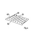
- the base material consists of a film 48, which can be, for example, metallic or plastic, the side of which facing the rotating roller 5 has a smooth surface, and which is provided with a number of rows of holes 49.
- the oval holes 50 for example, allow the liquid stripped by the webs 51 remaining between them to run away and to flow into the collecting basin 22.
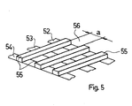
- FIG. 5 shows a further embodiment of the stripping belt used for the device described.
- Webs 55 are arranged on inextensible but flexible band strips 52, 53, 54, which are at a mutual distance a.
- the space 56 formed in this way allows that the liquid stripped off by the webs 55 can run away and reaches the catch basin 22 (FIG. 1).
- All the adjustment devices of this invention can of course be automated, for example the various setting variables are stored in a control unit and the various programs can thus be run.
- the entire scraper belt holder and / or liquid container can be accommodated in boxes which have lateral boundaries and can therefore be easily replaced.
- the width of the boxes can be such that several boxes can be arranged across the roll width.
Abstract
Description
Die Erfindung bezieht sich auf eine Vorrichtung zum Feindosieren und Ausgleichen eines auf einer rotierenden Walze einer Druckmaschine von einer Flüssigkeitsauftragsvorrichtung geschaffenen Flüssigkeitsfilms mit einem flüssigkeitsdurchlässigen Feindosierband, welches die rotierende Walze umschlingt und die überschüssige Farbe abstreift, die ihrerseits in ein Auffangbecken läuft, wobei die Flüssigkeitsauftragsvorrichtung bei jeder Umdrehung der rotierenden Walze den Flüssigkeitsfilm vollständig erneuert.The invention relates to a device for fine metering and balancing a liquid film created by a liquid application device on a rotating roller of a printing press with a liquid-permeable fine metering belt which loops around the rotating roller and strips off the excess ink, which in turn runs into a catch basin, the liquid application device being used every revolution of the rotating roller completely renews the liquid film.
Eine derartige Vorrichtung zeigt die DE-OS 2146045, in welcher zum Dosieren der Farbmenge auf der Duktorwalze von einem Walzenfarbwerk einer Büro-Offsetdruckmaschine gegen die Duktorwalze eine Gaze gespannt ist. Die Duktorwalze weist eine wesentlich kleinere Umfangsgeschwindigkeit auf, als der Zylinder, auf welchem die Druckform angeordnet ist. Aus diesem Grunde ist es notwendig, der Duktorwalze eine Heberwalze nachzuordnen. Diese Heberwalze übernimmt die Farbe mit derselben Umfangsgeschwindigkeit, wie die Duktorwalze dreht und überträgt sie auf eine 1. Farbwalze, welche dieselbe Umfangsgeschwindigkeit aufweist wie der Druckformzylinder. Durch diese Pendelbewegung der Heberwalze, bei welcher abwechselnd Farbe von der Duktorwalze aufgenommen und an die 1. Farbwalze abgegeben wird, entsteht naturgemäss auf der 1. Farbwalze kein einheitlicher Farbfilm wie er zur Einfärbung der Druckform erforderlich ist. Darum ist es zwingend notwendig, zwischen der 1. Farbwalze und dem Druckformzylinder eine Anzahl weiterer Farbwalzen anzuordnen, welche dafür besorgt sind, die nicht konstant zugeführte Farbe bis zur Druckform derart auszugleichen, dass ein gleichmässiger Farbfilm auf die Druckform übertragen werden kann.Such a device is shown in DE-OS 2146045, in which a gauze is stretched against the ductor roller by a roller inking unit of an office offset printing machine for metering the amount of ink on the duct roller. The duct roller has a substantially lower peripheral speed than the cylinder on which the printing form is arranged. For this reason, it is necessary to arrange a lifting roller after the duct roller. This siphon roller takes on the ink at the same peripheral speed as the duct roller rotates and transfers it to a 1st inking roller which has the same peripheral speed as the printing form cylinder. This pendulum movement of the lifter roller, in which ink is alternately taken up by the duct roller and delivered to the 1st inking roller, naturally there is no uniform ink film on the first inking roller as is required to color the printing form. It is therefore imperative to arrange a number of additional inking rollers between the 1st inking roller and the printing form cylinder, which are responsible for compensating the non-constantly supplied ink up to the printing form in such a way that a uniform ink film can be transferred to the printing form.
Des weiteren sind Vorrichtungen bekannt, mit welchen ein Dosieren einer Flüssigkeit auf einer Walze erreicht werden kann, dass ein brauchbarer Flüssigkeitsfilm entsteht, ohne dass eine Reihe von Reiberwalzen notwendig sind. Die DE-OS 28 12 998 zeigt eine Walze, die direkt die Druckplatte des Plattenzylinders einfärbt. Diese Walze ist gezwungenermassen mit einer weichen, gummielastischen Oberfläche versehen. Die von einem Farbkasten auf die Walze aufgetragenen Farbe wird von einem Farbmesser abgestreift, und zwar so, dass der Farbfilm die für die Weiterverarbeitung notwendige Dicke aufweist. Dies bedeutet aber, da sich die Dicke des Farbfilms in der Grössenordnung von einigen Tausendstels Millimeter bewegt, dass das Farbmesser zur Ueberwindung des hydrodynamischen Druckes, mit sehr grosser Kraft gegen die Walze gepresst wird, und dadurch die Oberfläche der Walze stark elastisch verformt wird. Diese Verformung verursacht aber unweigerlich eine starke Erwärmung und einen grossen Verschleiss, in starkem Masse von der Geschwindigkeit abhängig.Furthermore, devices are known with which a metering of a liquid on a roller can be achieved so that a usable liquid film is formed without the need for a series of friction rollers. DE-OS 28 12 998 shows a roller that directly colors the printing plate of the plate cylinder. This roller is forced to have a soft, rubber-elastic surface. The ink applied to the roller by an ink fountain is stripped off by an ink knife in such a way that the ink film has the thickness necessary for further processing. However, this means that since the thickness of the ink film is of the order of a few thousandths of a millimeter, the ink knife is pressed against the roller with very great force in order to overcome the hydrodynamic pressure, and the surface of the roller is thereby deformed in a highly elastic manner. However, this deformation inevitably causes severe heating and wear, to a large extent depending on the speed.
In der DE-OS 32 17 569 wird der Farbauftragswalze mit der gummielastischen Oberfläche nach der DE-OS 28 12 998 ein mit einer starren Oberfläche versehener Farbzylinder vorgelagert, auf welchem ein Farbfilm mittels Dosierelementen erzeugt wird, um die starke elastische Verformung der weichen Oberfläche der Walze zu vermeiden.In DE-OS 32 17 569, the inking roller with the rubber-elastic surface according to DE-OS 28 12 998 is preceded by an ink cylinder provided with a rigid surface, on which an ink film by means of metering elements is generated to avoid the strong elastic deformation of the soft surface of the roller.
Diese zusätzliche, die ganze Anordnung verteuernde Farbauftragswalze muss den genau gleichen Durchmesser aufweisen, wie der Plattenzylinder, damit das Erscheinen von sogenannten Geisterbildern verhindert wird. Eine zusätzliche Farbauftragswalze zwischen Plattenzylinder und Farbzylinder muss aber angeordnet werden, um zu vermeiden, dass zwei Walzen mit harter Oberfläche miteinander in Berührung kommen.This additional inking roller, which makes the whole arrangement more expensive, must have the exact same diameter as the plate cylinder, so that the appearance of so-called ghost images is prevented. An additional inking roller between the plate cylinder and the ink cylinder must be arranged to avoid two rollers with a hard surface coming into contact with each other.
Der Farbfilm, welcher auf der Farbauftragswalze erzeugt wird, wird nicht vollständig ausgeglichen und erneuert. Der vom Plattenzylinder nicht aufgenommene, auf der Farbauftragswalze verbleibende Restfarbfilm wird bei der nächsten Berührung mit dem Farbzylinder mit neuer Farbe überlagert, was sich bei jeder neuerlichen Umdrehung wiederholt. Aus diesem Grund kann es zu Verschmutzungen und unsauberem Druck kommen. Diese Verschmutzungen können dazu führen, dass auch der Dosierspalt verschmutzt wird, was zu ungleichmässiger Farbzuführung und erhöhter Abnützung führt. Bei der Berührungslinie Stützkörper-Farbzylinder können diese Schmutzpartikel ebenfalls zu erhöhter Abnützung führen. Gleichzeitig ist hier die Gefahr eines Rückstaus von Farbe, welche vom Restfilm herrührt, der auf dem Farbzylinder bleibt, sehr gross und muss irgendwie abgeleitet werden.The ink film that is created on the inking roller is not completely balanced and renewed. The residual ink film not picked up by the plate cylinder and remaining on the inking roller is overlaid with new ink the next time it is touched with the ink cylinder, which is repeated with each new rotation. For this reason, dirt and unclean pressure can occur. This contamination can lead to the metering gap also becoming dirty, which leads to uneven ink supply and increased wear. With the contact line between the support body and the ink cylinder, these dirt particles can also lead to increased wear. At the same time, the risk of a backlog of color, which originates from the residual film that remains on the ink cylinder, is very high and must somehow be derived.
Die Anforderungen an die Genauigkeit von Dosierelement und Farbzylinder sind sehr hoch, was sich wiederum in einer Verteuerung dieses Farbwerks niederschlägt.The requirements for the accuracy of the dosing element and ink cylinder are very high, which in turn results in an increase in the price of this inking unit.
Die Aufgabe der Erfindung besteht darin, eine Vorrichtung zu schaffen, welche ermöglicht, mit der geringstmöglichen Anzahl von Walzen einen feindosierten Flüssigkeitsfilm auf einer rotierenden Walze zu erzeugen, welcher bei jeder Umdrehung der rotierenden Walze vollständig neu geschaffen und ausgeglichen wird, und die die weiteren erwähnten Nachteile vermeidet.The object of the invention is to provide a device which makes it possible to produce a finely metered liquid film on a rotating roller with the least possible number of rollers, which film is created and compensated for every revolution of the rotating roller, and which further mentioned Avoids disadvantages.
Erfindungsgemäss erfolgt die Lösung der Aufgabe dadurch, dass die rotierende Walze mit einem achsparallelen, eine Druckform tragenden Formzylinder in Anlage kommt, und dabei den durch mindestens ein das die rotierende Walze umschlingende Abstreifband auf das für die Weiterverarbeitung notwendige Mass feindosierten Flüssigkeitsfilm auf die Druckform überträgt, wobei die rotierende Walze eine praktisch der des Formzylinders entsprechende Umfangsgeschwindigkeit aufweist.According to the invention, the object is achieved in that the rotating roller comes into contact with an axially parallel forme cylinder carrying a printing form, and thereby transfers the stripping belt, which is wrapped around the rotating roller, to the required amount of liquid film, which is necessary for further processing, on the printing form, the rotating roller having a circumferential speed which corresponds practically to that of the forme cylinder.
Bei einer solchen Vorrichtung kann die Oberflächenbeschaffenheit und die Oberflächenhärte der rotierende Walze in praktisch beliebiger Art an das Druckverfahren, an die zu verarbeitende Flüssigkeit oder an die Verarbeitungsgeschwindigkeit angepasst werden. Die Dosierschrauben und deren teure Steuereinrichtung fallen zum Feindosieren des Flüssigkeitsfilms auf der rotierenden Walze weg. Die Beschaffenheit des Bandes kann praktisch beliebig variiert und an die Anforderungen des Arbeitsprozesses angepasst werden, da zwischen Abstreifband und rotierender Walze infolge des hydrodynamischen Druckes bei Produktionsgeschwindigkeit eine reine Flüssigkeitsreibung entsteht und somit auch der Verschleiss sehr gering ist.With such a device, the surface quality and the surface hardness of the rotating roller can be adapted in virtually any manner to the printing process, to the liquid to be processed or to the processing speed. The dosing screws and their expensive control device are omitted for fine dosing of the liquid film on the rotating roller. The quality of the belt can be varied practically as desired and adapted to the requirements of the work process, since between the scraper belt and the rotating roller, due to the hydrodynamic pressure at production speed, there is pure fluid friction and the wear is therefore very low.
In der Zeichnung sind Ausführungsbeispiele der erfindungsgemässen Vorrichtung dargestellt, die nachfolgend näher er läutert werden.In the drawing, exemplary embodiments of the device according to the invention are shown, which he explains in more detail below to be refined.
Es zeigt:
- Fig. 1 eine vereinfachte Seitenansicht eines Druckwerkes mit einer Vorrichtung zur Schaffung eines feindosierten Flüssigkeitsfilms in Form eines auf Rollen gewickelten Abstreifbandes,
- Fig. 2 eine Seitenansicht der Walze und einem Endlosband,
- Fig. 3 eine Seitenansicht der Walze und dem Endlosband, welches eine Reinigungsvorrichtung durchläuft,
- Fig. 4 eine Ausführungsmöglichkeit des Abstreifbandes,
- Fig. 5 eine weitere Ausführungsmöglichkeit des Abstreifbandes.
- 1 is a simplified side view of a printing unit with a device for creating a finely metered liquid film in the form of a stripping tape wound on rolls,
- 2 is a side view of the roller and an endless belt,
- 3 is a side view of the roller and the endless belt which passes through a cleaning device,
- 4 shows an embodiment of the scraper belt,
- Fig. 5 shows a further embodiment of the scraper.
Fig. 1 zeigt schematisch ein Druckwerk einer Druckmaschine, bei der in bekannter Weise eine Papierbahn 1, welche bedruckt wird, zwischen einem Gummizylinder 2 und einem Gegendruckzylinder 3, welche in einem nicht dargestellten Maschinenrahmen drehbar gelagert sind, hindurchgeführt wird. Dem Gummizylinder 2 ist ein Plattenzylinder 4 zugeordnet, von welchem das Druckbild auf den Gummizylinder 2 übertragen wird. Der Plattenzylinder 4 erhält Farbe und/oder Feuchtmittel von einer rotierenden Walze 5. Die rotierende Walze 5 wird, wie Gummizylinder 2 und Plattenzylinder 4, durch eine nicht dargestellte, bekannte Vorrichtung angetrieben, wobei die Umfangsgeschwindigkeiten gleich sind.Fig. 1 shows schematically a printing unit of a printing press, in which a paper web 1, which is printed, is passed in a known manner between a
Die rotierende Walze 5 erhält die Flüssigkeit 6 von einer Flüssigkeitsauftragsvorrichtung 7. Diese Flüssigkeitsauftragsvorrichtung 7 wird beispielsweise einerseits begrenzt durch eine Rückwand 8, Seitenwände 9, Dosiermesser 10 und andererseits durch die rotierende Walze 5. Ein Spalt 11 zwischen Dosiermesser 10 und rotierender Walze 5, dessen Weite durch Stellschrauben 12 bei Betriebsbeginn einmalig eingestellt wird, bestimmt die Filmdicke 13 der Flüssigkeit, welche die rotierende Walze 5 mitnimmt. Ein Abstreifband 14, dessen Beschaffenheit beispielsweise aus einem kunststoffenen und/oder metallenem Gewebe besteht, ist an seinen beidseitigen Enden aufgewickelt.The rotating
Während das eine Ende auf einer bremsbaren Abwickelwelle 15 aufgewickelt ist, die ortsfest, aber drehbar gelagert ist, ist das andere Ende auf eine antreibbare Aufwickelwelle 16 gewickelt, welche zur Einstellung des Umschlingungswinkels α entlang einer Kurvenbahn 17, wie mit Pfeil 18 angedeutet ist, in jeder Lage auf bekannte Weise gehalten werden kann.While one end is wound on a braked
Mit der bremsbaren Abwickelwelle 15 lässt sich die Spannung des Abstreifbandes 14 variieren.
Bremsbare Abwickelwelle 15 und antreibbare Aufwickelwelle 16 ermöglichen, einen beispielsweise abgenützten Bereich des Abstreifbandes 14 durch Umwickeln in Richtung der Pfeile 19 bzw. 20 auf einfachste Weise durch einen neuen Bereich des Abstreifbandes 14 zu ersetzen, was ohne weiteres während des Betriebes der Druckmaschine erfolgen kann.
Das Abstreifband 14 streift die auf der rotierenden Walze 5 haftende Flüssigkeit ab, wobei die abgestreifte Flüssigkeit 21 durch die Zwischenräume weggeführt wird und in ein Auffangbecken 22 läuft. Von dort gelangt die Flüssigkeit 23 durch nicht gezeigte Leitungen in eine bekannte Aufbereitungsvorrichtung. Der restliche Flüssigkeitsfilm 24 wird dann dem Plattenzylinder 4 zugeführt. Der dann noch haftenbleibende Flüssigkeitsrest 25 wird im Flüssigkeitsbehälter 7 vollständig erneuert.
Je nach Druckart kann der Gummizylinder 2 durch einen Gegendruckzylinder und der Plattenzylinder 4 durch einen der Druckart entsprechenden Platten- oder Formzylinder ersetzt werden, wobei die zu bedruckende Bahn zwischen diesen Zylindern hindurchläuft.
Fig. 2 zeigt eine Ausführungsform einer Vorrichtung zur Feindosierung eines Flüssigkeitsfilms auf einer rotierenden Walze 5, wobei das Abstreifband 14 als Endlosband 24 ausgebildet ist. Dieses Endlosband 24 wird über Rollen geführt. Die antreibbare Rolle 25 sitzt fest auf einer drehbaren, ortsfesten Welle 26, welche über einen stufenlos regelbaren Motor 27 angetrieben wird. Die verschwenkbare Rolle 28 sitzt wiederum auf einer Welle 29, deren Lage zur Einstellung des Umschlingungswinkels α verändert werden kann. Eine spannbare Rolle 30 ist frei drehbar auf einer Achse 31 gelagert. Die Achse 31 steckt fest in einem Ende eines Hebels 32, der um eine ortsfeste Achse 33 verdreht werden kann. Das andere Ende des Hebels 32 ist gelenkig mit einem Druckzylinder 34 verbunden, der drehbar an einem ortsfesten Bolzen 35 angelenkt ist. Mit Hilfe dieses Druckzylinders 34 wird durch Einstellen des beaufschlagenden Druckes des Mediums die erforderliche Spannung des Endlosbandes 24 erreicht. Die rotierende Walze 5 ist mit einem Hohlraum 36 versehen, was eine evtl. notwendige Kühlung der rotierenden Walze 5 ermöglicht.
Durch die Anwendung des Endlosbandes 24 ist es möglich, zwischen rotierende Walze 5 und Endlosband 24, welches über den Motor 27 angetrieben wird, immer eine gleichbleibende Relativgeschwindigkeit zu erhalten, unabhängig von der Maschinendrehzahl, was einen einwandfreien und regelmässigen Flüssigkeitsfilm auf der rotierenden Walze 5 bei jeglicher Produktionsgeschwindigkeit ergibt.The tension of the scraper belt 14 can be varied with the brakeable
Braked unwinding
The stripping belt 14 strips off the liquid adhering to the rotating
Depending on the type of printing, the
2 shows an embodiment of a device for the fine metering of a liquid film on a rotating
By using the
Die in Fig. 3 dargestellte Vorrichtung ist ebenfalls mit einem Endlosband 24 versehen, wie die in Fig. 2 gezeigte Ausführung. Das Endlosband 24 läuft über eine antreibbare Rolle 37, eine verschwenkbare Rolle 38 und eine spannbare Rolle 39. Die antreibbare Rolle 37 wird über einen stufenlos regelbaren Motor 27 angetrieben. Eine weitere Rolle 41, die auf einer ortsfesten Welle 42 angeordnet ist, liegt im Bereich eines Reinigungsbeckens 43, welches mit einem Reinigungsmittel 44 gefüllt ist. Das Reinigungsbecken 43 kann bei Nichtgebrauch in eine untere Lage 45 (gestrichelt dargestellt) abgesenkt werden. Der Bandauslauf durchläuft eine Vorrichtung 46, bzw. 47, welche das Endlosband 24 beispielsweise durch Abstreifen von überflüssigem Reinigungsmittel befreit. Dabei ist die Vorrichtung 46 oder 47 im Eingriff, je nach Laufrichtung des Endlosbandes 24. Mit dieser Anordnung ist auch ein Reinigen der rotierenden Walze 5 möglich.The device shown in FIG. 3 is also provided with an
In Fig. 4 ist eine weitere Ausführungsform des Abstreifbandes ersichtlich. Das Grundmaterial besteht aus einer Folie 48, welche beispielsweise metallisch oder aus Kunststoff sein kann, deren der rotierenden Walze 5 zugewandte Seite eine glatte Oberfläche aufweist, und welche mit einer Anzahl von Lochreihen 49 versehen ist. Die beispielsweise ovalen Löcher 50 ermöglichen der durch die dazwischen verbleibenden Stege 51 abgestreiften Flüssigkeit wegzulaufen und ins Auffangbecken 22 zu fliessen.4 shows a further embodiment of the scraper belt. The base material consists of a film 48, which can be, for example, metallic or plastic, the side of which facing the
Fig. 5 zeigt eine weitere Ausführungsform des für die beschriebene Vorrichtung verwendeten Abstreifbandes. Auf undehnbaren, aber flexiblen Bandstreifen 52, 53, 54 sind Stege 55 angeordnet, die einen gegenseitigen Abstand a aufweisen. Der dadurch gebildete Zwischenraum 56 lässt zu, dass die durch die Stege 55 abgestreifte Flüssigkeit weglaufen kann und ins Auffangbecken 22 (Fig. 1) gelangt.FIG. 5 shows a further embodiment of the stripping belt used for the device described.
Mit den dargelegten Bandausführungen kann durch die Wahl der Feinheit und des Materials des Gewebes vom gewebeartigen Abstreifband, durch die Wahl der Form und der Grösse der Löcher 50 (Fig. 4) oder durch die Wahl der Stegbreiten und des Abstandes a (Fig. 5) eine optimale Anpassung an die Arbeitsbedingungen des Druckverfahrens erreicht werden. Zusammen mit der Einstallbarkeit der Bandspannung und des Umschlingungswinkels α lässt sich eine praktisch beliebige Flüssigkeitsfilmdicke auf der rotierenden Walze 5 erzeugen.With the belt designs described, the choice of the fineness and the material of the fabric from the fabric-like scraper belt, the choice of the shape and the size of the holes 50 (FIG. 4) or the choice of the web widths and the distance a (FIG. 5) optimal adaptation to the working conditions of the printing process can be achieved. Together with the ability to install the belt tension and the wrap angle α, a practically arbitrary liquid film thickness can be generated on the
Sämtliche Verstellvorrichtungen dieser Erfindung lassen sich selbstverständlich automatisieren, wobei biespielsweise die verschiedenen Einstellgrössen in einem Steuergerät gespeichert werden und so die verschiedenen Programme abgefahren werden können.All the adjustment devices of this invention can of course be automated, for example the various setting variables are stored in a control unit and the various programs can thus be run.
Die ganze Abstreifbandhalterung und/oder Flüssigkeitsbehälter können in Kasten untergebracht sein, welche seitliche Abgrenzungen aufweisen und somit einfach ausgewechselt werden können. Dabei können die Kasten in der Breite so bemessen sein, dass über die Walzenbreite mehrere Kasten angeordnet werden können.The entire scraper belt holder and / or liquid container can be accommodated in boxes which have lateral boundaries and can therefore be easily replaced. The width of the boxes can be such that several boxes can be arranged across the roll width.
Claims (11)
Priority Applications (1)
| Application Number | Priority Date | Filing Date | Title |
|---|---|---|---|
| AT86810319T ATE58335T1 (en) | 1985-07-23 | 1986-07-15 | DEVICE FOR FINE DOSING OF A LIQUID FILM ON A ROTATING ROLLER OF A PRINTING PRESS. |
Applications Claiming Priority (2)
| Application Number | Priority Date | Filing Date | Title |
|---|---|---|---|
| DE3526308 | 1985-07-23 | ||
| DE19853526308 DE3526308A1 (en) | 1985-07-23 | 1985-07-23 | DEVICE FOR FILLING A LIQUID FILM ON A ROTATING ROLL OF A PRINTING MACHINE |
Publications (3)
| Publication Number | Publication Date |
|---|---|
| EP0210133A2 true EP0210133A2 (en) | 1987-01-28 |
| EP0210133A3 EP0210133A3 (en) | 1988-07-20 |
| EP0210133B1 EP0210133B1 (en) | 1990-11-14 |
Family
ID=6276518
Family Applications (1)
| Application Number | Title | Priority Date | Filing Date |
|---|---|---|---|
| EP86810319A Expired - Lifetime EP0210133B1 (en) | 1985-07-23 | 1986-07-15 | Device for minutely dosing a liquid-film on a roller of a printing press |
Country Status (8)
| Country | Link |
|---|---|
| EP (1) | EP0210133B1 (en) |
| JP (1) | JPS6264550A (en) |
| AT (1) | ATE58335T1 (en) |
| CA (1) | CA1280033C (en) |
| CH (1) | CH670421A5 (en) |
| DE (1) | DE3526308A1 (en) |
| FI (1) | FI81998C (en) |
| IN (1) | IN166256B (en) |
Cited By (1)
| Publication number | Priority date | Publication date | Assignee | Title |
|---|---|---|---|---|
| FR2614835A1 (en) * | 1987-05-05 | 1988-11-10 | Wifag Maschf | INK MECHANISM FOR A PRINTING MACHINE |
Citations (1)
| Publication number | Priority date | Publication date | Assignee | Title |
|---|---|---|---|---|
| DE2555993A1 (en) * | 1975-12-12 | 1977-06-16 | Koenig & Bauer Ag | DEVICE IN ROTARY PRINTING MACHINES TO PREVENT IRREGULAR COLOR TRANSFER TO THE PRINT FORM |
Family Cites Families (5)
| Publication number | Priority date | Publication date | Assignee | Title |
|---|---|---|---|---|
| DE2146045A1 (en) * | 1971-09-15 | 1973-03-29 | Roto Werke Gmbh | ROLLER INKING UNIT FOR PRINTING MACHINES |
| DE2538105C3 (en) * | 1974-09-11 | 1978-06-22 | Hans Jacob Dipl.-Ing. Oesteraas Moestue (Norwegen) | Washing device for a cylinder of a printing machine |
| SE433829B (en) * | 1977-03-21 | 1984-06-18 | Dahlgren Harold P | PROCEDURE AND PRESSURE EXTENSION DEVICE FOR PRESSURE PRESSURE |
| DE2856088A1 (en) * | 1978-12-23 | 1980-07-03 | Maschf Augsburg Nuernberg Ag | INK |
| DE3217569C2 (en) * | 1982-05-11 | 1985-11-28 | Heidelberger Druckmaschinen Ag, 6900 Heidelberg | Method and device for metering the ink in offset printing machines |
-
1985
- 1985-07-23 DE DE19853526308 patent/DE3526308A1/en active Granted
-
1986
- 1986-06-25 FI FI862701A patent/FI81998C/en not_active IP Right Cessation
- 1986-06-26 IN IN561/DEL/86A patent/IN166256B/en unknown
- 1986-07-01 CH CH2636/86A patent/CH670421A5/de not_active IP Right Cessation
- 1986-07-15 AT AT86810319T patent/ATE58335T1/en not_active IP Right Cessation
- 1986-07-15 EP EP86810319A patent/EP0210133B1/en not_active Expired - Lifetime
- 1986-07-22 JP JP61170960A patent/JPS6264550A/en active Granted
- 1986-07-23 CA CA000514474A patent/CA1280033C/en not_active Expired - Fee Related
Patent Citations (1)
| Publication number | Priority date | Publication date | Assignee | Title |
|---|---|---|---|---|
| DE2555993A1 (en) * | 1975-12-12 | 1977-06-16 | Koenig & Bauer Ag | DEVICE IN ROTARY PRINTING MACHINES TO PREVENT IRREGULAR COLOR TRANSFER TO THE PRINT FORM |
Cited By (2)
| Publication number | Priority date | Publication date | Assignee | Title |
|---|---|---|---|---|
| FR2614835A1 (en) * | 1987-05-05 | 1988-11-10 | Wifag Maschf | INK MECHANISM FOR A PRINTING MACHINE |
| US4917012A (en) * | 1987-05-05 | 1990-04-17 | Maschinenfabrik Wifag | Inking device for printing press and an inking dosing member construction |
Also Published As
| Publication number | Publication date |
|---|---|
| FI81998B (en) | 1990-09-28 |
| DE3526308C2 (en) | 1988-04-07 |
| CH670421A5 (en) | 1989-06-15 |
| CA1280033C (en) | 1991-02-12 |
| IN166256B (en) | 1990-03-31 |
| EP0210133A3 (en) | 1988-07-20 |
| FI862701A (en) | 1987-01-24 |
| JPS6264550A (en) | 1987-03-23 |
| JPH0455594B2 (en) | 1992-09-03 |
| FI862701A0 (en) | 1986-06-25 |
| DE3526308A1 (en) | 1987-02-05 |
| EP0210133B1 (en) | 1990-11-14 |
| FI81998C (en) | 1991-01-10 |
| ATE58335T1 (en) | 1990-11-15 |
Similar Documents
| Publication | Publication Date | Title |
|---|---|---|
| EP0064270B1 (en) | Inking unit | |
| DE3903721C2 (en) | Rotary screen printing machine | |
| DE3146223C2 (en) | Moist inking unit for offset printing machines | |
| DE1176674B (en) | Inking unit for rotary printing machines | |
| DE10000903A1 (en) | Operating printing machine involves driving inking mechanism roller at difference speed and different relative speed wrt. form cylinder speed depending on ink mechanism operating states | |
| DE2531886C3 (en) | Method and device for cleaning cylinders of an offset printing unit | |
| DE8413874U1 (en) | Device for dampening on lithographic printing presses | |
| EP0093879B1 (en) | Method and means for ink metering in offset printing machines | |
| EP1013418B1 (en) | Inking unit | |
| DE2259085A1 (en) | INK UNIT FOR FLAT PRINTING MACHINES | |
| EP0602431A1 (en) | Ductor blade arrangement | |
| DE1285976B (en) | Film printing machine | |
| DE4424590C2 (en) | Device for cleaning an inking unit of an offset printing machine | |
| EP1531043A1 (en) | Process and device for moving a doctor blade | |
| DE3714160A1 (en) | INK FOR A PRINTING MACHINE | |
| DE3714936C2 (en) | ||
| EP0210133B1 (en) | Device for minutely dosing a liquid-film on a roller of a printing press | |
| DE3843473A1 (en) | Damping unit for offset printing machines | |
| EP0210671A2 (en) | Damping device for a printing press | |
| DE10253194A1 (en) | Inking device for roll of rotary printing press has blower to blow air onto region in which particles of printing ink collect | |
| CH652347A5 (en) | DEVICE FOR APPLYING A LIQUID OR SEMI-FLUID MEDIUM ON THE PRINT PLATE OF A PRINTING MACHINE, IN PARTICULAR OFFSET PRINTING MACHINE. | |
| DE3324445A1 (en) | COLOR DOSING DEVICE ON BOOK AND OFFSET PRINTING MACHINES | |
| DE3530352C2 (en) | ||
| DE10112756B4 (en) | Film inking unit in a printing machine and method for its cleaning | |
| DE2221423B2 (en) | Dampening system of an offset printing machine |
Legal Events
| Date | Code | Title | Description |
|---|---|---|---|
| PUAI | Public reference made under article 153(3) epc to a published international application that has entered the european phase |
Free format text: ORIGINAL CODE: 0009012 |
|
| AK | Designated contracting states |
Kind code of ref document: A2 Designated state(s): AT BE FR GB IT NL SE |
|
| PUAL | Search report despatched |
Free format text: ORIGINAL CODE: 0009013 |
|
| AK | Designated contracting states |
Kind code of ref document: A3 Designated state(s): AT BE FR GB IT NL SE |
|
| 17P | Request for examination filed |
Effective date: 19881122 |
|
| 17Q | First examination report despatched |
Effective date: 19900410 |
|
| GRAA | (expected) grant |
Free format text: ORIGINAL CODE: 0009210 |
|
| AK | Designated contracting states |
Kind code of ref document: B1 Designated state(s): AT BE FR GB IT NL SE |
|
| REF | Corresponds to: |
Ref document number: 58335 Country of ref document: AT Date of ref document: 19901115 Kind code of ref document: T |
|
| ET | Fr: translation filed | ||
| GBT | Gb: translation of ep patent filed (gb section 77(6)(a)/1977) | ||
| ITF | It: translation for a ep patent filed |
Owner name: SOCIETA' ITALIANA BREVETTI S.P.A. |
|
| PGFP | Annual fee paid to national office [announced via postgrant information from national office to epo] |
Ref country code: SE Payment date: 19910610 Year of fee payment: 6 |
|
| PGFP | Annual fee paid to national office [announced via postgrant information from national office to epo] |
Ref country code: BE Payment date: 19910626 Year of fee payment: 6 |
|
| PGFP | Annual fee paid to national office [announced via postgrant information from national office to epo] |
Ref country code: AT Payment date: 19910628 Year of fee payment: 6 |
|
| PGFP | Annual fee paid to national office [announced via postgrant information from national office to epo] |
Ref country code: GB Payment date: 19910703 Year of fee payment: 6 |
|
| PGFP | Annual fee paid to national office [announced via postgrant information from national office to epo] |
Ref country code: FR Payment date: 19910705 Year of fee payment: 6 |
|
| PGFP | Annual fee paid to national office [announced via postgrant information from national office to epo] |
Ref country code: NL Payment date: 19910731 Year of fee payment: 6 |
|
| PLBE | No opposition filed within time limit |
Free format text: ORIGINAL CODE: 0009261 |
|
| STAA | Information on the status of an ep patent application or granted ep patent |
Free format text: STATUS: NO OPPOSITION FILED WITHIN TIME LIMIT |
|
| 26N | No opposition filed | ||
| PG25 | Lapsed in a contracting state [announced via postgrant information from national office to epo] |
Ref country code: GB Effective date: 19920715 Ref country code: AT Effective date: 19920715 |
|
| PG25 | Lapsed in a contracting state [announced via postgrant information from national office to epo] |
Ref country code: SE Effective date: 19920716 |
|
| PG25 | Lapsed in a contracting state [announced via postgrant information from national office to epo] |
Ref country code: BE Effective date: 19920731 |
|
| BERE | Be: lapsed |
Owner name: MASCHINENFABRIK WIFAG Effective date: 19920731 |
|
| PG25 | Lapsed in a contracting state [announced via postgrant information from national office to epo] |
Ref country code: NL Effective date: 19930201 |
|
| NLV4 | Nl: lapsed or anulled due to non-payment of the annual fee | ||
| GBPC | Gb: european patent ceased through non-payment of renewal fee |
Effective date: 19920715 |
|
| PG25 | Lapsed in a contracting state [announced via postgrant information from national office to epo] |
Ref country code: FR Effective date: 19930331 |
|
| REG | Reference to a national code |
Ref country code: FR Ref legal event code: ST |
|
| EUG | Se: european patent has lapsed |
Ref document number: 86810319.3 Effective date: 19930204 |
|
| PG25 | Lapsed in a contracting state [announced via postgrant information from national office to epo] |
Ref country code: IT Free format text: LAPSE BECAUSE OF NON-PAYMENT OF DUE FEES Effective date: 20050715 |