EP0209993A2 - A thermally insulating masonry block, a method for manufacturing such a block, and a method of building a wall of such blocks - Google Patents
A thermally insulating masonry block, a method for manufacturing such a block, and a method of building a wall of such blocks Download PDFInfo
- Publication number
- EP0209993A2 EP0209993A2 EP86304879A EP86304879A EP0209993A2 EP 0209993 A2 EP0209993 A2 EP 0209993A2 EP 86304879 A EP86304879 A EP 86304879A EP 86304879 A EP86304879 A EP 86304879A EP 0209993 A2 EP0209993 A2 EP 0209993A2
- Authority
- EP
- European Patent Office
- Prior art keywords
- blocks
- masonry block
- plate
- thermally insulating
- block unit
- Prior art date
- Legal status (The legal status is an assumption and is not a legal conclusion. Google has not performed a legal analysis and makes no representation as to the accuracy of the status listed.)
- Withdrawn
Links
- 238000004519 manufacturing process Methods 0.000 title claims abstract description 10
- 238000000034 method Methods 0.000 title claims description 13
- 239000011810 insulating material Substances 0.000 claims abstract description 17
- 239000000463 material Substances 0.000 claims description 14
- 238000010276 construction Methods 0.000 claims description 7
- 238000007789 sealing Methods 0.000 claims description 4
- 238000004026 adhesive bonding Methods 0.000 claims 1
- 238000003466 welding Methods 0.000 claims 1
- 238000009413 insulation Methods 0.000 description 8
- 239000004033 plastic Substances 0.000 description 7
- 229920003023 plastic Polymers 0.000 description 7
- 239000004570 mortar (masonry) Substances 0.000 description 6
- 239000003292 glue Substances 0.000 description 4
- 239000007787 solid Substances 0.000 description 4
- 239000011490 mineral wool Substances 0.000 description 2
- 238000012546 transfer Methods 0.000 description 2
- BPQQTUXANYXVAA-UHFFFAOYSA-N Orthosilicate Chemical compound [O-][Si]([O-])([O-])[O-] BPQQTUXANYXVAA-UHFFFAOYSA-N 0.000 description 1
- 239000004793 Polystyrene Substances 0.000 description 1
- 229920006328 Styrofoam Polymers 0.000 description 1
- 239000011449 brick Substances 0.000 description 1
- 238000009435 building construction Methods 0.000 description 1
- 239000000919 ceramic Substances 0.000 description 1
- 238000007796 conventional method Methods 0.000 description 1
- 239000007799 cork Substances 0.000 description 1
- 238000013461 design Methods 0.000 description 1
- 229920001971 elastomer Polymers 0.000 description 1
- 230000005611 electricity Effects 0.000 description 1
- 238000002474 experimental method Methods 0.000 description 1
- 239000000835 fiber Substances 0.000 description 1
- 239000006260 foam Substances 0.000 description 1
- 239000011491 glass wool Substances 0.000 description 1
- 238000003475 lamination Methods 0.000 description 1
- 239000011133 lead Substances 0.000 description 1
- 239000002184 metal Substances 0.000 description 1
- 239000000123 paper Substances 0.000 description 1
- 229920002223 polystyrene Polymers 0.000 description 1
- 229920002635 polyurethane Polymers 0.000 description 1
- 239000004814 polyurethane Substances 0.000 description 1
- 230000002265 prevention Effects 0.000 description 1
- 230000005855 radiation Effects 0.000 description 1
- 239000012857 radioactive material Substances 0.000 description 1
- 239000005060 rubber Substances 0.000 description 1
- 239000008261 styrofoam Substances 0.000 description 1
- 229920001169 thermoplastic Polymers 0.000 description 1
- XLYOFNOQVPJJNP-UHFFFAOYSA-N water Substances O XLYOFNOQVPJJNP-UHFFFAOYSA-N 0.000 description 1
Images




Classifications
-
- E—FIXED CONSTRUCTIONS
- E04—BUILDING
- E04C—STRUCTURAL ELEMENTS; BUILDING MATERIALS
- E04C1/00—Building elements of block or other shape for the construction of parts of buildings
- E04C1/40—Building elements of block or other shape for the construction of parts of buildings built-up from parts of different materials, e.g. composed of layers of different materials or stones with filling material or with insulating inserts
- E04C1/41—Building elements of block or other shape for the construction of parts of buildings built-up from parts of different materials, e.g. composed of layers of different materials or stones with filling material or with insulating inserts composed of insulating material and load-bearing concrete, stone or stone-like material
Definitions
- the present invention concerns a thermally-insulating block, a method for its manufacture, and a method of erecting a wall by means of such blocks.
- U.S. Patent 4,055,928 describes and claims a block made of two shells between which a hollow insulating insert is disposed so that no thermal transfer can take place between the shells.
- such blocks are weak since the shells are held only by thin portions of the insert.
- the entire hollow in the insert has to be filled with concrete making the construction of a wall very expensive.
- U.S. Patent 4,016,693 describes a hollow block in which a plate of insulating material is inserted. While this block is extremely simple in construction and therefore cheap in manufacture, a cold bridge exists between adjacent and superposed blocks.
- One of the known thermal blocks provides for an insulating plate glued to the side of a building block. This construction limits the use of materials of the building block and insulating plate to such which will be compatible with the glue.
- the glue is expensive and takes time to dry, increasing the manufacturing time.
- the blocks must be completely dry before glue can be applied, which prevents manufacture outdoors during rainy weather.
- thermalally insulating properties includes accoustically insulating and impermeable properties.
- the invention consists in a thermally insulating masonry block unit constituted by a sandwich of at least two building blocks between which a plate of insulating material is interposed, the sandwich being tied together by at least one strap.
- the invention further consists in a method of erecting a wall of such thermally insulating masonry block units wherein, after the bottom layer of such units has been placed, a second layer is disposed on said base layer so that said straps are vertically aligned, whereafter they are sealed to each other.
- the building blocks as well as the insulating plate may be made of any suitable material used in the building field. It is preferable to use two blocks having an insulating plate between them. However, three or more building blocks may be used separated from each other by an insulating plate.
- the building blocks may be conventional ones or may have any suitable shape. They may be of the same thickness or of different thicknesses. They may have one or more throughgoing cavities.
- the strap may extend through one or more of said cavities or may extend around the periphery of the blocks and insulating plate.
- the insulating plate may be of any suitable plastics, or any other thermally insulating, accoustically insulating, and/or impermeable material, including material impermeable to X-rays and other radioactivity.
- the insulating layer may be made of fibers, glass wool, rock wool or lead sheet, among other materials. It may be of one piece or may be made of layers, if desired, each having the same or a different insulating property.
- the insulating masonry block unit shown in Fiqs. 1-3 is constituted by two conventional building blocks 1 and 2 between which an insulatinq plate 3 is disposed. Plate 3 projects slightly from the top of the blocks and from their sides, being flush with the bottom.
- the 'sandwich' of the two blocks 1 and 2 and the insulating plate 3 is held together by two straps 4 which, as shown, are equally spaced from the ends of the blocks and are located in suitable grooves 5 made in the blocks and cutout 6 made in the top of the plate 3.
- the blocks 1 and 2 may be solid, if weight and cost considerations permit, or they may have one continuous cavity or any number of suitable cavities.
- One of the blocks may be solid and the other may have cavities.
- block 1 is thicker than block 2 but they may also be of the same thickness.
- two straps 4 have been shown, if desired, only one strap or more than two may be provided, spaced as desired. If desired, q roove 5 may be dispensed with.
- the strap may be of any desired width.
- the insulatinq plate is sandwiched between conventional building blocks 1', 2' which have three vertically through-going cavities 7.
- the straps 4' extend through the outer cavities 7 and the cutout 6 of plate 3, being disposed in vertical grooves 5', located within cavities 7.
- the straps 4' extend throuqh cavities 7 and about plate 3 without the addition of cutout 6 or grooves 5'.
- blocks 1' and 2' may be of any suitable shape and may have any suitable number of cavities of any desired cross-section.
- the blocks may be identical or one block may be different from or thicker than the other, or be of different material than the other, e.g.
- the insulating plate may be of any suitable plastics having any desired property such as thermal and acoustic insulation and/or impermeability. If desired, it can be made of one material, e.g. foam plastics such as polyurethane or polystyrene, or it may be made of laminations or aggregates of suitable materials, such as tarred paper, rock wool, rubber or plastics or the like, cork, separate or together, the particular insulation being chosen according to the building requirements. An additional layer, such as a lead sheet, may also be added if impermeability to radiation is desired. Such blocks are particularly suitable for use in operating rooms, X-ray rooms and buildings housing scientific experiments or industrial processes using radioactive materials.
- the insulating plate 3' is of the same dimensions in length and height as blocks 1' and 2'. It is shifted horizontally relative the latter so that it is receded slightly at one end of the blocks, leaving a space 8 at that end between blocks 1' and 2', and projects for the same distance at the other end 9 of the blocks as shown. Thus, when two block units are juxtaposed, the projection 9 of one block unit will engage the space 8 of the adjacent one.
- the 'sandwich' block unit is held together by two straps 4' equally spaced from the end of the blocks.
- the block unit illustrated in Figs.7 and 8 facilitates the assembly of the blocks into one rigid layer.
- the insulating plate 3" is made, as shown in Fig.9, of substantially the same height and length as the blocks, is shifted slightly upwardly relative to the latter and is provided with two leg-like extensions 10 at its bottom and with corresponding cut-outs 11 at its top.
- the blocks, whose particular shape will be described hereinafter, and plate 3" are assembled so that the latter extends above the top of the blocks for a distance equal to the depth of cut-outs 11, i.e.
- the blocks 1 and 2 provide means for preventing damage to the insulating plate 3.
- the handling of building blocks in a standard manner for transport is often effected with the aid of hydraulic clamps which may press a layer of the block units so that the insulating plates 3 are damaged at their projecting edges.
- the building blocks may be formed as shown in Fig. 10.
- Each block 12,13 is made integral at one end with a projecting flange 12a,13a respectively and at the other with a cut-away portion 12b,13b, respectively, the latter being of substantially the same width as flanges 12a13a respectively, and being staggered relative thereto.
- the shape of insulating plate 3" is that described with reference to Fig.9.
- the block units may be justaposed so that flanges 12a,13a of a first unit extend into cut-away portions 12b,13b respectively of the adjacent second block unit and projection 9 of the latter extends into space 8 of said first block unit.
- the portions 12c, 13c next to cut-away portions 12b, 13b respectively protect the vertically extending projections 9 of the insulating plate 3" during transport.
- flanges 12a, 13a can be of any suitable width, smaller or of different shape than cut-away portions 12b, 13b. When such block units are juxtaposed, a space may be created between them, but the insulating plates will touch each other.
- the insulating plate may also be made shorter on both ends of the blocks to protect the insulating plate during transport of the block units. In this case it will be necessary to insert a piece of insulatina plate between two juxtaposed block units in the spaces left by the insulating plate between the blocks.
- a wall is built from the blocks shown in Figs. 7 and 8.
- a second layer is superimposed in staggered relation in such a manner that straps 4' of the second layer are in vertical alignment with those of the base layer.
- the straps of the two layers may be glued, welded, clamped or heat-sealed to each other, depending on the material of which the straps are constituted. It is preferred to make straps 4' of a thermoplastic plastics so that the blocks can be connected to each other by means of short strips 10 which are attached by glue or heat-sealing between the top of the straps 4' of the blocks of a lower stretch and the bottom of the straps 4' of the blocks of a superposed stretch at both sides of the assembled blocks. The attachment is effected by means of a suitable forklike clamp from above each layer, which extends through the cavities of the block.
- straps of the blocks are thus rigidly attached to each other so that no mortar or the like is required between lasers of blocks, and no finishing operations are necessary in the erected wall.
- straps 4' may comprise two or more materials, instead of a single material.
- the wall of the present invention may be made by conventional methods, including the use of mortar, with the building blocks of the present invention.
- concrete may be poured into several or all of the cavities of the block unit, as in conventional building construction.
- the outsides of the wall may be covered with mortar, likewise as in conventional building methods. However, both these procedures are not necessary, with the block according to the invention, thus providing a less costly building method.
- the corner is made in such a manner, as can be seen in Figs. 11 and 12, that half the length of block 2', which corresponds to the thickness of the standard masonry block according to the invention, is cut off at 11 and a standard block is placed against said cut-off part 11 perpendicular to it, so that plate 3' of one block is in engagement.
- the side wall of block 1' placed in a corner is provided with an extention 11' in such a manner that it covers the edge of plate 3, i.e. extension 11' fills space 8.
- any other suitable corner construction can be effected which will secure a perfect thermal bridge in the corners.
- the insulating plate has to extend slightly above and beyond the sides of the building blocks to assure a thermal bridge between the layers.
- the insulating plates of the units touch each other and form a thermal bridge.
- the insulating plate in the building block of the present invention need not be a shallow plate.
- a building block unit constituted by two conventional building blocks 20 and 22 between which an insulating material also in the shape of a building block 24 is disposed.
- the block of Fig. 14 is useful when it is desired to provide a building block unit of greater than usual width, when the amount of insulation required between blocks is particularly large, and so on.
- the insulating plate may be formed with cavities 26, as illustrated, in order to save material and make the finished block unit lighter in weight. Cavities 26 can be of any size, shape or number desired.
- the insulating block may be a solid block of foamed plastic, styrofoam or other insulating material with no cavities.
- the insulating material 24' defines a cavity 28 in a plane perpendicular to the cavities in blocks 20,22.
- Cavity 28 permits passage of various pipes, i.e. water, steam, electricity, through the finished wall.
- it provides insulation for these pipes, rather than necessitating the addition of insulating materials, as in conventional building blocks.
- FIG. 16 there is shown an alternate embodiment of the building block of the present invention comprising a single conventional building block 30 and an insulating plate 32 tied together by straps 34.
- Insulating plate 32 may comprise a plate shaped like a conventional building block, as illustrated, with or without cavities 36, or a narrower plate of any design.
- the building block of Fig. 16 is particularly useful as a ceiling block or as an insulating wall behind a decorative brick or other wall.
- insulating plate 32 comprises a block of foamed plastic
- an additional insulating layer for sound or other insulation can be sandwiched between plate 32 and block 32, as described above.
- plate 32 can be hollow, if desired, or solid, instead of having cavities. Straps 34 may pass around the periphery of plate 32 and block 30, instead of through cavities therein, to tie the two together.
Landscapes
- Engineering & Computer Science (AREA)
- Architecture (AREA)
- Civil Engineering (AREA)
- Structural Engineering (AREA)
- Building Environments (AREA)
Abstract
A thermally insulating masonry block constituted by a sandwich of at least two building blocks 1, 2 between which at least one plate 3 of insulating material is interposed, the sandwich being tied together by at least one strap 4. A method of making such an insulating masonry block unit comprises the steps of interposing a plate of insulating material between two building blocks and tying the blocks and insulating plate together by at least one strap.
Description
- The present invention concerns a thermally-insulating block, a method for its manufacture, and a method of erecting a wall by means of such blocks.
- Numerous patents exist proposing various kinds of insulating blocks. Most of these patents relate to building blocks in which insulating material has been inserted or in which, when a wall is being erected, insulating inserts are provided between adjacent and superposed blocks.
- In U.S. Patents 3,546,833; 4,148,166; and German Patent 2706714, a building block is described and claimed which incorporates insulating material. These blocks are all of a complicated construction, and the inserts must have special shapes to fit therein. Furthermore, these blocks do not provide a complete circumferential thermal bridge when built into a wall.
- U.S. Patent 4,055,928 describes and claims a block made of two shells between which a hollow insulating insert is disposed so that no thermal transfer can take place between the shells. However, such blocks are weak since the shells are held only by thin portions of the insert. Moreover, the entire hollow in the insert has to be filled with concrete making the construction of a wall very expensive.
- U.S. Patent 4,016,693 describes a hollow block in which a plate of insulating material is inserted. While this block is extremely simple in construction and therefore cheap in manufacture, a cold bridge exists between adjacent and superposed blocks.
- Other blocks are known wherein plugs of insulating material are provided to decrease the thermal transfer. However, all these known blocks are of complicated shape and do not provide a complete thermal insulation between the inside and outside of a wall made of these blocks.
- One of the known thermal blocks provides for an insulating plate glued to the side of a building block. This construction limits the use of materials of the building block and insulating plate to such which will be compatible with the glue. The glue is expensive and takes time to dry, increasing the manufacturing time. Furthermore, the blocks must be completely dry before glue can be applied, which prevents manufacture outdoors during rainy weather.
- In the context of the present invention, the term "thermally insulating properties" includes accoustically insulating and impermeable properties.
- It is the object of the present invention to provide a thermally insulating masonry block which is of extremely simple construction and therefore very inexpensive in manufacture.
- It is a further object of the present invention to provide a masonry block unit which can use substantially conventional building blocks of any known material in its manufacture.
- It is a further object of the present invention to provide a method of constructing a completely thermally insulating wall made of said blocks in which no finishing operations are required.
- It is a further object of the invention to provide a method of erecting a wall of said blocks which can be effected by unskilled labour in a quick and efficient manner.
- The invention consists in a thermally insulating masonry block unit constituted by a sandwich of at least two building blocks between which a plate of insulating material is interposed, the sandwich being tied together by at least one strap.
- The invention further consists in a method of erecting a wall of such thermally insulating masonry block units wherein, after the bottom layer of such units has been placed, a second layer is disposed on said base layer so that said straps are vertically aligned, whereafter they are sealed to each other.
- The building blocks as well as the insulating plate may be made of any suitable material used in the building field. It is preferable to use two blocks having an insulating plate between them. However, three or more building blocks may be used separated from each other by an insulating plate. The building blocks may be conventional ones or may have any suitable shape. They may be of the same thickness or of different thicknesses. They may have one or more throughgoing cavities. The strap may extend through one or more of said cavities or may extend around the periphery of the blocks and insulating plate. The insulating plate may be of any suitable plastics, or any other thermally insulating, accoustically insulating, and/or impermeable material, including material impermeable to X-rays and other radioactivity. For example, the insulating layer may be made of fibers, glass wool, rock wool or lead sheet, among other materials. It may be of one piece or may be made of layers, if desired, each having the same or a different insulating property.
- The invention is illustrated by way of example only in the accompanying drawings in which:
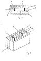
- Fig.1 is a perspective view of one embodiment of the thermally insulating masonry block according to the invention;
- Fig. 2 is a plan view thereof;
- Fig. 3 is an elevation thereof;
- Fig. 4 is a perspective view of a second embodiment of the block according to the invention;
- Fig. 5 is a plan view of the block of Fig. 4;
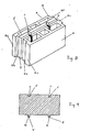
- Fig. 7 is a still further embodiment of the block according to the invention;
- Fig. 8 is a plan view of the block of Fiq. 7;
- Fiq. 9 is an elevation of a further embodiment of an insulating plate;
- Fig. 10 is a Derspective view of a further embodiment of the building block unit of the invention;
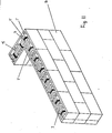
- Fiq. 11 is a perspective view of a wall built with the blocks according to the present invention;
- Fig. 12 is a plan view of the wall of Fig. 11;
- Fig. 13 is a vertical section thereof taken on line XIII-XIII of Fig. 12;
- Fiq. 14 is a perspective view of a further embodiment of the building block according to the invention;
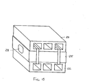
- Fig. 15 is a perspective view of an additional embodiment of a building block according to the invention; and
- Fig. 16 is a perspective view of a further embodiment of a building block according to the invention.
- The insulating masonry block unit shown in Fiqs. 1-3 is constituted by two
conventional building blocks 1 and 2 between which aninsulatinq plate 3 is disposed.Plate 3 projects slightly from the top of the blocks and from their sides, being flush with the bottom. - The 'sandwich' of the two
blocks 1 and 2 and theinsulating plate 3 is held together by twostraps 4 which, as shown, are equally spaced from the ends of the blocks and are located insuitable grooves 5 made in the blocks andcutout 6 made in the top of theplate 3. - The
blocks 1 and 2 may be solid, if weight and cost considerations permit, or they may have one continuous cavity or any number of suitable cavities. One of the blocks may be solid and the other may have cavities. As shown here, block 1 is thicker thanblock 2 but they may also be of the same thickness. While twostraps 4 have been shown, if desired, only one strap or more than two may be provided, spaced as desired. If desired, qroove 5 may be dispensed with. The strap may be of any desired width. - In the block unit shown in Figs. 4-6, the insulatinq plate is sandwiched between conventional building blocks 1', 2' which have three vertically through-
going cavities 7. The straps 4' extend through theouter cavities 7 and thecutout 6 ofplate 3, being disposed in vertical grooves 5', located withincavities 7. Alternatively, the straps 4' extendthrouqh cavities 7 and aboutplate 3 without the addition ofcutout 6 or grooves 5'. It is understood that blocks 1' and 2' may be of any suitable shape and may have any suitable number of cavities of any desired cross-section. The blocks may be identical or one block may be different from or thicker than the other, or be of different material than the other, e.g. concrete and/or ceramics, ytong (T.M.) silicate, plastics, metal, or the like. The insulating plate may be of any suitable plastics having any desired property such as thermal and acoustic insulation and/or impermeability. If desired, it can be made of one material, e.g. foam plastics such as polyurethane or polystyrene, or it may be made of laminations or aggregates of suitable materials, such as tarred paper, rock wool, rubber or plastics or the like, cork, separate or together, the particular insulation being chosen according to the building requirements. An additional layer, such as a lead sheet, may also be added if impermeability to radiation is desired. Such blocks are particularly suitable for use in operating rooms, X-ray rooms and buildings housing scientific experiments or industrial processes using radioactive materials. - In Fig.7 and Fig.8 the insulating plate 3' is of the same dimensions in length and height as blocks 1' and 2'. It is shifted horizontally relative the latter so that it is receded slightly at one end of the blocks, leaving a
space 8 at that end between blocks 1' and 2', and projects for the same distance at theother end 9 of the blocks as shown. Thus, when two block units are juxtaposed, theprojection 9 of one block unit will engage thespace 8 of the adjacent one. - The 'sandwich' block unit is held together by two straps 4' equally spaced from the end of the blocks.
- The block unit illustrated in Figs.7 and 8 facilitates the assembly of the blocks into one rigid layer. However, in order to facilitate also the placement of superposed block units, the insulating
plate 3" is made, as shown in Fig.9, of substantially the same height and length as the blocks, is shifted slightly upwardly relative to the latter and is provided with two leg-like extensions 10 at its bottom and with corresponding cut-outs 11 at its top. As shown in Fig.10, the blocks, whose particular shape will be described hereinafter, andplate 3" are assembled so that the latter extends above the top of the blocks for a distance equal to the depth of cut-outs 11, i.e. the bottom of cut-outs 11 is flush with the top of the blocks and straps 4' extend within said cut-outs and aroundlegs 10. Thus, when two layers of assembled blocks are superposed, thelegs 10 of superposed block units will engage in cut-outs 11 of the block units of the layer below whereby the stretches ofplate 3" between cut-outs 11 will engage in the spaces betweenlegs 10. It is, of course, understood that one or more than two legs and corresponding cut-outs may be provided. - If the features of the masonry block unit described with reference to Figs.7 and 8 and those of Fig.9 are combined, and proper dimensions between
legs 10 and cut-outs 11 are provided, the assembly of a wall which can easily be effected by an unskilled worker attains a stable structure wherein movement of the individual blocks in any direction is prevented. - In known thermal blocks or thermal insulation of buildings, one of the important considerations is the prevention of damage to the insulation. It is obvious from the above description and the drawings that, according to the invention, the
blocks 1 and 2 provide means for preventing damage to the insulatingplate 3. However, the handling of building blocks in a standard manner for transport is often effected with the aid of hydraulic clamps which may press a layer of the block units so that the insulatingplates 3 are damaged at their projecting edges. In order to prevent this and to increase the possibility of immovability of adjacent and superposed block units relative each other, the building blocks may be formed as shown in Fig. 10. - Each
block flange 12a,13a respectively and at the other with a cut-away portion 12b,13b, respectively, the latter being of substantially the same width as flanges 12a13a respectively, and being staggered relative thereto. The shape of insulatingplate 3" is that described with reference to Fig.9. In this manner the block units may be justaposed so thatflanges 12a,13a of a first unit extend into cut-away portions 12b,13b respectively of the adjacent second block unit andprojection 9 of the latter extends intospace 8 of said first block unit. Furthermore, theportions 12c, 13c next to cut-away portions 12b, 13b respectively protect the vertically extendingprojections 9 of the insulatingplate 3" during transport. - If desired,
flanges 12a, 13a can be of any suitable width, smaller or of different shape than cut-away portions 12b, 13b. When such block units are juxtaposed, a space may be created between them, but the insulating plates will touch each other. - The insulating plate may also be made shorter on both ends of the blocks to protect the insulating plate during transport of the block units. In this case it will be necessary to insert a piece of insulatina plate between two juxtaposed block units in the spaces left by the insulating plate between the blocks.
- In Figs. 11 to 13, a wall is built from the blocks shown in Figs. 7 and 8. After the base layer B of the blocks is placed in position, and preferably, affixed to the foundation by mortar, as known, a second layer is superimposed in staggered relation in such a manner that straps 4' of the second layer are in vertical alignment with those of the base layer.
- The straps of the two layers may be glued, welded, clamped or heat-sealed to each other, depending on the material of which the straps are constituted. It is preferred to make straps 4' of a thermoplastic plastics so that the blocks can be connected to each other by means of
short strips 10 which are attached by glue or heat-sealing between the top of the straps 4' of the blocks of a lower stretch and the bottom of the straps 4' of the blocks of a superposed stretch at both sides of the assembled blocks. The attachment is effected by means of a suitable forklike clamp from above each layer, which extends through the cavities of the block. The straps of the blocks are thus rigidly attached to each other so that no mortar or the like is required between lasers of blocks, and no finishing operations are necessary in the erected wall. Alternatively, straps 4' may comprise two or more materials, instead of a single material. The wall of the present invention may be made by conventional methods, including the use of mortar, with the building blocks of the present invention. - If desired, concrete may be poured into several or all of the cavities of the block unit, as in conventional building construction. Also, if desired, the outsides of the wall may be covered with mortar, likewise as in conventional building methods. However, both these procedures are not necessary, with the block according to the invention, thus providing a less costly building method.
- In order to ensure a perfect thermal bridge all around the building, the corner is made in such a manner, as can be seen in Figs. 11 and 12, that half the length of block 2', which corresponds to the thickness of the standard masonry block according to the invention, is cut off at 11 and a standard block is placed against said cut-off part 11 perpendicular to it, so that plate 3' of one block is in engagement. The side wall of block 1' placed in a corner is provided with an extention 11' in such a manner that it covers the edge of
plate 3, i.e. extension 11'fills space 8. - If desired, any other suitable corner construction can be effected which will secure a perfect thermal bridge in the corners.
- In general, it can be appreciated that when it is desired to use mortar between layers of block units, the insulating plate has to extend slightly above and beyond the sides of the building blocks to assure a thermal bridge between the layers.
- In the case where the straps are connected to each other and no mortar is used, the insulating plates of the units touch each other and form a thermal bridge.
- It will be appreciated that the insulating plate in the building block of the present invention need not be a shallow plate. Referring to the embodiment of Fig. 14, there is shown a building block unit constituted by two
conventional building blocks building block 24 is disposed. The block of Fig. 14 is useful when it is desired to provide a building block unit of greater than usual width, when the amount of insulation required between blocks is particularly large, and so on. The insulating plate may be formed withcavities 26, as illustrated, in order to save material and make the finished block unit lighter in weight.Cavities 26 can be of any size, shape or number desired. Alternatively, the insulating block may be a solid block of foamed plastic, styrofoam or other insulating material with no cavities. - With reference to Fig. 15, there is shown an alternate embodiment of the building block of Fig. 14. In this embodiment, the insulating material 24' defines a
cavity 28 in a plane perpendicular to the cavities inblocks Cavity 28 permits passage of various pipes, i.e. water, steam, electricity, through the finished wall. In addition, it provides insulation for these pipes, rather than necessitating the addition of insulating materials, as in conventional building blocks. - Referring now to Fig. 16 there is shown an alternate embodiment of the building block of the present invention comprising a single
conventional building block 30 and an insulatingplate 32 tied together by straps 34. Insulatingplate 32 may comprise a plate shaped like a conventional building block, as illustrated, with or withoutcavities 36, or a narrower plate of any design. The building block of Fig. 16 is particularly useful as a ceiling block or as an insulating wall behind a decorative brick or other wall. Where insulatingplate 32 comprises a block of foamed plastic, an additional insulating layer for sound or other insulation can be sandwiched betweenplate 32 andblock 32, as described above. - It will be appreciated that in the embodiment of Fig. 16,
plate 32 can be hollow, if desired, or solid, instead of having cavities. Straps 34 may pass around the periphery ofplate 32 andblock 30, instead of through cavities therein, to tie the two together. - It will be appreciated by those skilled in the art that the invention is not limited to what has been shown and described hereinabove by way of example. Rather, the scope of the invention is limited solely by the claims which follow.
Claims (21)
1. A thermally insulating masonry block constituted by a sandwich of at least two building blocks between which a plate of insulating material is interposed, the sandwich being tied together by at least one strap.
2. A thermally insulating masonry block unit as claimed in Claim 1, wherein the building blocks are of conventional material and construction.
3. A thermally insulating masonry block unit as claimed in Claim 1 or 2 wherein the building blocks have at least one throughgoing cavity, the strap extending through said cavity.
4. A thermally insulating masonry block unit as claimed in any of Claims 1 to 3 wherein two or more straps are used to tie said sandwich together.
5. A thermally insulating masonry block unit as claimed in any of Claims 1 to 4 wherein the building blocks have two or more throughgoing cavities, the straps extending through one or more of the cavities.
6. A thermally insulating masonry block unit as claimed in any of claims 1 to 5 wherein said plate is of the same height and length as said blocks.
7. A thermally insulating masonry block unit as claimed in any of Claims 1 to 5 wherein said plate is of such dimensions that it protrudes slightly from the top and from one or both 'sides of the building blocks.
8. A thermally insulating masonry block unit as claimed in any of Claims 1 to 4 and 6 and 7 wherein the strap surrounds said blocks.
9. A thermally insulating masonry block unit as claimed in Claims 1 to 8 wherein notches are made for the straps in the insulating plate and blocks.
10. A thermally insulating masonry block unit as claimed in any of the preceding claims, wherein said plate is made of one integral unit.
11. A thermally insulating masonry block unit as claimed in any of Claims 1 to 9 wherein said plate is made of layers, each having the same or different insulating properties.
12. A thermally insulating masonry block unit as claimed in any of the preceding claims wherein the plate is shifted horizontally relative the building blocks.
13. A thermally insulating masonry block unit as claimed in any of Claims 1 to 6 and 8 to 11, wherein the plate is shifted vertically relative the building blocks and is provided at its bottom with integral leg-like extensions and at its top with corresponding cut-outs, the bottom of said extensions and the bottom of said cut-outs being substantially flush with the bottom and top, respectively, of the building blocks.
14. A thermally insulating masonry block unit as claimed in Claim 13 wherein the building blocks are made inteqral at one adjacent end with a vertically extending projecting flanqe, and at the other adjacent end with a vertically extending cut-away portion.
15. A thermally insulatinq masonry block unit as claimed in claim 1 wherein said insulatinq plate defines at least one cavity therethrouqh.
16. A thermally insulating masonry block unit as claimed in claim 15 and wherein said cavity is arranged to accommodate piping.
17. A method of making an insulating masonry block unit comprising the steps of interposing a plate of insulating material between two building blocks and tying the blocks and insulating plate together by at least one stran.
18. A method of erecting a wall from insulatinq masonry block units constituted by a sandwich of at least two building blocks between which a plate of insulating material is interposed, the sandwich being tied together by at least one strap, the method comprising the steps of placing a first base layer of blocks, disposing a second layer of blocks on said base layer so that said straps are vertically aligned, and thereafter sealing said vertically aligned straps to one another.
19. A method as claimed in Claim 18 wherein said step of sealing comprises gluing, heat-sealing, welding or bridging each two of said vertically aligned straps by a bridging strip.
20, A thermally insulating masonry block comprising a conventional building block and a block of insulating material, the two blocks being tied together by at least one strap.
21 . A thermally insulating masonry block as claimed in claim 19 and further comprising a plate of insulating material interposed between said building block and said block of insulating material.
Applications Claiming Priority (2)
| Application Number | Priority Date | Filing Date | Title |
|---|---|---|---|
| IL75758 | 1985-07-10 | ||
| IL75758A IL75758A (en) | 1985-07-10 | 1985-07-10 | Thermally-insulating masonry block,method for manufacturing such a block and method of building a wall of such blocks |
Publications (2)
| Publication Number | Publication Date |
|---|---|
| EP0209993A2 true EP0209993A2 (en) | 1987-01-28 |
| EP0209993A3 EP0209993A3 (en) | 1987-12-23 |
Family
ID=11056056
Family Applications (1)
| Application Number | Title | Priority Date | Filing Date |
|---|---|---|---|
| EP86304879A Withdrawn EP0209993A3 (en) | 1985-07-10 | 1986-06-24 | A thermally insulating masonry block, a method for manufacturing such a block, and a method of building a wall of such blocks |
Country Status (5)
| Country | Link |
|---|---|
| US (1) | US4802318A (en) |
| EP (1) | EP0209993A3 (en) |
| AU (1) | AU5986786A (en) |
| IL (1) | IL75758A (en) |
| ZA (1) | ZA865106B (en) |
Cited By (11)
| Publication number | Priority date | Publication date | Assignee | Title |
|---|---|---|---|---|
| GB2192211A (en) * | 1986-07-02 | 1988-01-06 | Concrete Masonry Limited | Building block with insulation layer |
| GB2224761B (en) * | 1988-10-10 | 1993-04-21 | Anthony David Precey | An acoustic screen |
| EP0872608A3 (en) * | 1997-04-16 | 1999-08-04 | Rudolf Schmaranz | Construction element |
| DE10315649A1 (en) * | 2003-04-04 | 2004-10-28 | Manfred Niedermeyer | Brick for creating of heat and soundproofed structures of buildings has outer shell, inner shell and insulating section formed as individual components assembled into rigid one-piece sandwich |
| EP1552076A4 (en) * | 2002-06-27 | 2007-04-04 | Eliyahu Maimon | Modular wall segments and method of making such segments |
| WO2012172133A1 (en) * | 2011-06-16 | 2012-12-20 | Arriola Serrano Ana | Construction block and method for constructing said block |
| WO2013098448A1 (en) * | 2011-12-26 | 2013-07-04 | ROS AROCA, Joaquín Ángel | Energy-efficient climate wall formed by multilayer blocks that can be assembled together |
| CN104631692A (en) * | 2015-02-04 | 2015-05-20 | 许浒 | Split buckling type self heat-insulation building block and manufacturing method thereof |
| WO2017055630A1 (en) * | 2015-10-01 | 2017-04-06 | Universiteit Gent | Structural block with increased insulation properties |
| DE102017103625A1 (en) * | 2017-02-22 | 2018-02-22 | Srz Schutzrechte Verwaltungs-Gmbh | building block |
| EP4056781A1 (en) | 2021-03-10 | 2022-09-14 | Grzegorz Gwózdz | Multilayer building block |
Families Citing this family (31)
| Publication number | Priority date | Publication date | Assignee | Title |
|---|---|---|---|---|
| AU589804B2 (en) * | 1986-09-19 | 1989-10-19 | John Emil Rayner | Insulated concrete brick or block |
| AU625548B2 (en) * | 1989-04-05 | 1992-07-16 | John Emil Rayner | Improved insulated building element |
| US5154032A (en) * | 1991-02-26 | 1992-10-13 | Firma Hermann Uhl | Building block system |
| US5371990A (en) * | 1992-08-11 | 1994-12-13 | Salahuddin; Fareed-M. | Element based foam and concrete modular wall construction and method and apparatus therefor |
| US5474405A (en) * | 1993-03-31 | 1995-12-12 | Societe Civile Des Brevets Henri C. Vidal | Low elevation wall construction |
| US5709061A (en) * | 1994-06-28 | 1998-01-20 | Iowa State University Research Foundation, Inc. | Structural connector for a sandwich construction unit |
| US5983585A (en) * | 1997-02-04 | 1999-11-16 | Spakousky; John | Building block with insulating center portion |
| US6978581B1 (en) | 1997-02-04 | 2005-12-27 | Pentstar Corporation | Composite building block with connective structure |
| ES2158759B1 (en) * | 1998-10-05 | 2002-05-01 | Univ Cantabria | CERAMIC ELEMENT OF TABIQUERIA AND CLOSURE, IN PARTICULAR ELEMENT OF ACOUSTIC AND / OR THERMAL INSULATION. |
| US6122881A (en) * | 1998-10-08 | 2000-09-26 | Aubertot; Christophe | Lengthwise extrusion of facing bricks to create interlocking profiles |
| US6205726B1 (en) * | 1999-05-05 | 2001-03-27 | Theodore A. Hoadley | Insulated masonry block and wall |
| US6223493B1 (en) * | 1999-12-01 | 2001-05-01 | John Robert Ruggeri | Self-aligning building blocks |
| ES2183700A1 (en) * | 2000-12-27 | 2003-03-16 | Univ Cantabria | Ceramic partitioning and closure element for sound and/or heat insulation |
| IL141467A0 (en) * | 2001-02-15 | 2002-03-10 | Industrial walls | |
| US20040035068A1 (en) * | 2002-01-02 | 2004-02-26 | Maimon Eliyahu | Modular wall segments and method of making such segments |
| US6843034B2 (en) * | 2002-05-31 | 2005-01-18 | Mcdonald Barry L. | Masonry block locking device |
| US6665994B1 (en) | 2002-06-07 | 2003-12-23 | John Robert Ruggeri | Self-aligning building blocks |
| KR100505836B1 (en) * | 2003-08-28 | 2005-08-02 | 주식회사 제이지비 | Architectural brick |
| US20080202051A1 (en) * | 2007-02-28 | 2008-08-28 | Roehrig Robert C | Concrete block system |
| EP2116663A1 (en) * | 2008-05-08 | 2009-11-11 | Stamford Consulting Limited | Insulating composite block for the building industry, and method of manufacturing said block |
| US8091307B2 (en) * | 2009-08-18 | 2012-01-10 | King Abdulaziz University | Convection baffle for hollow blocks |
| CN102535730A (en) * | 2012-02-15 | 2012-07-04 | 安徽工业大学 | Building block compositely filled with phase change material and thermal insulation material |
| US20140196397A1 (en) * | 2013-01-17 | 2014-07-17 | Tom Sourlis | Insulated building block and wall structure |
| US9650784B2 (en) * | 2014-02-04 | 2017-05-16 | Thermagreen Systems, Inc. | Modular units for insulating concrete forms |
| US9447578B2 (en) | 2015-01-02 | 2016-09-20 | Richard Nelson DeBoer | Modular block wall system |
| CN104775561B (en) * | 2015-03-16 | 2016-09-14 | 上海模卡建筑工程科技发展有限公司 | Self-heat conserving high-strength assembling building block |
| FR3047501B1 (en) * | 2016-02-09 | 2021-04-02 | G2S Tech S A | ISOLATED BUILDING BLOCK BETWEEN PLANELLES WITH HOLDING STRUCTURE OF THE PLANELLES. |
| RU170258U1 (en) * | 2016-11-29 | 2017-04-18 | Федеральное государственное бюджетное образовательное учреждение высшего образования "Воронежский государственный технический университет" | BUILDING BLOCK |
| CN110593482A (en) * | 2019-06-21 | 2019-12-20 | 河南兴安新型建筑材料有限公司 | Novel assembly type building heat-insulation building block system and assembly method thereof |
| US20220364360A1 (en) * | 2019-10-23 | 2022-11-17 | Spyderblock | Concrete formwork system with insulating panels, connection elements and assembly method |
| US12371899B2 (en) * | 2022-12-26 | 2025-07-29 | Mauro Nicolas Querejeta | Brick clip to build double walls in a construction site |
Family Cites Families (13)
| Publication number | Priority date | Publication date | Assignee | Title |
|---|---|---|---|---|
| FR960158A (en) * | 1950-04-14 | |||
| AT86182B (en) * | 1919-09-10 | 1921-11-10 | Franz Steigel | Shaped stone. |
| FR1375968A (en) * | 1963-09-18 | 1964-10-23 | Beton Box Ag | building element |
| US3559361A (en) * | 1968-06-04 | 1971-02-02 | Sarros Construction Co Inc | Method for construction |
| US3546833A (en) * | 1968-10-08 | 1970-12-15 | Arnold Perreton | Insulated building block construction |
| FR2197104A2 (en) * | 1972-08-23 | 1974-03-22 | Bordini Yves | |
| US3815733A (en) * | 1972-10-19 | 1974-06-11 | T Roberts | Construction unit assembly |
| DE2347091A1 (en) * | 1973-09-19 | 1975-04-24 | Erich Dr Cziesielski | Ventilated sandwich wall panel - has insulating layer, supports and plate combined into outer panel supporting frame |
| DE2440466A1 (en) * | 1974-08-23 | 1976-03-04 | Siegfried Gebhart | Hollow cavity brick with internal insulation layer - has symmetrical cross section with insulating layer between brick halves |
| GB1525031A (en) * | 1975-04-18 | 1978-09-20 | Magerle O | Building block |
| US4616459A (en) * | 1981-05-29 | 1986-10-14 | Calvin Shubow | Building construction using hollow core wall |
| US4584043A (en) * | 1983-08-15 | 1986-04-22 | Monte Riefler | Insulated concrete block assembly and method of making the same |
| US4574550A (en) * | 1984-05-21 | 1986-03-11 | Jack Maschhoff | Building wall and insulation assembly |
-
1985
- 1985-07-10 IL IL75758A patent/IL75758A/en not_active IP Right Cessation
-
1986
- 1986-06-24 EP EP86304879A patent/EP0209993A3/en not_active Withdrawn
- 1986-07-09 ZA ZA865106A patent/ZA865106B/en unknown
- 1986-07-09 AU AU59867/86A patent/AU5986786A/en not_active Abandoned
-
1987
- 1987-08-06 US US07/083,034 patent/US4802318A/en not_active Expired - Fee Related
Cited By (13)
| Publication number | Priority date | Publication date | Assignee | Title |
|---|---|---|---|---|
| GB2192211A (en) * | 1986-07-02 | 1988-01-06 | Concrete Masonry Limited | Building block with insulation layer |
| GB2224761B (en) * | 1988-10-10 | 1993-04-21 | Anthony David Precey | An acoustic screen |
| EP0872608A3 (en) * | 1997-04-16 | 1999-08-04 | Rudolf Schmaranz | Construction element |
| EP1552076A4 (en) * | 2002-06-27 | 2007-04-04 | Eliyahu Maimon | Modular wall segments and method of making such segments |
| DE10315649A1 (en) * | 2003-04-04 | 2004-10-28 | Manfred Niedermeyer | Brick for creating of heat and soundproofed structures of buildings has outer shell, inner shell and insulating section formed as individual components assembled into rigid one-piece sandwich |
| ES2398555A1 (en) * | 2011-06-16 | 2013-03-20 | Ana ARRIOLA SERRANO | Construction block and method for constructing said block |
| WO2012172133A1 (en) * | 2011-06-16 | 2012-12-20 | Arriola Serrano Ana | Construction block and method for constructing said block |
| WO2013098448A1 (en) * | 2011-12-26 | 2013-07-04 | ROS AROCA, Joaquín Ángel | Energy-efficient climate wall formed by multilayer blocks that can be assembled together |
| CN104631692A (en) * | 2015-02-04 | 2015-05-20 | 许浒 | Split buckling type self heat-insulation building block and manufacturing method thereof |
| WO2017055630A1 (en) * | 2015-10-01 | 2017-04-06 | Universiteit Gent | Structural block with increased insulation properties |
| US10563397B2 (en) | 2015-10-01 | 2020-02-18 | Universiteit Gent | Structural block with increased insulation properties |
| DE102017103625A1 (en) * | 2017-02-22 | 2018-02-22 | Srz Schutzrechte Verwaltungs-Gmbh | building block |
| EP4056781A1 (en) | 2021-03-10 | 2022-09-14 | Grzegorz Gwózdz | Multilayer building block |
Also Published As
| Publication number | Publication date |
|---|---|
| IL75758A (en) | 1988-02-29 |
| US4802318A (en) | 1989-02-07 |
| EP0209993A3 (en) | 1987-12-23 |
| AU5986786A (en) | 1987-01-15 |
| ZA865106B (en) | 1987-03-25 |
| IL75758A0 (en) | 1985-11-29 |
Similar Documents
| Publication | Publication Date | Title |
|---|---|---|
| EP0209993A2 (en) | A thermally insulating masonry block, a method for manufacturing such a block, and a method of building a wall of such blocks | |
| US5809727A (en) | Web member for concrete form walls | |
| US4016693A (en) | Insulated masonry block | |
| EP0694102B1 (en) | Concrete form walls | |
| US3344572A (en) | Concrete building structures with prelaminated plasterboard facing sheets | |
| US5038541A (en) | Polymer building wall form construction | |
| US4087072A (en) | Form means for fabricating pre-cast structural panels | |
| EP0163117B1 (en) | Bettered, high thermal, and/or sound insulating modular elements suitable for buildings | |
| US3435580A (en) | Insulated,reinforced concrete,panel-type building unit | |
| US4015387A (en) | Prefabricated structural elements for partitions and walls of buildings and partitions and walls consisting of such elements | |
| US4324080A (en) | Thermally insulative cementitious block modules and method of making same | |
| US4566238A (en) | Energy conserving concrete masonry unit, wall construction and method | |
| US4187651A (en) | Method for manufacturing thermally insulated buildings, construction elements suitable for application in this method and a method of manufacturing the building construction elements | |
| US4073111A (en) | Insulated masonry block | |
| KR101731493B1 (en) | Insulation and bearing panel and its manufacturing and installation method | |
| US5755067A (en) | Method of overlapping composite building construction with superior thermal insulation efficiency | |
| WO1993023632A1 (en) | Wall for a building, method for erecting such a wall and element therefor | |
| EP0591849B1 (en) | Insulated wall panel | |
| JPH02225749A (en) | Steel plate-framed and reinforced concrete wall column for building | |
| US4142338A (en) | Construction unit | |
| US20060016143A1 (en) | Insulated tile and stone block wall | |
| RU2167248C1 (en) | Building frame structure | |
| GB1570761A (en) | Building a construction member | |
| US2447916A (en) | Building wall | |
| US4107899A (en) | Load-bearing walls and similar structures |
Legal Events
| Date | Code | Title | Description |
|---|---|---|---|
| PUAI | Public reference made under article 153(3) epc to a published international application that has entered the european phase |
Free format text: ORIGINAL CODE: 0009012 |
|
| AK | Designated contracting states |
Kind code of ref document: A2 Designated state(s): AT BE CH DE FR GB IT LI LU NL SE |
|
| PUAL | Search report despatched |
Free format text: ORIGINAL CODE: 0009013 |
|
| AK | Designated contracting states |
Kind code of ref document: A3 Designated state(s): AT BE CH DE FR GB IT LI LU NL SE |
|
| 17P | Request for examination filed |
Effective date: 19880609 |
|
| STAA | Information on the status of an ep patent application or granted ep patent |
Free format text: STATUS: THE APPLICATION IS DEEMED TO BE WITHDRAWN |
|
| 18D | Application deemed to be withdrawn |
Effective date: 19900103 |