EP0209170B1 - Anlage zur Kühlung von Produkten unter Vakuum - Google Patents
Anlage zur Kühlung von Produkten unter Vakuum Download PDFInfo
- Publication number
- EP0209170B1 EP0209170B1 EP86201039A EP86201039A EP0209170B1 EP 0209170 B1 EP0209170 B1 EP 0209170B1 EP 86201039 A EP86201039 A EP 86201039A EP 86201039 A EP86201039 A EP 86201039A EP 0209170 B1 EP0209170 B1 EP 0209170B1
- Authority
- EP
- European Patent Office
- Prior art keywords
- vessel
- throttle valve
- refrigerant
- condenser
- vacuum
- Prior art date
- Legal status (The legal status is an assumption and is not a legal conclusion. Google has not performed a legal analysis and makes no representation as to the accuracy of the status listed.)
- Expired
Links
- 238000009434 installation Methods 0.000 title claims abstract description 17
- XLYOFNOQVPJJNP-UHFFFAOYSA-N water Substances O XLYOFNOQVPJJNP-UHFFFAOYSA-N 0.000 claims abstract description 34
- 239000003507 refrigerant Substances 0.000 claims abstract description 31
- 239000007788 liquid Substances 0.000 claims abstract description 23
- 241000208822 Lactuca Species 0.000 claims abstract description 3
- 235000003228 Lactuca sativa Nutrition 0.000 claims abstract description 3
- 238000000034 method Methods 0.000 abstract description 4
- 238000001704 evaporation Methods 0.000 abstract description 2
- 230000008020 evaporation Effects 0.000 abstract description 2
- 239000007789 gas Substances 0.000 description 8
- 238000005057 refrigeration Methods 0.000 description 8
- 239000000203 mixture Substances 0.000 description 4
- 238000001816 cooling Methods 0.000 description 2
- 238000005273 aeration Methods 0.000 description 1
- 230000015572 biosynthetic process Effects 0.000 description 1
- 238000009835 boiling Methods 0.000 description 1
- 239000011248 coating agent Substances 0.000 description 1
- 238000000576 coating method Methods 0.000 description 1
- 238000010586 diagram Methods 0.000 description 1
- 230000000694 effects Effects 0.000 description 1
- 238000004519 manufacturing process Methods 0.000 description 1
- 239000000463 material Substances 0.000 description 1
Images
Classifications
-
- F—MECHANICAL ENGINEERING; LIGHTING; HEATING; WEAPONS; BLASTING
- F25—REFRIGERATION OR COOLING; COMBINED HEATING AND REFRIGERATION SYSTEMS; HEAT PUMP SYSTEMS; MANUFACTURE OR STORAGE OF ICE; LIQUEFACTION SOLIDIFICATION OF GASES
- F25D—REFRIGERATORS; COLD ROOMS; ICE-BOXES; COOLING OR FREEZING APPARATUS NOT OTHERWISE PROVIDED FOR
- F25D31/00—Other cooling or freezing apparatus
-
- F—MECHANICAL ENGINEERING; LIGHTING; HEATING; WEAPONS; BLASTING
- F25—REFRIGERATION OR COOLING; COMBINED HEATING AND REFRIGERATION SYSTEMS; HEAT PUMP SYSTEMS; MANUFACTURE OR STORAGE OF ICE; LIQUEFACTION SOLIDIFICATION OF GASES
- F25B—REFRIGERATION MACHINES, PLANTS OR SYSTEMS; COMBINED HEATING AND REFRIGERATION SYSTEMS; HEAT PUMP SYSTEMS
- F25B1/00—Compression machines, plants or systems with non-reversible cycle
Definitions
- the invention relates to an installation for refrigerating products under vacuum, particularly products consisting mainly of water, such as lettuce, which installation comprises a closable vessel for the products, one or more vacuum pumps adapted to produce a vacuum in the interior of the vessel, a water vapour condenser disposed in the vessel through which a refrigerant can be passed, and refrigerating unit comprising a compressor, a condenser and a throttle valve, disposed outside of the vessel and an evaporator being formed by said water vapour condenser disposed in the vessel, whereby a low pressure separator is provided for liquid and vaporous refrigerant, the suction pipe of the compressor and the outlet pipe of the throttle valve, as well as the inlet and outlet pipes of the water vapour condenser, being connected with the low pressure separator, whereby in the inlet pipe means are present for controlling the feed of liquid refrigerant to the water vapour condenser, whereby the compressor is brought into action, with the throttle valve open, approximately with the
- the desired boiling temperature (flash point) of the water is obtained by lowering the pressure in the installation with the aid of the vacuum pump or pumps. Heat is required in evaporate water, and this will be taken from the product.
- the vessel After the installation has been loaded up, the vessel is closed.
- the vacuum pump is operated until the water in the product is evaporated (flash point).
- the water vapour formed is condensed on the water vapour condenser, while the vacuum pump draws off the non-condensable gases, such as air.
- the refrigerated load can then be replaced by a new load for refrigeration.
- the vacuum pump remains in operation even when the flash point has been reached. From that moment on the compressor is also normally brought into action in order to pass refrigerant through the condenser and in condense the water vapour.
- a cycle of 20 minutes comprising 8 minutes for producting the vacuum, 8 minutes for the refrigeration, and 4 minutes for loading and unloading.
- the vacuum pump then operates for 16 minutes and the refrigerating unit for 8 minutes.
- the invention seeks to modify the known method in such a manner that a much smaller and therefore less expensive refrigerating unit can be used, and the compressor and the refrigerant condenser may have the half size and the efficiency of the vacuum pump(s) during vacation can be highly improved.
- the cold stock is formed by
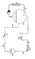
- the water vapour condenser disposed in the vacuum tank is designated 1; it is generally divided into a plurality of condenser sections. From this condenser 1 a pipe 2 extends to the top gas part of a liquid-gas separator 3 for a refrigerant, for example R 22.
- a pump 5 is provided in this pipe 4. This pump 5 circulates refrigerant through 1, 2, 3, 4 and 5.
- the other branch is formed by a suction pipe 6 connected to the end of the separator 3, a compressor 7, a pressure pipe 8, a refrigerant condenser 9, a pipe 10, a reservoir 11 for liquid refrigerant, a pipe 12, a throttle valve 13 for liquid refrigerant, and a pipe 14 returning to the gas part of the separator 3.
- the compressor 7 is also put into action.
- This compressor 7 ensures that liquid refrigerant contained in the high-pressure vessel 11, and having for example a temperature of +35 ° C, is conducted to the low-pressure vessel 3.
- the temperature of the refrigerant is thus lowered to, for example, -5 ° C or even lower, for example -20 ° .
- the pipes of the water vapour condenser 1 are thereby brought for example to a temperature of -5 ° or even lower.
- the vapour pressure of the water vapour in the installation thus falls to below 4 millibars. This means that with a pressure of about 46 millibars in the vessel the vacuum pump must draw in a gas mixture consisting of about 10% water vapour and 90% air. The rate at which the vacuum is produced is thereby approximately doubled, in the ratio of 50 : 90.
- the pipes of the water vapour condenser 1 When the pipes of the water vapour condenser 1 are not precooled, they have a temperature of, for example, +20 ° , corresponding to a pressure of the water vapour in the gas mixture of 23 millibars. This means that when the total pressure has been reduced to 46 millibars by the vacuum pump the mixture flowing over the pipes of the water vapour condenser 1 then consists of 50 parts by volume of air.
- the mixture consists of 10% water vapour and 90% air.
- the water vapour is deposited on the pipes of the condenser in the form of ice.
- a coating of ice is thus formed.
- the adhering water drops also freeze, assisted by the low temperature of the material of the pipes.
- the vaporous refrigerant extracted from the separator 3 by the compressor 7 via the pipe 6 consists solely of vapour generated by heat from the product.
- the vapour compressed by the compressor 7 is condensed in the condenser 9 and then deposited as a liquid in the high-pressure vessel 11, where it is kept for the next cycle.
- a conventional refrigeration circuit is in fact divided into two incomplete circuits.
- the compressor 7 and the condenser 9 can be about half the size in comparison with a conventional vacuum refrigeration installation, as calculated in the following example.
- the enthalpy of the liquid R22 is equal to 243 kJ/kg.
- the enthalpy of R22 gas at -5 ° C is 403 kJ/kg.
Landscapes
- Engineering & Computer Science (AREA)
- General Engineering & Computer Science (AREA)
- Physics & Mathematics (AREA)
- Mechanical Engineering (AREA)
- Thermal Sciences (AREA)
- Combustion & Propulsion (AREA)
- Chemical & Material Sciences (AREA)
- Manufacture Of Macromolecular Shaped Articles (AREA)
- Crystals, And After-Treatments Of Crystals (AREA)
- Vacuum Packaging (AREA)
- Polyesters Or Polycarbonates (AREA)
- Sorption Type Refrigeration Machines (AREA)
- Vaporization, Distillation, Condensation, Sublimation, And Cold Traps (AREA)
Claims (1)
- Anlage zur Kühlung von Produkten unter Vakuum, besonders für Produkte, die hauptsächlich aus Wasser bestehen, wie Salat, wobei die Anlage einen verschliessbaren Behälter für die Produkte umfasst, eine oder mehrere Vakuumpumpen, die so ausgelegt sind, dass sie im Inneren des Behälters ein Vakuum erzeugen können, einen in dem Behälter angeordneten Wasserdampf-Kondensator (1), durch den ein Kühlmittel geleitet werden kann, sowie eine Kühleinheit, die einen Kompressor (7), einen Kondensator (9) und ein Drosselventil (13) aufweist, die ausserhalb des Behälters angeordnet sind, sowie einen Verdampfer, der gebildet wird durch den erwähnten, in dem Behälter angeordneten Wasserdampf-Kondensator (1), wobei ein Niederdruck-Separator (3) für flüssiges und dampfförmiges Kühlmittel vorgesehen ist, wobei das Saugrohr (6) des Kompressor (7) und das Ableitungsrohr (14) des Drosselventils (13) sowie die Einlass- und Auslassrohre (4 bzw. 2) des Wasserdampf-Kondensators (1) mit dem Niederdruck-Separator (3) verbunden sind, und wobei in dem Einlassrohr (4) Mittel (5) zur Steuerung der Zufuhr von flüssigem Kühlmittel zum Wasserdampf-Kondensator (1) vorhanden sind, wodurch der Kompressor (7) eingeschaltet wird bei geöffnetem Drosselventil (13) ungefähr gleichzeitig mit der Vakuumpumpe bzw. -pumpen, dadurch gekennzeichnet, dass ein Hochdruck-Behälter (11) für flüssiges Kühlmittel zwischen dem Kühlmittel-Kondensator (9) und dem Drosselventil (13) angeordnet ist und dass eine Steuerung des Drosselventils (13) vorgesehen ist, so dass das Drosselventil (13) beim Erreichen des Verdampfungspunktes des Wassers in dem Produkt geschlossen wird.
Priority Applications (1)
| Application Number | Priority Date | Filing Date | Title |
|---|---|---|---|
| AT86201039T ATE40000T1 (de) | 1985-07-10 | 1986-06-13 | Anlage zur kuehlung von produkten unter vakuum. |
Applications Claiming Priority (2)
| Application Number | Priority Date | Filing Date | Title |
|---|---|---|---|
| NL8501978A NL8501978A (nl) | 1985-07-10 | 1985-07-10 | Installatie voor het onder vacuum koelen van produkten. |
| NL8501978 | 1985-07-10 |
Publications (2)
| Publication Number | Publication Date |
|---|---|
| EP0209170A1 EP0209170A1 (de) | 1987-01-21 |
| EP0209170B1 true EP0209170B1 (de) | 1989-01-11 |
Family
ID=19846276
Family Applications (1)
| Application Number | Title | Priority Date | Filing Date |
|---|---|---|---|
| EP86201039A Expired EP0209170B1 (de) | 1985-07-10 | 1986-06-13 | Anlage zur Kühlung von Produkten unter Vakuum |
Country Status (5)
| Country | Link |
|---|---|
| EP (1) | EP0209170B1 (de) |
| AT (1) | ATE40000T1 (de) |
| DE (1) | DE3661776D1 (de) |
| ES (1) | ES8706932A1 (de) |
| NL (1) | NL8501978A (de) |
Families Citing this family (1)
| Publication number | Priority date | Publication date | Assignee | Title |
|---|---|---|---|---|
| NL1010903C2 (nl) | 1998-12-24 | 2000-06-27 | York Inham Refrigeration B V | Werkwijze en inrichting voor het ladingsgewijs vacuümkoelen van producten. |
Family Cites Families (2)
| Publication number | Priority date | Publication date | Assignee | Title |
|---|---|---|---|---|
| US2748576A (en) * | 1952-10-28 | 1956-06-05 | Sr Theodore J Peukert | Fruit and vegetable cooler |
| US3319434A (en) * | 1966-03-14 | 1967-05-16 | Air Reduction | Low temperature refrigeration and gas storage |
-
1985
- 1985-07-10 NL NL8501978A patent/NL8501978A/nl not_active Application Discontinuation
-
1986
- 1986-06-13 AT AT86201039T patent/ATE40000T1/de not_active IP Right Cessation
- 1986-06-13 DE DE8686201039T patent/DE3661776D1/de not_active Expired
- 1986-06-13 EP EP86201039A patent/EP0209170B1/de not_active Expired
- 1986-06-24 ES ES556521A patent/ES8706932A1/es not_active Expired
Also Published As
| Publication number | Publication date |
|---|---|
| ES556521A0 (es) | 1987-07-16 |
| NL8501978A (nl) | 1987-02-02 |
| DE3661776D1 (en) | 1989-02-16 |
| ATE40000T1 (de) | 1989-01-15 |
| ES8706932A1 (es) | 1987-07-16 |
| EP0209170A1 (de) | 1987-01-21 |
Similar Documents
| Publication | Publication Date | Title |
|---|---|---|
| US4886534A (en) | Process for apparatus for cryogenic cooling using liquid carbon dioxide as a refrigerating agent | |
| US4224801A (en) | Stored cryogenic refrigeration | |
| US1933257A (en) | Method and apparatus for speed freezing | |
| KR100454442B1 (ko) | 공급 스트림으로부터 이산화탄소를 회수하는 방법 | |
| US20010023594A1 (en) | Refrigeration system | |
| EP0529293B1 (de) | Kälteanlage | |
| US4535597A (en) | Fast cycle water vapor cryopump | |
| US3922875A (en) | Refrigeration system with auxiliary defrost heat tank | |
| US4223537A (en) | Air cooled centrifugal water chiller with refrigerant storage means | |
| US3882689A (en) | Flashing liquid refrigerant and accumulating unvaporized portions at different levels of a single vessel | |
| US2146797A (en) | Refrigerating apparatus | |
| DE3174599D1 (en) | Method of refrigeration and a refrigeration system | |
| JPS58178158A (ja) | ヒ−トポンプ装置 | |
| EP0209170A1 (de) | Anlage zur Kühlung von Produkten unter Vakuum | |
| CN109997907A (zh) | 蓄冷式真空预冷系统 | |
| US2240284A (en) | Refrigerating apparatus | |
| FI92432C (fi) | Kompressiojäähdytysjärjestelmä öljynerottimella | |
| JP3237867B2 (ja) | アンモニア冷凍装置 | |
| CN206593361U (zh) | 一种车载节能冰箱 | |
| JP2001056177A (ja) | 空気分離装置 | |
| US3063257A (en) | Defrosting apparatus for an absorption refrigerator | |
| JPH11132581A (ja) | 冷凍機 | |
| US1489641A (en) | Apparatus for concentrating solutions | |
| CN212157760U (zh) | 一种全自动高效制冰机 | |
| SU1657897A1 (ru) | Холодильна установка |
Legal Events
| Date | Code | Title | Description |
|---|---|---|---|
| PUAI | Public reference made under article 153(3) epc to a published international application that has entered the european phase |
Free format text: ORIGINAL CODE: 0009012 |
|
| AK | Designated contracting states |
Kind code of ref document: A1 Designated state(s): AT BE CH DE FR GB IT LI LU NL SE |
|
| 17P | Request for examination filed |
Effective date: 19870304 |
|
| 17Q | First examination report despatched |
Effective date: 19871214 |
|
| GRAA | (expected) grant |
Free format text: ORIGINAL CODE: 0009210 |
|
| AK | Designated contracting states |
Kind code of ref document: B1 Designated state(s): AT BE CH DE FR GB IT LI LU NL SE |
|
| REF | Corresponds to: |
Ref document number: 40000 Country of ref document: AT Date of ref document: 19890115 Kind code of ref document: T |
|
| ITF | It: translation for a ep patent filed | ||
| REF | Corresponds to: |
Ref document number: 3661776 Country of ref document: DE Date of ref document: 19890216 |
|
| ET | Fr: translation filed | ||
| PLBE | No opposition filed within time limit |
Free format text: ORIGINAL CODE: 0009261 |
|
| STAA | Information on the status of an ep patent application or granted ep patent |
Free format text: STATUS: NO OPPOSITION FILED WITHIN TIME LIMIT |
|
| 26N | No opposition filed | ||
| ITTA | It: last paid annual fee | ||
| EPTA | Lu: last paid annual fee | ||
| EAL | Se: european patent in force in sweden |
Ref document number: 86201039.4 |
|
| PGFP | Annual fee paid to national office [announced via postgrant information from national office to epo] |
Ref country code: NL Payment date: 19971118 Year of fee payment: 12 Ref country code: GB Payment date: 19971118 Year of fee payment: 12 |
|
| PGFP | Annual fee paid to national office [announced via postgrant information from national office to epo] |
Ref country code: DE Payment date: 19971121 Year of fee payment: 12 |
|
| PGFP | Annual fee paid to national office [announced via postgrant information from national office to epo] |
Ref country code: FR Payment date: 19971125 Year of fee payment: 12 |
|
| PGFP | Annual fee paid to national office [announced via postgrant information from national office to epo] |
Ref country code: SE Payment date: 19971127 Year of fee payment: 12 Ref country code: AT Payment date: 19971127 Year of fee payment: 12 |
|
| PGFP | Annual fee paid to national office [announced via postgrant information from national office to epo] |
Ref country code: LU Payment date: 19971203 Year of fee payment: 12 |
|
| PGFP | Annual fee paid to national office [announced via postgrant information from national office to epo] |
Ref country code: CH Payment date: 19971208 Year of fee payment: 12 |
|
| PGFP | Annual fee paid to national office [announced via postgrant information from national office to epo] |
Ref country code: BE Payment date: 19971211 Year of fee payment: 12 |
|
| PG25 | Lapsed in a contracting state [announced via postgrant information from national office to epo] |
Ref country code: LU Free format text: LAPSE BECAUSE OF NON-PAYMENT OF DUE FEES Effective date: 19980613 Ref country code: GB Free format text: LAPSE BECAUSE OF NON-PAYMENT OF DUE FEES Effective date: 19980613 Ref country code: AT Free format text: LAPSE BECAUSE OF NON-PAYMENT OF DUE FEES Effective date: 19980613 |
|
| PG25 | Lapsed in a contracting state [announced via postgrant information from national office to epo] |
Ref country code: SE Free format text: LAPSE BECAUSE OF NON-PAYMENT OF DUE FEES Effective date: 19980614 |
|
| PG25 | Lapsed in a contracting state [announced via postgrant information from national office to epo] |
Ref country code: LI Free format text: LAPSE BECAUSE OF NON-PAYMENT OF DUE FEES Effective date: 19980630 Ref country code: CH Free format text: LAPSE BECAUSE OF NON-PAYMENT OF DUE FEES Effective date: 19980630 Ref country code: BE Free format text: LAPSE BECAUSE OF NON-PAYMENT OF DUE FEES Effective date: 19980630 |
|
| BERE | Be: lapsed |
Owner name: GRASSO'S KONINKLIJKE MACHINEFABRIEKEN N.V. Effective date: 19980630 |
|
| PG25 | Lapsed in a contracting state [announced via postgrant information from national office to epo] |
Ref country code: NL Free format text: LAPSE BECAUSE OF NON-PAYMENT OF DUE FEES Effective date: 19990101 |
|
| GBPC | Gb: european patent ceased through non-payment of renewal fee |
Effective date: 19980613 |
|
| REG | Reference to a national code |
Ref country code: CH Ref legal event code: PL |
|
| PG25 | Lapsed in a contracting state [announced via postgrant information from national office to epo] |
Ref country code: FR Free format text: LAPSE BECAUSE OF NON-PAYMENT OF DUE FEES Effective date: 19990226 |
|
| EUG | Se: european patent has lapsed |
Ref document number: 86201039.4 |
|
| NLV4 | Nl: lapsed or anulled due to non-payment of the annual fee |
Effective date: 19990101 |
|
| PG25 | Lapsed in a contracting state [announced via postgrant information from national office to epo] |
Ref country code: DE Free format text: LAPSE BECAUSE OF NON-PAYMENT OF DUE FEES Effective date: 19990401 |
|
| REG | Reference to a national code |
Ref country code: FR Ref legal event code: ST |
|
| PG25 | Lapsed in a contracting state [announced via postgrant information from national office to epo] |
Ref country code: IT Free format text: LAPSE BECAUSE OF NON-PAYMENT OF DUE FEES;WARNING: LAPSES OF ITALIAN PATENTS WITH EFFECTIVE DATE BEFORE 2007 MAY HAVE OCCURRED AT ANY TIME BEFORE 2007. THE CORRECT EFFECTIVE DATE MAY BE DIFFERENT FROM THE ONE RECORDED. Effective date: 20050613 |