EP0208649A2 - Apparatus for a short dummy bar - Google Patents
Apparatus for a short dummy bar Download PDFInfo
- Publication number
- EP0208649A2 EP0208649A2 EP86730104A EP86730104A EP0208649A2 EP 0208649 A2 EP0208649 A2 EP 0208649A2 EP 86730104 A EP86730104 A EP 86730104A EP 86730104 A EP86730104 A EP 86730104A EP 0208649 A2 EP0208649 A2 EP 0208649A2
- Authority
- EP
- European Patent Office
- Prior art keywords
- plane
- receptacle
- infeed
- rollers
- storage
- Prior art date
- Legal status (The legal status is an assumption and is not a legal conclusion. Google has not performed a legal analysis and makes no representation as to the accuracy of the status listed.)
- Granted
Links
- 238000005266 casting Methods 0.000 claims abstract description 13
- 238000001816 cooling Methods 0.000 claims abstract description 8
- 238000009749 continuous casting Methods 0.000 claims description 9
- 239000002184 metal Substances 0.000 claims description 4
- 238000009434 installation Methods 0.000 claims description 2
- 238000000151 deposition Methods 0.000 abstract 2
- 238000005058 metal casting Methods 0.000 abstract 1
- 230000032258 transport Effects 0.000 description 7
- 229910000831 Steel Inorganic materials 0.000 description 4
- 239000010959 steel Substances 0.000 description 4
- 238000012423 maintenance Methods 0.000 description 3
- 230000005540 biological transmission Effects 0.000 description 1
- 238000010276 construction Methods 0.000 description 1
- 238000001125 extrusion Methods 0.000 description 1
- 238000000034 method Methods 0.000 description 1
- 230000000284 resting effect Effects 0.000 description 1
Images


Classifications
-
- B—PERFORMING OPERATIONS; TRANSPORTING
- B22—CASTING; POWDER METALLURGY
- B22D—CASTING OF METALS; CASTING OF OTHER SUBSTANCES BY THE SAME PROCESSES OR DEVICES
- B22D11/00—Continuous casting of metals, i.e. casting in indefinite lengths
- B22D11/08—Accessories for starting the casting procedure
- B22D11/085—Means for storing or introducing the starter bars in the moulds
Definitions
- the invention relates to a device for a short start-up strand, which can be inserted from a receptacle approximately horizontally between driver rollers arranged in the arc shape of a sheet metal continuous casting installation through an opening in the roller frame or in the cooling chamber.
- Short approach strands are introduced in a metal continuous casting plant, in particular in steel continuous casting plants that are built in an arc shape, either from the casting platform, resting on a transport trolley, into the continuous casting mold from above (DE-AS 19 61 443) or, in order to carry out the whole Avoid starting line through the continuous mold, inserted through an opening of the cooling chamber or the roller stand between driven rollers of the support roller stand.
- a start-up train device of the second type is known from DE-AS 15 08 758.
- the present invention relates generically to a starting line device of the second type.
- the invention is therefore based on the object of being able to carry out maintenance work during the casting times on the start-up strand outside the hot area and to be able to bring the start-up strand with the head side in the feed direction ready for entry.
- the receptacle can be moved on a rail track running transversely to the casting direction and has an infeed level and a storage level, the infeed level and storage level being connected to one another by a transport means deflecting the start-up line and being arranged at high altitudes. Due to the solution according to the invention, the maintenance can advantageously be carried out outside the hot area, and although the end side is pulled out of the driving directional unit with the end side in the direction of movement, the start-up head can be brought back into the infeed path with the start-up head end.
- the receptacle consists of horizontal frame parts and vertical frame parts, the infeed plane consisting of a horizontal frame part and the storage plane consisting of the horizontal frame part, each with roller pairs arranged, a drive chain with sprockets guided around chain wheels being provided between the roller pairs.
- the starting strand can be transported particularly advantageously into the support plane if a vertical guide rail is provided at the end of the receptacle opposite the feed side, in each case a lifting device above the storage plane and tangential to a chain wheel with chain on the frame part of the feed plane.
- the paths for the storage level or for the infeed level are determined by assigning a switch which releases or closes the infeed level to the transport means deflecting the start-up line between the storage level and the infeed level.
- the molten metal is poured into a continuous casting mold 2 after the relatively short start-up strand 3 has been inserted into the continuous casting mold 2 from below and a seal 4 has been inserted at the edge of the casting cross section.
- the entry of the relatively short start-up line 3 takes place from a receptacle 5, which is brought into position above the drive-straightening unit 6 and next to a cooling chamber 7.
- the cooling chamber 7 has a flap 8 for the retraction process, and when the flap 8 is open, the start-up strand 3 is guided in advance via a guide 9 through an opening 10 into the effective area of driver rollers 11 and from there between support roller pairs 12a of the roller stand 12 pushed into the entrance area of the continuous casting mold 2.
- the driver rollers 11 are then acted upon by the rotary drive 14 (only indicated) until the starting strand 3, together with the casting strand attached to it (not visible), comes into the effective range of the blowing-straightening unit 6.
- the start-up strand 3 with its rear end 3a has passed the last pair of drive rollers 6a in the casting direction 15, it is transposed hanging on an eyelet 3b on a catch hook 16a of a lifting device 16 into the receptacle 5 (FIG. 2).
- the receptacle 5 (FIGS. 2 to 6) can be moved on a rail track 17 running transversely to the casting direction 15 in the manner of a crane runway.
- the receptacle 5 also has an infeed level 18 and an overlying storage level 19.
- the further structure of the receptacle 5, which ensures short set-up times for the start-up line 3 and avoids a complex steel structure for storing longer start-up lines, is structured as follows:
- the mount 5 is made up of firmly connected horizontal frame parts 20, 21 and 22 and vertical frame parts 23 , 24 and 25 are formed.
- the horizontal frame part 22 has the infeed plane 18 and the horizontal frame part 21 has the storage plane 19.
- the storage plane 19 carries pairs of rollers 26.
- the infeed plane 18 is formed by rollers 26a.
- sprockets 27 and 28 are each rotatably supported at the ends of the receptacle 5.
- a drive chain 29, to which at least one driver 30 is attached, runs over a pair of such chain wheels.
- the chain 29 or the sprocket 27 is driven by means of the transmission 31 and a motor 33 connected via a clutch 32.
- sprockets 27, 28 and separate gears 31 with motors 33 are provided in the directions of travel 34 of the receptacle 5 at a distance from several parallel casting lines (FIG. 3). Each casting wire is also assigned a lifting device 16.
- the receptacle 5 can be moved by means of the pairs of wheels 35 and 36 and the travel drive 37 (FIGS. 3 and 4).
- a projection 38 for the lifting device 16 is also formed on the frame part 20.
- a vertical guide rail 40 is provided on the frame part 22 opposite the feed side 39, at the end 5a of the receptacle 5.
- the transport means for the start-up line 3 deflects the start-up line 3 in the phase shown in FIG. 2 by means of the switch 41 into the support level 19, so that one end 3a of the start-up line 3 runs into the support level 19 with the eyelet 3b.
- the switch 41 consists of the tongue 42 which is pivotally mounted about the axis 43 of a roller 26a. The starting strand 3 is pulled up to the position shown in FIG.
- the switch 41 is changed over (FIG. 6), so that the motor 33 transports the chain 29 with the starting strand 3 into the infeed plane 18.
- the start-up strand 3 arrives with the start-up head 13 in the feed-in direction 44 into the guide 9 and into the opening 10 and thus between the driver rollers 11, as described at the beginning.
Landscapes
- Engineering & Computer Science (AREA)
- Mechanical Engineering (AREA)
- Continuous Casting (AREA)
- Heat Treatments In General, Especially Conveying And Cooling (AREA)
- Metal Rolling (AREA)
- Crystals, And After-Treatments Of Crystals (AREA)
- Electrical Discharge Machining, Electrochemical Machining, And Combined Machining (AREA)
- Load-Engaging Elements For Cranes (AREA)
- Attitude Control For Articles On Conveyors (AREA)
- Reciprocating Conveyors (AREA)
Abstract
Description
Die Erfindung betrifft eine Vorrichtung für einen kurzen Anfahrstrang, der aus einer Aufnahme etwa horizontal zwischen im Bogenverlauf einer Bogenmetallstranggießanlage angeordneten Treiberrollen durch eine Öffnung im RollengerUst bzw. in der Kühlkammer einführbar ist.The invention relates to a device for a short start-up strand, which can be inserted from a receptacle approximately horizontally between driver rollers arranged in the arc shape of a sheet metal continuous casting installation through an opening in the roller frame or in the cooling chamber.
Kurze Anfahrstränge werden in einer Metallstranggießanlage, insbesondere in Stahl stranggießanlagen, die in Bogenform gebaut sind, entweder von der Gießbühne aus, auf einem Transportwagen aufliegend in die Stranggießkokille von oben eingeführt (DE-AS 19 61 443) oder aber, um das Hindurchführen des gesamten Anfahrstranges durch die Stranggleßkokille hindurch zu vermeiden, durch eine Öffnung der Kühlkammer bzw. des Rollengerüstes zwischen angetriebene Rollen des Stützrollengerüsts eingeführt. Eine Anfahrstrangvorrichtung des zweiten Typs ist aus der DE-AS 15 08 758 bekannt. Die vorliegende Erfindung betrifft gattungsgemäß eine Anfahrstrang-Vorrichtung des zweiten Typs.Short approach strands are introduced in a metal continuous casting plant, in particular in steel continuous casting plants that are built in an arc shape, either from the casting platform, resting on a transport trolley, into the continuous casting mold from above (DE-AS 19 61 443) or, in order to carry out the whole Avoid starting line through the continuous mold, inserted through an opening of the cooling chamber or the roller stand between driven rollers of the support roller stand. A start-up train device of the second type is known from DE-AS 15 08 758. The present invention relates generically to a starting line device of the second type.
Nach dem Stand der Technik (DE-AS 15 08 758) ist eine über dem Treibrichtaggregat ortsfest angeordnete Vorrichtung für einen kurzen Anfahrstrang bekannt. Nachteilig bei dieser Lösung ist es, daß ein aufwendiger Antrieb für das Einfördern des Anfahrstranges erforderlich ist. Ferner ist der Raum aufgrund der ortsfest angeordneten Vorrichtung neben der Kühlkammer bzw. über dem Treibrichtaggregat dauernd belegt. In diesem Raum ist eine Wartung des Anfahrstranges äußerst problematisch.According to the state of the art (DE-AS 15 08 758), a device for a short start-up line, which is arranged in a stationary manner above the drive leveling unit, is known. The disadvantage of this solution is that a complex drive is required to feed the starting line. Furthermore, due to the stationary device next to the cooling chamber or above the drive leveling unit, the space is permanently occupied. Maintenance of the start-up line is extremely problematic in this room.
Der Erfindung liegt daher die Aufgabe zugrunde, Wartungsarbeiten während der Gießzeiten am Anfahrstrang außerhalb des Heißbereiches durchführen zu können und den Anfahrstrang einfahrbereit mit der Kopfseite in Einförderrichtung bringen zu können.The invention is therefore based on the object of being able to carry out maintenance work during the casting times on the start-up strand outside the hot area and to be able to bring the start-up strand with the head side in the feed direction ready for entry.
Die gestellte Aufgabe wird erfindungsgemäß dadurch gelöst, daß die Aufnahme auf einer quer zur Gießrichtung verlaufenden Schienenbahn verfahrbar ist und eine Einförderebene und eine Ablageebene aufweist, wobei Einförderebene und Ablageebene miteinander durch ein den Anfahrstrang umlenkendes Transportmittel verbunden und in übereinander befindlichen Höhenlagen angeordnet sind. Vorteilhafterweise kann die Wartung aufgrund der erfindungsgemäßen Lösung außerhalb des Heißbereiches erfolgen, und der Anfahrstrang kann, obgleich er mit der Endseite in Bewegungsrichtung aus dem Treibrichtaggregat ausgezogen wird, wieder mit dem Anfahrkopf-Ende in die Einförderbahn gebracht werden.The object is achieved according to the invention in that the receptacle can be moved on a rail track running transversely to the casting direction and has an infeed level and a storage level, the infeed level and storage level being connected to one another by a transport means deflecting the start-up line and being arranged at high altitudes. Due to the solution according to the invention, the maintenance can advantageously be carried out outside the hot area, and although the end side is pulled out of the driving directional unit with the end side in the direction of movement, the start-up head can be brought back into the infeed path with the start-up head end.
In Ausgestaltung der Erfindung wird vorgeschlagen; daß die Aufnahme aus waagerechten Rahmenteilen und senkrechten Rahmenteilen besteht, wobei die Einförderebene aus einem horizontalen Rahmenteil und die Ablageebene aus dem horizontalen Rahmenteil mit jeweils angeordneten Rollenpaaren besteht, wobei zwischen den Rollenpaaren eine um Kettenräder geführte Antriebskette mit Mitnehmern vorgesehen ist. Eine solche Bauweise ist sehr leicht und erlaubt entsprechend wirtschaftlich dimensionierte und betreibbare Antriebsorgane.In an embodiment of the invention, it is proposed; that the receptacle consists of horizontal frame parts and vertical frame parts, the infeed plane consisting of a horizontal frame part and the storage plane consisting of the horizontal frame part, each with roller pairs arranged, a drive chain with sprockets guided around chain wheels being provided between the roller pairs. Such a construction is very light and allows correspondingly economically dimensioned and operable drive elements.
Das Einrichten der Aufnahme auf eine oder mehrere Strangadern wird außerdem dadurch erleichtert, daß in Fahrtrichtung der Aufnahme parallel nebeneinander im Abstand mehrerer paralleler Gießadern jeweils Rollenpaare bzw. Rollen, Kettenräder und Antriebsketten vorgesehen sind.Setting up the receptacle on one or more stranded wires is also facilitated in that, in the direction of travel of the receptacle, parallel pairs of rollers or rollers, sprockets and drive chains are provided parallel to one another at a distance from several parallel cast wires.
Der Anfahrstrang kann besonders vorteilhaft in die Auflageebene transportiert werden, wenn an dem der Einförderseite gegenüberliegenden Ende der Aufnahme jeweils eine Hubvorrichtung über der Ablageebene und jeweils tangential zu einem Kettenrad mit Kette am Rahmenteil der Einförderebene eine vertikale Führungsschiene vorgesehen sind.The starting strand can be transported particularly advantageously into the support plane if a vertical guide rail is provided at the end of the receptacle opposite the feed side, in each case a lifting device above the storage plane and tangential to a chain wheel with chain on the frame part of the feed plane.
Hierbei werden die Bahnen für die Ablageebene oder für die Einförderebene dadurch festgelegt, daß dem den Anfahrstrang umlenkenden Transportmittel zwischen der Ablageebene und der Einförderebene eine die Einförderebene freigebende oder verschließende Weiche zugeordnet ist.Here, the paths for the storage level or for the infeed level are determined by assigning a switch which releases or closes the infeed level to the transport means deflecting the start-up line between the storage level and the infeed level.
Ein Ausführungsbeispiel der Erfindung ist in der Zeichnung dargestellt und wird im folgenden näher beschrieben.An embodiment of the invention is shown in the drawing and will be described in more detail below.
Es zeigen
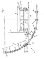
- Fig. 1 eine Seitenansicht einer Bogenstahlstranggießanlage mit Kühlkammer und Vorrichtung für einen kurzen Anfahrstrang,
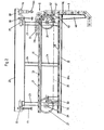
- Fig. 2 eine Seitenansicht der Aufnahme für einen kurzen Anfahrstrang in der Aufnahmephase,
- Fig. 3 einen Querschnitt durch die Aufnahme für mehrere Anfahrstränge,
- Fig. 4 eine Draufsicht auf die Aufnahme für mehrere Anfahrstränge,
- Fig. 5 eine Seitenansicht der Aufnahme entsprechend Fig. 2 in der Phase, in der der kurze Anfahrstrang auf der Ablageebene liegt und
- Fig. 6 eine Seitenansicht der Aufnahme entsprechend den Fig. 2 und 5 in der Phase, in der der kurze Anfahrstrang in die Einförderebene bewegt wird.
- 1 is a side view of a continuous sheet steel caster with cooling chamber and device for a short start-up strand,
- 2 is a side view of the recording for a short start-up line in the recording phase,
- 3 shows a cross section through the receptacle for several start-up lines,
- 4 is a plan view of the receptacle for several start-up lines,
- Fig. 5 is a side view of the recording corresponding to FIG. 2 in the phase in which the short start-up strand lies on the storage level and
- Fig. 6 is a side view of the receptacle corresponding to FIGS. 2 and 5 in the phase in which the short start-up line is moved into the feed plane.
In der Bogenstahlstranganlage 1 wird die Metallschmelze in eine Stranggießkokille 2 eingegossen, nachdem zuvor der relativ kurze Anfahrstrang 3 von unten in die Stranggießkokille 2 eingefahren worden ist und eine Abdichtung 4 am Rande des Gießquerschnitts eingefügt wurde. Das Einfahren des relativ kurzen Anfahrstranges 3 erfolgt aus einer Aufnahme 5, die über dem Treib-Richt-Aggregat 6 und neben einer Kühlkammer 7 in Stellung gebracht wird. Die Kühlkammer 7 weist für den Einfahrvorgang eine Klappe 8 auf, und bei geöffneter Klappe 8 wird der Anfahrstrang 3 über eine Führung 9 durch eine Öffnung 10 bis in den Wirkbereich von Treiberrollen 11 und von diesen zwischen Stützrollenpaare 12a des Rollengerüstes 12 mit dem Anfahrkopf 13 voraus in den Eingangsbereich der Stranggießkokille 2 geschoben. Bei Gießbeginn werden sodann die Treiberrollen 11 solange durch den Drehantrieb 14 (nur angedeutet) beaufschlagt, bis der Anfahrstrang 3 zusammen mit dem daran hängenden Gußstrang (nicht sichtbar) in den Wirkbereich des Treib-Richt-Aggregats 6 gelangt. Nachdem der Anfahrstrang 3 mit seinem rückwärtigen Ende 3a das letzte Antriebswalzenpaar 6a in Gießrichtung 15 passiert hat, wird er an einer Öse 3b an einem Fanghaken 16a einer Hubvorrichtung 16 hängend in die Aufnahme 5 transpottiert (Fig. 2).In the sheet steel extrusion plant 1, the molten metal is poured into a
Die Aufnahme 5 (Fig. 2 bis 6) ist auf einer quer zur Gießrichtung 15 verlaufenden Schienenbahn 17 in der Art einer Kranbahn verfahrbar.The receptacle 5 (FIGS. 2 to 6) can be moved on a
Die Aufnahme 5 weist ferner eine Einförderebene 18 und eine darüberliegende Ablageebene 19 auf.The
Der weitere Aufbau der Aufnahme 5, die kurze Rüstzeiten für den Anfahrstrang 3 gewährleistet und eine aufwendige Stahlkonstruktion zur Lagerung von längeren Anfahrsträngen vermeidet, Ist wie folgt gegliedert: Die Aufnahme 5 wird durch fest verbundene waagerechte Rahmenteile 20,21 und 22 sowie durch senkrechte Rahmenteile 23,24 und 25 gebildet. Hierbei weist der horizontale Rahmenteil 22 die Einförderebene 18 auf und der horizontale Rahmenteil 21 die Ablageebene 19. Die Ablageebene 19 trägt Rollenpaare 26. Die Einfördereebene 18 wird durch Rollen 26a gebildet. Auf der Einförderebene 18 abgestützt, jedoch beiden Ebenen durch Abstimmung des Durchmessers und der Umfangsanordnung zugeordnet, sind an den Enden der Aufnahme 5 jeweils Kettenräder 27 und 28 drehgelagert. Über ein Paar solcher Kettenräder verläuft eine Antriebskette 29, an der zumindest ein Mitnehmer 30 befestigt ist. Die Kette 29 bzw. das Kettenrad 27 Ist mittels des Getriebes 31 und eines über eine Kupplung 32 verbundenen Motors 33 angetrieben.The further structure of the
Für eine Mehrstranggießanlage sind im Abstand mehrerer paralleler Gießadern (Fig. 3) In den Fahrtrichtungen 34 der Aufnahme 5 jeweils Kettenräder 27, 28 und separate Getriebe 31 mit Motoren 33 vorgesehen. Jeder Gießader Ist auch jeweils eine Hubvorrichtung 16 zugeordnet.For a multi-strand casting system,
Die Aufnahme 5 ist mittels der Räderpaare 35 und 36 und des Fahrantriebs 37 verfahrbar (Fig. 3 und 4). Am Rahmenteil 20 Ist außerdem ein Vorsprung 38 für die Hubvorrichtung 16 gebildet. Der Einförderseite 39 gegenüber, am Ende 5a der Aufnahme 5, ist am Rahmenteil 22 eine vertikale Führungsschiene 40 vorgesehen. Das Transportmittel für den Anfahrstrang 3 lenkt den Anfahrstrang 3 in der in Fig. 2 gezeichneten Phase mittels der Weiche 41 in die Auflageebene 19 um, so daß das eine Ende 3a des Anfahrstranges 3 mit der Öse 3b in die Auflageebene 19 einläuft. Die Weiche 41 besteht aus der Zunge 42, die um die Achse 43 einer Rolle 26a schwenkbar gelagert ist. Der Anfahrstrang 3 wird bis In die Lage gemäß Fig. 5 hochgezogen, in der er auf der Auflageebene 19 liegt. Zum Transport in die Einförderebene 18 in Transportrichtung 44 wird die Weiche 41 umgestellt (Fig. 6), so daß der Motor 33 die Kette 29 mit dem Anfahrstrang 3 in die Einförderebene 18 transportiert. Der Anfahrstrang 3 gelangt auf diese Art mit dem Anfahrkopf 13 in Einförderrichtung 44 in die Führung 9 und in die Öffnung 10 und damit zwischen die Treiberrollen 11, wie eingangs beschrieben.The
Claims (5)
dadurch gekennzeichnet,
daß die Aufnahme (5) auf einer quer zur Gießrichtung (15) verlaufenden Schienenbahn (17) verfahrbar Ist und eine Einförderebene (18) und eine Ablageebene (19) aufweist, wobei Einförderebene (18) und Ablageebene (19) miteinander durch ein den Anfahrstrang (3) umlenkendes Transportmittel verbunden und in übereinander befindlichen Höhenlagen angeordnet sind.1. Device for a short start-up strand, which can be inserted from a receptacle approximately horizontally between driver rollers arranged in the arc shape of a sheet metal continuous casting installation through an opening in the roller stand or in the cooling chamber,
characterized,
that the receptacle (5) can be moved on a rail track (17) running transversely to the casting direction (15) and has an infeed plane (18) and a storage plane (19), the infeed plane (18) and the storage plane (19) being connected to one another by a start-up line (3) deflecting means of transport are connected and are arranged at high altitudes.
dadurch gekennzeichnet,
daß die Aufnahme (5) aus waagerechten Rahmenteilen (20,21,22) und senkrechten Rahmenteilen (23,24,25) besteht, wobei die Einförderebene (18) aus einem horizontalen Rahmenteil (22) und die Ablageebene (19) aus dem horizontalen Rahmenteil (21) mit jeweils angeordneten Rollenpaaren (26) besteht, wobei zwischen den Rollenpaaren (26) eine um Kettenräder (27,28) geführte Antriebskette (29) mit Mitnehmern (30) vorgesehen ist.2. Device according to claim 1,
characterized,
that the receptacle (5) consists of horizontal frame parts (20, 21, 22) and vertical frame parts (23, 24, 25), the infeed plane (18) from a horizontal frame part (22) and the storage plane (19) from the horizontal Frame part (21) with respectively arranged pairs of rollers (26), a drive chain (29) with drivers (30) guided around chain wheels (27, 28) being provided between the pairs of rollers (26).
dadurch gekennzeichnet,
daß in Fahrtrichtung (34) der Aufnahme (5) parallel nebeneinander im Abstand mehrerer paralleler Gießadern jeweils Rollenpaare (26), bzw. Rollen (26a), Kettenräder (27,28) und Antriebsketten (29) vorgesehen sind.3. Device according to claims 1 and 2,
characterized,
that pairs of rollers (26) or rollers (26a), sprockets (27, 28) and drive chains (29) are provided in parallel in the direction of travel (34) of the receptacle (5) next to one another at a distance from a plurality of parallel casting wires.
dadurch gekennzeichnet,
daß an dem der Einförderseite (39) gegenüberliegenden Ende (5a) der Aufnahme (5) jeweils eine Hubvorrichtung (16) über der.Ablageebene (19) und jeweils tangential zu einem Kettenrad (28) mit Kette (29) am Rahmenteil (22) der Einförderebene (18) eine vertikale Führungsschiene (40) vorgesehen sind.4. Device according to claims 1 to 3,
characterized,
that at the end (5a) of the receptacle (5) opposite the feed side (39) there is in each case a lifting device (16) above the storage plane (19) and in each case tangential to a sprocket (28) with chain (29) on the frame part (22) a vertical guide rail (40) is provided on the conveying plane (18).
dadurch gekennzeichnet,
daß dem den Anfahrstrang (3) umlenkenden Transportmittel zwischen der Ablageebene (19) und der Einförderebene (18) eine die Einförderebene (18) freigebende oder verschließende Weiche (41) zugeordnet ist.5. The device according to one or more of claims 1 to 4,
characterized,
that the transport means deflecting the start-up line (3) between the storage level (19) and the infeed level (18) is assigned a switch (41) which releases or closes the infeed level (18).
Priority Applications (1)
| Application Number | Priority Date | Filing Date | Title |
|---|---|---|---|
| AT86730104T ATE56641T1 (en) | 1985-07-10 | 1986-07-07 | DEVICE FOR A SHORT LAUNCH. |
Applications Claiming Priority (2)
| Application Number | Priority Date | Filing Date | Title |
|---|---|---|---|
| DE3524553 | 1985-07-10 | ||
| DE3524553A DE3524553C1 (en) | 1985-07-10 | 1985-07-10 | Device for a short start-up line |
Publications (3)
| Publication Number | Publication Date |
|---|---|
| EP0208649A2 true EP0208649A2 (en) | 1987-01-14 |
| EP0208649A3 EP0208649A3 (en) | 1989-03-01 |
| EP0208649B1 EP0208649B1 (en) | 1990-09-19 |
Family
ID=6275361
Family Applications (1)
| Application Number | Title | Priority Date | Filing Date |
|---|---|---|---|
| EP86730104A Expired - Lifetime EP0208649B1 (en) | 1985-07-10 | 1986-07-07 | Apparatus for a short dummy bar |
Country Status (4)
| Country | Link |
|---|---|
| EP (1) | EP0208649B1 (en) |
| JP (1) | JPS6264459A (en) |
| AT (1) | ATE56641T1 (en) |
| DE (1) | DE3524553C1 (en) |
Cited By (1)
| Publication number | Priority date | Publication date | Assignee | Title |
|---|---|---|---|---|
| CN103068503A (en) * | 2010-05-15 | 2013-04-24 | Sms西马格股份公司 | Method and apparatus for the continuous casting of a metal bar |
Families Citing this family (3)
| Publication number | Priority date | Publication date | Assignee | Title |
|---|---|---|---|---|
| JPH0529350U (en) * | 1991-04-17 | 1993-04-20 | 日本真空技術株式会社 | Fresh flower freshness container for appreciation |
| JP2558133Y2 (en) * | 1991-04-22 | 1997-12-17 | 環境エンジニアリング株式会社 | Flowering tree cultivation container |
| AT3790U1 (en) | 1999-09-06 | 2000-08-25 | Voest Alpine Ind Anlagen | DEVICE AND METHOD FOR RECORDING, MOVING AND INSERTING A START-UP STRAND |
Citations (4)
| Publication number | Priority date | Publication date | Assignee | Title |
|---|---|---|---|---|
| FR2074742A1 (en) * | 1970-01-23 | 1971-10-08 | Fives Lille Cail | |
| FR2334448A1 (en) * | 1975-12-11 | 1977-07-08 | Concast Ag | CONTINUOUS CASTING PLANT FOR STEEL |
| FR2342111A1 (en) * | 1976-02-26 | 1977-09-23 | Voest Ag | DEVICE FOR INTRODUCING A FLEXIBLE FLEXIBLE BAR FITTED WITH A STARTING HEAD IN A CONTINUOUS CASTING SYSTEM |
| FR2361958A1 (en) * | 1976-08-21 | 1978-03-17 | Demag Ag | TRANSPORT TROLLEY FOR THE START OF CASTING BAR OF A CONTINUOUS METAL CASTING PLANT |
Family Cites Families (1)
| Publication number | Priority date | Publication date | Assignee | Title |
|---|---|---|---|---|
| CH423107A (en) * | 1965-05-26 | 1966-10-31 | Concast Ag | Method for operating a continuous casting plant and device for carrying out this method |
-
1985
- 1985-07-10 DE DE3524553A patent/DE3524553C1/en not_active Expired
-
1986
- 1986-07-07 AT AT86730104T patent/ATE56641T1/en not_active IP Right Cessation
- 1986-07-07 EP EP86730104A patent/EP0208649B1/en not_active Expired - Lifetime
- 1986-07-10 JP JP61162892A patent/JPS6264459A/en active Granted
Patent Citations (4)
| Publication number | Priority date | Publication date | Assignee | Title |
|---|---|---|---|---|
| FR2074742A1 (en) * | 1970-01-23 | 1971-10-08 | Fives Lille Cail | |
| FR2334448A1 (en) * | 1975-12-11 | 1977-07-08 | Concast Ag | CONTINUOUS CASTING PLANT FOR STEEL |
| FR2342111A1 (en) * | 1976-02-26 | 1977-09-23 | Voest Ag | DEVICE FOR INTRODUCING A FLEXIBLE FLEXIBLE BAR FITTED WITH A STARTING HEAD IN A CONTINUOUS CASTING SYSTEM |
| FR2361958A1 (en) * | 1976-08-21 | 1978-03-17 | Demag Ag | TRANSPORT TROLLEY FOR THE START OF CASTING BAR OF A CONTINUOUS METAL CASTING PLANT |
Cited By (1)
| Publication number | Priority date | Publication date | Assignee | Title |
|---|---|---|---|---|
| CN103068503A (en) * | 2010-05-15 | 2013-04-24 | Sms西马格股份公司 | Method and apparatus for the continuous casting of a metal bar |
Also Published As
| Publication number | Publication date |
|---|---|
| DE3524553C1 (en) | 1986-07-31 |
| ATE56641T1 (en) | 1990-10-15 |
| JPS6264459A (en) | 1987-03-23 |
| EP0208649A3 (en) | 1989-03-01 |
| EP0208649B1 (en) | 1990-09-19 |
| JPH025503B2 (en) | 1990-02-02 |
Similar Documents
| Publication | Publication Date | Title |
|---|---|---|
| DE3331469A1 (en) | SYSTEM FOR AUTOMATIC POSITIONING AND WELDING OF VEHICLE BODIES | |
| DE4136266A1 (en) | DEVICE FOR STRINGING STRAND-SHAPED GOODS, IN PARTICULAR LARGER CROSS-SECTIONS WITH ALTERNATING PUNCHING DIRECTION | |
| DE1961378A1 (en) | Device for winding and / or unwinding cables | |
| EP0208649B1 (en) | Apparatus for a short dummy bar | |
| DE1815049B1 (en) | Device for introducing and discharging a starting strand of a continuous casting plant | |
| DE2420240C3 (en) | Device for transporting a die casting from a die casting machine into a trimming press | |
| DE3230833A1 (en) | DEVICE FOR PRINTING, PUNCHING OR CUTTING CARDBOARD UNITS | |
| EP0481323A1 (en) | Method for feeding a production machine with a precision centering and apparatus therefor | |
| DE69015461T2 (en) | Assembly line for maintenance and repair of vehicle bodies. | |
| DE2332888A1 (en) | CONTINUOUS CASTING PLANT | |
| DE3522553C1 (en) | ||
| DE2702894A1 (en) | DRIVE ROLLER FRAMEWORK FOR A MULTI-LINE CASTING PLANT | |
| DE1685830A1 (en) | Machine for making cables or ropes | |
| DE1920757A1 (en) | Billet guide for continuous casting plant - with curved discharge channel | |
| DE2637824C3 (en) | Transport trolley for the starting line of a continuous metal caster | |
| DE1239440B (en) | Device for changing the roller guide segments of continuous casting plants | |
| DE2635950A1 (en) | BURNER AND CUTTING DEVICE | |
| DE309241C (en) | ||
| DE2702134C2 (en) | Extraction device with downstream reel device for a cast strand in a horizontal continuous caster | |
| EP0688707A1 (en) | Device for transporting of vehicles through a car wash | |
| EP0140198A2 (en) | Assembly line for motor vehicles | |
| DE1481780A1 (en) | Wire rope conveyor system | |
| EP0017645A1 (en) | Installation for extracting and introducing a starter bar in a continuous casting plant | |
| DE2340844A1 (en) | Continuous casting appts mechanism - for handling and downwardly loading starter bars | |
| EP1197423B1 (en) | Lifting device |
Legal Events
| Date | Code | Title | Description |
|---|---|---|---|
| PUAI | Public reference made under article 153(3) epc to a published international application that has entered the european phase |
Free format text: ORIGINAL CODE: 0009012 |
|
| AK | Designated contracting states |
Kind code of ref document: A2 Designated state(s): AT CH GB IT LI |
|
| 17P | Request for examination filed |
Effective date: 19861217 |
|
| PUAL | Search report despatched |
Free format text: ORIGINAL CODE: 0009013 |
|
| AK | Designated contracting states |
Kind code of ref document: A3 Designated state(s): AT CH GB IT LI |
|
| 17Q | First examination report despatched |
Effective date: 19890918 |
|
| ITF | It: translation for a ep patent filed | ||
| GRAA | (expected) grant |
Free format text: ORIGINAL CODE: 0009210 |
|
| AK | Designated contracting states |
Kind code of ref document: B1 Designated state(s): AT CH GB IT LI |
|
| REF | Corresponds to: |
Ref document number: 56641 Country of ref document: AT Date of ref document: 19901015 Kind code of ref document: T |
|
| GBT | Gb: translation of ep patent filed (gb section 77(6)(a)/1977) | ||
| PLBE | No opposition filed within time limit |
Free format text: ORIGINAL CODE: 0009261 |
|
| STAA | Information on the status of an ep patent application or granted ep patent |
Free format text: STATUS: NO OPPOSITION FILED WITHIN TIME LIMIT |
|
| 26N | No opposition filed | ||
| PGFP | Annual fee paid to national office [announced via postgrant information from national office to epo] |
Ref country code: GB Payment date: 19920507 Year of fee payment: 7 |
|
| PGFP | Annual fee paid to national office [announced via postgrant information from national office to epo] |
Ref country code: CH Payment date: 19920616 Year of fee payment: 7 |
|
| PGFP | Annual fee paid to national office [announced via postgrant information from national office to epo] |
Ref country code: AT Payment date: 19920622 Year of fee payment: 7 |
|
| ITTA | It: last paid annual fee | ||
| PG25 | Lapsed in a contracting state [announced via postgrant information from national office to epo] |
Ref country code: GB Effective date: 19930707 Ref country code: AT Effective date: 19930707 |
|
| PG25 | Lapsed in a contracting state [announced via postgrant information from national office to epo] |
Ref country code: LI Effective date: 19930731 Ref country code: CH Effective date: 19930731 |
|
| GBPC | Gb: european patent ceased through non-payment of renewal fee |
Effective date: 19930707 |
|
| REG | Reference to a national code |
Ref country code: CH Ref legal event code: PL |
|
| PG25 | Lapsed in a contracting state [announced via postgrant information from national office to epo] |
Ref country code: IT Free format text: LAPSE BECAUSE OF NON-PAYMENT OF DUE FEES;WARNING: LAPSES OF ITALIAN PATENTS WITH EFFECTIVE DATE BEFORE 2007 MAY HAVE OCCURRED AT ANY TIME BEFORE 2007. THE CORRECT EFFECTIVE DATE MAY BE DIFFERENT FROM THE ONE RECORDED. Effective date: 20050707 |