EP0208232A1 - Dichtheitsprüfmaschine für Teile nach der sogenannten Ausscheidungsmethode - Google Patents
Dichtheitsprüfmaschine für Teile nach der sogenannten Ausscheidungsmethode Download PDFInfo
- Publication number
- EP0208232A1 EP0208232A1 EP86108931A EP86108931A EP0208232A1 EP 0208232 A1 EP0208232 A1 EP 0208232A1 EP 86108931 A EP86108931 A EP 86108931A EP 86108931 A EP86108931 A EP 86108931A EP 0208232 A1 EP0208232 A1 EP 0208232A1
- Authority
- EP
- European Patent Office
- Prior art keywords
- chamber
- piston
- horizontal
- ramp
- pivoting
- Prior art date
- Legal status (The legal status is an assumption and is not a legal conclusion. Google has not performed a legal analysis and makes no representation as to the accuracy of the status listed.)
- Granted
Links
Images


Classifications
-
- G—PHYSICS
- G01—MEASURING; TESTING
- G01M—TESTING STATIC OR DYNAMIC BALANCE OF MACHINES OR STRUCTURES; TESTING OF STRUCTURES OR APPARATUS, NOT OTHERWISE PROVIDED FOR
- G01M3/00—Investigating fluid-tightness of structures
- G01M3/02—Investigating fluid-tightness of structures by using fluid or vacuum
- G01M3/04—Investigating fluid-tightness of structures by using fluid or vacuum by detecting the presence of fluid at the leakage point
- G01M3/20—Investigating fluid-tightness of structures by using fluid or vacuum by detecting the presence of fluid at the leakage point using special tracer materials, e.g. dye, fluorescent material, radioactive material
- G01M3/22—Investigating fluid-tightness of structures by using fluid or vacuum by detecting the presence of fluid at the leakage point using special tracer materials, e.g. dye, fluorescent material, radioactive material for pipes, cables or tubes; for pipe joints or seals; for valves; for welds; for containers, e.g. radiators
- G01M3/226—Investigating fluid-tightness of structures by using fluid or vacuum by detecting the presence of fluid at the leakage point using special tracer materials, e.g. dye, fluorescent material, radioactive material for pipes, cables or tubes; for pipe joints or seals; for valves; for welds; for containers, e.g. radiators for containers, e.g. radiators
- G01M3/229—Investigating fluid-tightness of structures by using fluid or vacuum by detecting the presence of fluid at the leakage point using special tracer materials, e.g. dye, fluorescent material, radioactive material for pipes, cables or tubes; for pipe joints or seals; for valves; for welds; for containers, e.g. radiators for containers, e.g. radiators removably mounted in a test cell
-
- B—PERFORMING OPERATIONS; TRANSPORTING
- B07—SEPARATING SOLIDS FROM SOLIDS; SORTING
- B07C—POSTAL SORTING; SORTING INDIVIDUAL ARTICLES, OR BULK MATERIAL FIT TO BE SORTED PIECE-MEAL, e.g. BY PICKING
- B07C5/00—Sorting according to a characteristic or feature of the articles or material being sorted, e.g. by control effected by devices which detect or measure such characteristic or feature; Sorting by manually actuated devices, e.g. switches
- B07C5/34—Sorting according to other particular properties
-
- G—PHYSICS
- G01—MEASURING; TESTING
- G01M—TESTING STATIC OR DYNAMIC BALANCE OF MACHINES OR STRUCTURES; TESTING OF STRUCTURES OR APPARATUS, NOT OTHERWISE PROVIDED FOR
- G01M3/00—Investigating fluid-tightness of structures
- G01M3/02—Investigating fluid-tightness of structures by using fluid or vacuum
Definitions
- the present invention relates to a machine for checking the tightness of parts by the so-called penetrant method.
- a known method is to create a vacuum in the part to be checked and to put it in communication with a leak detector and then to spray the part externally with a tracer gas. If the room has cracks, the gas enters the room and is detected by the detector. However, the part to be checked may have no access orifice to evacuate it, this is the case for example of integrated electronic circuits.
- penetrant method which consists in placing the part to be checked under a bell containing helium under a pressure of a few atmospheres. Then, the part is put in the open air to ventilate it then again, it is placed under a bell connected to a vacuum pump and to a detector. The helium which may have penetrated into any cracks in the part is then detected.
- the invention therefore applies to the tightness control of such parts having no internal access hole and relates to a machine for carrying out the tightness test itself, that is to say that the machine receives parts previously pressurized in a tracer gas atmosphere then aerated.
- the subject of the invention is therefore a machine for checking the tightness of parts by the so-called penetrant method, characterized in that it comprises: a pivoting test chamber of which a first end is open and of which a second opposite end is closed and comprises a horizontal axis of rotation, a ramp for loading said parts, a docking member making it possible to achieve, on command, sealed communication between a leak detector and the open end of said chamber, an unloading ramp for two channels provided with orientation means towards one or the other channel and means for controlling the pivoting of said chamber in three possible orientations, the first at an angle 0 (above the horizontal aligning the chamber with the loading ramp, the second along the horizontal in alignment with said docking means and the third at an angle ⁇ below the horizontal in alignment with the unloading ramp, the angels ⁇ and ⁇ being sufficient to allow the movement of said part in the room by simple gravity.
- said docking member comprises a hollow movable piston connected by a flexible connection to said leak detector, said piston being able to slide inside a fixed cylinder, the cylinder and the piston cooperating with control means allowing the displacement in one direction and in the other of the movable piston in the fixed cylinder, the open end of said chamber and the end of the piston opposite to its connection with said detector comprising means ensuring sealing of the junction between the chamber and said movable piston when the piston is in the docking position against the open end of said chamber.
- the machine essentially comprises a pivoting chamber 1 comprising a first end 2 open and a second end 3 closed.
- the pivoting chamber comprises, near its closed end 3, a horizontal axis of rotation 4 allowing the chamber to pivot.
- the rotation of the chamber is controlled by a jack 5.
- Figure 3 shows the section of the chamber, an integrated electronic circuit 6 to be tested is contained therein.
- the machine further comprises a loading ramp 7, a docking member 8 and an unloading ramp 9 with two tracks of output 10 and 11 supplied by an orientation ramp 12 whose position is controlled by an articulated jack 13. These elements are linked to a frame 14.
- the pivoting chamber 1 can take three positions: the first at an angle ⁇ above the horizontal position, in alignment with the loading ramp 7, this position is fictitiously represented in FIG. 1 by the dashed line 15 and by the line in thin lines from the end of the pivoting chamber; a second horizontal position, which is that shown in Figures 1 and 2 and which places the chamber in alignment with the docking member 8; and a third position making an angle f3 downwards with respect to the horizontal position and aligning the pivoting chamber 1 with the unloading ramp 9.
- This latter position is also easily shown in FIG. 1 by the dashed line 15A and by the fine line drawing of the end of the pivoting chamber.
- the angles ⁇ and ⁇ are advantageously, but not necessarily, equal. In addition, they have a value large enough to allow sliding by simple gravity of the devices 6 to be tested.
- the loading ramp 7 is provided with an electro-optical device 16-17 for counting which makes it possible to count the passage of each circuit. These are stopped by a retractable stop 18 maneuvered by an electromagnet 19.
- a drive wheel 20 provided with a rubber pad allows at will to retain or free the circuits 21 arriving in the loading ramp 7.
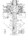
- FIG. 2 shows in enlarged view the docking member 8 which makes it possible to connect the pivoting chamber 1 in a leaktight manner, by its open end 2, with a leak detector, not shown, provided with pumping means and thus to realize the tightness test of the integrated circuit or circuits such as 6 located in the pivoting chamber.
- the docking member 8 is connected to the detector by a flexible link 22.
- the docking member 8 comprises a hollow piston 23 which is connected to said flexible connection 22 in a sealed manner by means of a clamp 24 tightening two end flanges 25 and 26 against an O-ring 27 whose l crushing is limited by a ring 28.
- the hollow piston 23 can slide inside a fixed cylinder 29, made in two parts 30 and 31 connected by screws such as 32, and fixed to the frame 14 by screws and nuts, such as 33 and 34.
- a seal 35 seals the assembly of the two parts 30 and 31.
- the bore of the cylinder 29 is open at its two ends so that the piston 23 completely passes through the cylinder, in addition, an annular chamber 36 is provided in this bore.
- Pneumatic lines 37 and 38 terminate at the two ends of this annular chamber 36 making it possible to actuate in one direction or the other according to the arrows 50 and 60, the hollow piston 23 which comprises a flange 39 housed in said chamber separating it, in a sealed manner by means of a seal 40, in two parts, the sealing of the external side of which is ensured respectively by seals 41 and 42 housed in grooves 43 and 44 of the cylinder 29.
- the left end of the hollow piston 23 is provided with a seal 45 which is applied, when one is in the test position, which is that shown in FIGS. 1 and 2, against a support flange 46 secured to the open end 2 of the pivoting chamber 1.
- the piston 23 of the docking member 8 is in the retracted position, that is to say pushed back in the direction of the arrow 60 by a pneumatic pressure sent into the pipe 37.
- the desired number of circuits to be tested is then allowed to pass through the pivoting chamber 1 by retracting the stop 18.
- the circuits which pass are then counted by the counting system 16-17.
- the pivoting chamber is then placed in a horizontal position in alignment with the docking member 8, then the pressure is sent through the pipe 38 in order to move the hollow piston 23 in the direction of the arrow 50 so as to form the sealed connection.
Landscapes
- Physics & Mathematics (AREA)
- General Physics & Mathematics (AREA)
- Examining Or Testing Airtightness (AREA)
- Investigating Materials By The Use Of Optical Means Adapted For Particular Applications (AREA)
- Electrical Discharge Machining, Electrochemical Machining, And Combined Machining (AREA)
- Automobile Manufacture Line, Endless Track Vehicle, Trailer (AREA)
- Medicines Containing Material From Animals Or Micro-Organisms (AREA)
- Saccharide Compounds (AREA)
- Separation By Low-Temperature Treatments (AREA)
- Encapsulation Of And Coatings For Semiconductor Or Solid State Devices (AREA)
Priority Applications (1)
| Application Number | Priority Date | Filing Date | Title |
|---|---|---|---|
| AT86108931T ATE44097T1 (de) | 1985-07-04 | 1986-07-01 | Dichtheitspruefmaschine fuer teile nach der sogenannten ausscheidungsmethode. |
Applications Claiming Priority (2)
| Application Number | Priority Date | Filing Date | Title |
|---|---|---|---|
| FR8510241A FR2584495B1 (fr) | 1985-07-04 | 1985-07-04 | Machine pour controler l'etancheite de pieces par la methode dite de ressuage. |
| FR8510241 | 1985-07-04 |
Publications (2)
| Publication Number | Publication Date |
|---|---|
| EP0208232A1 true EP0208232A1 (de) | 1987-01-14 |
| EP0208232B1 EP0208232B1 (de) | 1989-06-14 |
Family
ID=9320974
Family Applications (1)
| Application Number | Title | Priority Date | Filing Date |
|---|---|---|---|
| EP86108931A Expired EP0208232B1 (de) | 1985-07-04 | 1986-07-01 | Dichtheitsprüfmaschine für Teile nach der sogenannten Ausscheidungsmethode |
Country Status (8)
| Country | Link |
|---|---|
| US (1) | US4663963A (de) |
| EP (1) | EP0208232B1 (de) |
| JP (1) | JPS629259A (de) |
| AT (1) | ATE44097T1 (de) |
| DE (1) | DE3664002D1 (de) |
| FI (1) | FI82552C (de) |
| FR (1) | FR2584495B1 (de) |
| IN (1) | IN167893B (de) |
Families Citing this family (2)
| Publication number | Priority date | Publication date | Assignee | Title |
|---|---|---|---|---|
| GB2327766A (en) * | 1997-07-28 | 1999-02-03 | Geoffrey Poulson | Leak detection apparatus |
| US10031041B2 (en) * | 2016-06-17 | 2018-07-24 | Hewlett Packard Enterprise Development Lp | Rope leak sensor holder |
Citations (2)
| Publication number | Priority date | Publication date | Assignee | Title |
|---|---|---|---|---|
| US3126734A (en) * | 1964-03-31 | High speed high sensitivity leak detector | ||
| US4184362A (en) * | 1978-07-24 | 1980-01-22 | Abbott Laboratories | Bottle leak tester |
Family Cites Families (3)
| Publication number | Priority date | Publication date | Assignee | Title |
|---|---|---|---|---|
| US3486365A (en) * | 1967-11-16 | 1969-12-30 | Nat Res Corp | Leak detector and vacuum pumping station for high production rates |
| JPS57137835A (en) * | 1981-02-20 | 1982-08-25 | Hitachi Ltd | Leakage detector |
| US4608866A (en) * | 1985-03-13 | 1986-09-02 | Martin Marietta Corporation | Small component helium leak detector |
-
1985
- 1985-07-04 FR FR8510241A patent/FR2584495B1/fr not_active Expired
-
1986
- 1986-06-17 IN IN536/DEL/86A patent/IN167893B/en unknown
- 1986-06-27 US US06/879,748 patent/US4663963A/en not_active Expired - Fee Related
- 1986-06-30 FI FI862770A patent/FI82552C/fi not_active IP Right Cessation
- 1986-07-01 AT AT86108931T patent/ATE44097T1/de active
- 1986-07-01 EP EP86108931A patent/EP0208232B1/de not_active Expired
- 1986-07-01 DE DE8686108931T patent/DE3664002D1/de not_active Expired
- 1986-07-04 JP JP61157745A patent/JPS629259A/ja active Granted
Patent Citations (2)
| Publication number | Priority date | Publication date | Assignee | Title |
|---|---|---|---|---|
| US3126734A (en) * | 1964-03-31 | High speed high sensitivity leak detector | ||
| US4184362A (en) * | 1978-07-24 | 1980-01-22 | Abbott Laboratories | Bottle leak tester |
Non-Patent Citations (3)
| Title |
|---|
| PATENTS ABSTRACTS OF JAPAN, vol. 6, no. 237 (P-157)[1115], 25 novembre 1982; & JP-A-57 137 835 (HITACHI SEISAKUSHO K.K.) 25-08-1982 * |
| SOLID STATE TECHNOLOGY, vol. 26, no. 7, juillet 1983, pages 45,46, Port Washington, New York, US; "Automated leak tester" * |
| WESTERN ELECTRIC, TECHNICAL DIGEST, no. 35, juillet 1974, pages 19,20, New York, US; R.M. FILEK et al.: "Testing and sorting apparatus" * |
Also Published As
| Publication number | Publication date |
|---|---|
| EP0208232B1 (de) | 1989-06-14 |
| FI862770A7 (fi) | 1987-01-05 |
| FI82552B (fi) | 1990-11-30 |
| ATE44097T1 (de) | 1989-06-15 |
| DE3664002D1 (en) | 1989-07-20 |
| JPH0447254B2 (de) | 1992-08-03 |
| FI82552C (fi) | 1991-03-11 |
| JPS629259A (ja) | 1987-01-17 |
| US4663963A (en) | 1987-05-12 |
| FR2584495A1 (fr) | 1987-01-09 |
| FR2584495B1 (fr) | 1989-05-05 |
| FI862770A0 (fi) | 1986-06-30 |
| IN167893B (de) | 1991-01-05 |
Similar Documents
| Publication | Publication Date | Title |
|---|---|---|
| FR2491807A1 (fr) | Dispositif de prise de pieces realisant successivement un serrage et un blocage | |
| EP1123780A2 (de) | Ausrichtbare Vakuum-Greifervorrichtung für den Transport oder die Bearbeitung eines beliebig geformten Werkstückes | |
| FR2672834A1 (fr) | Organe de serrage et de prehension. | |
| FR2755481A1 (fr) | Dispositif de maintien en position et sous charge d'un verin hydraulique | |
| FR2612109A1 (fr) | Dispositif de changement d'outil de robot | |
| EP0014614B1 (de) | Demontierbare Vorrichtung für die Einfügung eines Gerätes zwischen zwei Rohren | |
| EP0208232B1 (de) | Dichtheitsprüfmaschine für Teile nach der sogenannten Ausscheidungsmethode | |
| US5181543A (en) | Tube testing connector | |
| EP0296442B1 (de) | Ventil für Vakuumbehälter | |
| FR2464395A1 (fr) | Appareil hydraulique a piston, notamment pour coupe d'ecrous, raccord hydraulique tournant et pompe hydraulique | |
| FR2731071A1 (fr) | Indicateur de pression differentielle | |
| FR2647872A1 (fr) | Joint hydraulique tournant a equilibrage hydrostatique | |
| EP0144337B1 (de) | Druckluftspareinrichtung | |
| FR2752609A1 (fr) | Vanne a boule a relachement de la pression residuelle | |
| EP0345112B1 (de) | Verankerungsvorrichtung für ein Bohrlochgerät mit ausstellbaren Gelenkarmen | |
| EP0490798B1 (de) | Kran, insbesondere für die Handhabung | |
| FR2470326A1 (fr) | Dispositif porte-orifice pour mesure de debit dans les canalisations sous pression | |
| FR2688307A1 (fr) | Procede de detection et de quantification globale de fuites sur au moins une jonction d'une capacite. | |
| EP1697088B1 (de) | Schnellklemmvorrichtung und steuerverfahren | |
| CA1310997C (fr) | Tete de prehension de produits plats | |
| FR2505699A1 (fr) | Mandrin interne utilise dans une operation d'assemblage bout a bout de deux troncons de tubes par soudage | |
| EP1072366A1 (de) | Fördereinrichtung | |
| FR2631675A1 (fr) | Vanne a soufflet | |
| FR2773887A1 (fr) | Articulation orientable pour dispositif de correction d'attenuation de transmission | |
| WO2021001624A1 (fr) | Outil de récupération d'un élément solide, notamment un matériau radioactif, comprenant une tête de capture et un godet |
Legal Events
| Date | Code | Title | Description |
|---|---|---|---|
| PUAI | Public reference made under article 153(3) epc to a published international application that has entered the european phase |
Free format text: ORIGINAL CODE: 0009012 |
|
| AK | Designated contracting states |
Kind code of ref document: A1 Designated state(s): AT BE CH DE FR GB IT LI LU NL SE |
|
| RAP1 | Party data changed (applicant data changed or rights of an application transferred) |
Owner name: ALCATEL CIT |
|
| 17P | Request for examination filed |
Effective date: 19870713 |
|
| 17Q | First examination report despatched |
Effective date: 19880914 |
|
| GRAA | (expected) grant |
Free format text: ORIGINAL CODE: 0009210 |
|
| AK | Designated contracting states |
Kind code of ref document: B1 Designated state(s): AT BE CH DE FR GB IT LI LU NL SE |
|
| REF | Corresponds to: |
Ref document number: 44097 Country of ref document: AT Date of ref document: 19890615 Kind code of ref document: T |
|
| REF | Corresponds to: |
Ref document number: 3664002 Country of ref document: DE Date of ref document: 19890720 |
|
| GBT | Gb: translation of ep patent filed (gb section 77(6)(a)/1977) | ||
| ITF | It: translation for a ep patent filed | ||
| PLBE | No opposition filed within time limit |
Free format text: ORIGINAL CODE: 0009261 |
|
| STAA | Information on the status of an ep patent application or granted ep patent |
Free format text: STATUS: NO OPPOSITION FILED WITHIN TIME LIMIT |
|
| 26N | No opposition filed | ||
| PGFP | Annual fee paid to national office [announced via postgrant information from national office to epo] |
Ref country code: SE Payment date: 19910521 Year of fee payment: 6 |
|
| PGFP | Annual fee paid to national office [announced via postgrant information from national office to epo] |
Ref country code: CH Payment date: 19910523 Year of fee payment: 6 |
|
| PGFP | Annual fee paid to national office [announced via postgrant information from national office to epo] |
Ref country code: FR Payment date: 19910530 Year of fee payment: 6 |
|
| PGFP | Annual fee paid to national office [announced via postgrant information from national office to epo] |
Ref country code: BE Payment date: 19910605 Year of fee payment: 6 |
|
| PGFP | Annual fee paid to national office [announced via postgrant information from national office to epo] |
Ref country code: LU Payment date: 19910607 Year of fee payment: 6 |
|
| PGFP | Annual fee paid to national office [announced via postgrant information from national office to epo] |
Ref country code: GB Payment date: 19910612 Year of fee payment: 6 Ref country code: DE Payment date: 19910612 Year of fee payment: 6 |
|
| ITTA | It: last paid annual fee | ||
| PGFP | Annual fee paid to national office [announced via postgrant information from national office to epo] |
Ref country code: NL Payment date: 19910731 Year of fee payment: 6 Ref country code: AT Payment date: 19910731 Year of fee payment: 6 |
|
| EPTA | Lu: last paid annual fee | ||
| PG25 | Lapsed in a contracting state [announced via postgrant information from national office to epo] |
Ref country code: LU Free format text: LAPSE BECAUSE OF NON-PAYMENT OF DUE FEES Effective date: 19920701 Ref country code: GB Effective date: 19920701 Ref country code: AT Effective date: 19920701 |
|
| PG25 | Lapsed in a contracting state [announced via postgrant information from national office to epo] |
Ref country code: SE Effective date: 19920702 |
|
| PG25 | Lapsed in a contracting state [announced via postgrant information from national office to epo] |
Ref country code: LI Effective date: 19920731 Ref country code: CH Effective date: 19920731 Ref country code: BE Effective date: 19920731 |
|
| BERE | Be: lapsed |
Owner name: ALCATEL CIT Effective date: 19920731 |
|
| PG25 | Lapsed in a contracting state [announced via postgrant information from national office to epo] |
Ref country code: NL Effective date: 19930201 |
|
| GBPC | Gb: european patent ceased through non-payment of renewal fee |
Effective date: 19920701 |
|
| NLV4 | Nl: lapsed or anulled due to non-payment of the annual fee | ||
| PG25 | Lapsed in a contracting state [announced via postgrant information from national office to epo] |
Ref country code: FR Effective date: 19930331 |
|
| REG | Reference to a national code |
Ref country code: CH Ref legal event code: PL |
|
| PG25 | Lapsed in a contracting state [announced via postgrant information from national office to epo] |
Ref country code: DE Effective date: 19930401 |
|
| REG | Reference to a national code |
Ref country code: FR Ref legal event code: ST |
|
| EUG | Se: european patent has lapsed |
Ref document number: 86108931.6 Effective date: 19930204 |
|
| PG25 | Lapsed in a contracting state [announced via postgrant information from national office to epo] |
Ref country code: IT Free format text: LAPSE BECAUSE OF NON-PAYMENT OF DUE FEES;WARNING: LAPSES OF ITALIAN PATENTS WITH EFFECTIVE DATE BEFORE 2007 MAY HAVE OCCURRED AT ANY TIME BEFORE 2007. THE CORRECT EFFECTIVE DATE MAY BE DIFFERENT FROM THE ONE RECORDED. Effective date: 20050701 |