EP0208001A1 - Device for bending sheets with trapezoidal corrugations - Google Patents
Device for bending sheets with trapezoidal corrugations Download PDFInfo
- Publication number
- EP0208001A1 EP0208001A1 EP85108110A EP85108110A EP0208001A1 EP 0208001 A1 EP0208001 A1 EP 0208001A1 EP 85108110 A EP85108110 A EP 85108110A EP 85108110 A EP85108110 A EP 85108110A EP 0208001 A1 EP0208001 A1 EP 0208001A1
- Authority
- EP
- European Patent Office
- Prior art keywords
- trapezoidal
- sheets
- gears
- rollers
- lower flange
- Prior art date
- Legal status (The legal status is an assumption and is not a legal conclusion. Google has not performed a legal analysis and makes no representation as to the accuracy of the status listed.)
- Withdrawn
Links
Images
Classifications
-
- B—PERFORMING OPERATIONS; TRANSPORTING
- B21—MECHANICAL METAL-WORKING WITHOUT ESSENTIALLY REMOVING MATERIAL; PUNCHING METAL
- B21D—WORKING OR PROCESSING OF SHEET METAL OR METAL TUBES, RODS OR PROFILES WITHOUT ESSENTIALLY REMOVING MATERIAL; PUNCHING METAL
- B21D11/00—Bending not restricted to forms of material mentioned in only one of groups B21D5/00, B21D7/00, B21D9/00; Bending not provided for in groups B21D5/00 - B21D9/00; Twisting
- B21D11/08—Bending by altering the thickness of part of the cross-section of the work
-
- B—PERFORMING OPERATIONS; TRANSPORTING
- B21—MECHANICAL METAL-WORKING WITHOUT ESSENTIALLY REMOVING MATERIAL; PUNCHING METAL
- B21D—WORKING OR PROCESSING OF SHEET METAL OR METAL TUBES, RODS OR PROFILES WITHOUT ESSENTIALLY REMOVING MATERIAL; PUNCHING METAL
- B21D11/00—Bending not restricted to forms of material mentioned in only one of groups B21D5/00, B21D7/00, B21D9/00; Bending not provided for in groups B21D5/00 - B21D9/00; Twisting
- B21D11/20—Bending sheet metal, not otherwise provided for
- B21D11/206—Curving corrugated sheets
-
- B—PERFORMING OPERATIONS; TRANSPORTING
- B21—MECHANICAL METAL-WORKING WITHOUT ESSENTIALLY REMOVING MATERIAL; PUNCHING METAL
- B21D—WORKING OR PROCESSING OF SHEET METAL OR METAL TUBES, RODS OR PROFILES WITHOUT ESSENTIALLY REMOVING MATERIAL; PUNCHING METAL
- B21D13/00—Corrugating sheet metal, rods or profiles; Bending sheet metal, rods or profiles into wave form
- B21D13/04—Corrugating sheet metal, rods or profiles; Bending sheet metal, rods or profiles into wave form by rolling
Definitions
- the invention relates to a device for the arcuate shaping of trapezoidal sheets by pressing depressions into the lower or upper flange of the sheets.
- Trapezoidal sheets are metal sheets that are stiffened by folding in a trapezoidal shape in such a way that they oppose deformation at right angles to the folds due to the short trapezoidal legs lying approximately in this direction.
- Flat sheets of this type are thus outstandingly suitable for producing containers and interim structures and the like, that is to say constructions which are roughly cuboid.
- trapezoidal sheets which are deformed in an arc shape are also required, for example for the top closure or for the construction of barrel roofs, for the manufacture of so-called "Nissen huts" or for other special purposes.
- edge-shaped deformation that is to say the introduction of the notches and the buckling of the trapezoidal sheets
- the trapezoidal sheets must be carried out successively on a correspondingly shaped press with special tools, and is therefore relatively expensive and lengthy.
- the trapezoidal sheets as is almost the norm nowadays, are coated for surface protection or for beautification, generally plastic-coated, there is a risk with this type of deformation that the surface layer will flake off or at least crack, so that later corrosive effects this layer is detached.
- the invention has set itself the task of deforming such trapezoidal sheets in the longitudinal direction of the folds so that there is actually a circular arc section in the side view and also so that wrinkling and the risk of tearing a coating is largely avoided.
- This is achieved according to the invention by a device which is characterized by a number corresponding to the number of upper and lower chords at least at a distance from the sheet thickness intermeshing, independently synchronously driven pairs of gears, each taking up the belt between them and shaping them into waves.
- the particular advantage of the invention lies not only in the fact that the deformation actually takes place in an arc and that the unsightly and damaging creasing is avoided, but also that the deformation can now be carried out quickly and inexpensively in a continuous process.
- rollers running on the trapezoidal sheet are arranged on a common axis in the feed direction after the gear pair, the height of which can be adjusted above the rolling line of the meshing gear pairs.
- the rollers can also be combined to form a roller that extends over the entire width of the trapezoidal sheet to be formed.
- a plurality of such rolls or rollers can also be provided in succession in the feed direction.
- the fact that the center distance of the meshing gears, and thus the depth of the corrugation, is adjustable.
- the width of the gear wheel engaging on the underside of the lower flange should be equal to the width of the widest lower flange.
- the gear wheels engaging on the underside of the lower flange are combined to form a toothed roller.
- a pair of feed rollers which accommodate the trapezoidal sheet between them is arranged in the feed direction. Also to facilitate the introduction of the trapezoidal sheets into the device according to the invention, as well as to maintain the shape of the trapezoidal sheet at the beginning and at the end of the outer gear pairs on the outer legs of the trapezoidal shaped sheets rolling form holding rollers are arranged.
- the tooth shapes of the meshing pairs of gears are the same, so that there is a uniform corrugation. From an aesthetic point of view, however, it can also be considered advantageous to design tooth shapes of the intermeshing gearwheels differently.
- the gearwheels acting on the top of the lower flange expediently have a cross section corresponding approximately to the trapezoidal shape of the trapezoidal sheet.
- shaping rollers can also be provided, which therefore not only deform the lower flange in a wave shape, but overall have the trapezoidal shape of the trapezoidal sheet to be shaped.
- Trapezoidal sheets 1 are trapezoidally shaped in such a way that a lower flange 2 and an upper flange 3 result with webs 4 formed between them by the short trapezoid legs. Such webs 4 have a very high degree of rigidity with regard to deformation perpendicular to the folds.
- Arch-shaped trapezoidal sheets are desired, as are shown, for example, in FIG. 2, the lower chord 2 being on the inside of the arcuate deformation and the upper chord 3 being on the outside of this deformed trapezoidal sheet.
- the trapezoidal sheet with its lower flange 2 is inserted between a pair of gear wheels 5, 6, each with synchronously driven gear wheels 5, 6, so that the lower flange 2, as can be seen from Fig.
Abstract
Description
Die Erfindung betrifft eine Vorrichtung zum bogenförmigen Verformen von Trapezblechen durch Eindrücken von Vertiefungen in den Unter- oder Obergurt der Bleche.The invention relates to a device for the arcuate shaping of trapezoidal sheets by pressing depressions into the lower or upper flange of the sheets.
"Trapezbleche" sind Blechtafeln, die durch Abkanten in Trapezform so versteift sind, daß sie einem Verformen senkrecht zu den Abkantungen durch die etwa in dieser Richtung liegenden kurzen Trapezschenkel einen sehr großen Widerstand entgegensetzen. Derartige ebene Bleche eignen sich damit hervorragend zum Herstellen von Containern und Interimsbauten und dergleichen, also Konstruktionen, die etwa quaderförmig sind. Gefordert werden jedoch auch Trapezbleche, die bogenförmig verformt sind, beispielsweise zum oberseitigen Abschluß beziehungsweise zum Erstellen von Tonnendächern, zum Herstellen von sogenannten "Nissenhütten" oder auch für sonstige Spezialzwecke."Trapezoidal sheets" are metal sheets that are stiffened by folding in a trapezoidal shape in such a way that they oppose deformation at right angles to the folds due to the short trapezoidal legs lying approximately in this direction. Flat sheets of this type are thus outstandingly suitable for producing containers and interim structures and the like, that is to say constructions which are roughly cuboid. However, trapezoidal sheets which are deformed in an arc shape are also required, for example for the top closure or for the construction of barrel roofs, for the manufacture of so-called "Nissen huts" or for other special purposes.
Um das Verformen solcher Trapezbleche trotz der ihnen innewohnenden Steifigkeit zu ermöglichen, gehört es zum Stand der Technik, in bestimmten Abständen in den, im allgemeinen eine geringere Breite aufweisenden Untergurt derartiger Trapezbleche Kerben einzudrücken und die Bleche sodann an dieser Stelle zu knicken. Durch die Krafteinwirkung bei diesem Knickvorgang beulen hierbei die verbleibenden kurzen Trapezschenkel aus beziehungsweise bilden sichtbare Falten. Diese Falten sehen nicht nur unschön aus, sondern mindern auch sehr stark die Festigkeit derart behandelter Trapezbleche. Unschön sehen diese Bleche auch in der Seitenansicht aus, da nicht eine bogenförmige, sondern eine kantige Verformung erfolgt, die Seitenansicht also einen Polygonzug zeigt. Schließlich wird auch noch als Nachteil empfunden, daß die kantenförmige Verformung, also das Einbringen der Kerben und das Knicken der Trapezbleche, sukzessive auf einer entsprechend geformten Presse mit Spezialwerkzeugen erfolgen muß, daher verhältnismäßig teuer und langwierig ist. Sind darüberhinaus die Trapezbleche, wie dies heutzutage schon fast die Regel ist, zum Oberflächenschutz beziehungsweise zur Verschönerung beschichtet, im allgemeinen kunststoffbeschichtet, so besteht bei dieser Art der Verformung die Gefahr, daß die Oberflächenschicht abplatzt oder doch zumindest einreißt, so daß durch spätere korrosive Einwirkungen ein Ablösen dieser Schicht erfolgt.In order to enable the deformation of such trapezoidal sheets in spite of their inherent rigidity, it is part of the prior art to indent notches at certain intervals in the generally lower width of the lower chord of such trapezoidal sheets and then to bend the sheets at this point. The remaining short trapezoidal legs bulge out or form visible folds due to the action of force during this buckling process. These folds not only look ugly, they also reduce the strength of trapezoidal sheets treated in this way. These sheets also look unattractive in the side view, since not an arcuate but an angular deformation occurs, so the side view shows a polygon. Finally, it is also perceived as a disadvantage that the edge-shaped deformation, that is to say the introduction of the notches and the buckling of the trapezoidal sheets, must be carried out successively on a correspondingly shaped press with special tools, and is therefore relatively expensive and lengthy. If, moreover, the trapezoidal sheets, as is almost the norm nowadays, are coated for surface protection or for beautification, generally plastic-coated, there is a risk with this type of deformation that the surface layer will flake off or at least crack, so that later corrosive effects this layer is detached.
Die Erfindung hat sich die Aufgabe gestellt, derartige Trapezbleche in Längsrichtung der Abkantungen bogenförmig zu verformen, so, daß sich tatsächlich in der Seitenansicht ein rund laufender Bogenabschnitt ergibt und auch so, daß eine Faltenbildung und die Gefahr des Einreißens einer Beschichtung weitgehend vermieden wird. Erreicht wird dies nach der Erfindung durch eine Vorrichtung, die gekennzeichnet ist durch eine der Unter- oder Obergurtzahl entsprechende Anzahl von mindestens im Abstand der Blechdicke ineinanderkämmenden, unabhängig voneinander synchron angetriebenen Zahnradpaaren, die jeweils den Gurt zwischen sich aufnehmen und wellenförmig formen.The invention has set itself the task of deforming such trapezoidal sheets in the longitudinal direction of the folds so that there is actually a circular arc section in the side view and also so that wrinkling and the risk of tearing a coating is largely avoided. This is achieved according to the invention by a device which is characterized by a number corresponding to the number of upper and lower chords at least at a distance from the sheet thickness intermeshing, independently synchronously driven pairs of gears, each taking up the belt between them and shaping them into waves.
Nicht mehr also wie bisher werden in größeren Abständen Kerben in den Gurt des Trapezbleches eingedrückt, die die oben gekennzeichneten Nachteile mit sich bringen, sondern es wird lediglich der Gurt wellenfärmig verformt und damit gekürzt, so daß sich das Trapezblech insgesamt, unter verhältnismäßig geringer Stauchung der durch die kurzen Trapezschenkel gebildeten Stege, bogenförmig verformt. Der Grad dieser bogenförmigen Verformung wird hierbei gegeben zum einen durch die Tiefe der Wellung und zum anderen durch den Abstand der einzelnen Wellen voneinander beziehungsweise insgesamt durch die Kürzung von Unter- oder Obergurt, relativ zueinander.No longer, as before, notches are pressed into the belt of the trapezoidal sheet at greater intervals, which bring the disadvantages identified above, but only the belt is deformed in a wave shape and thus shortened, so that the trapezoidal sheet as a whole, with relatively little compression webs formed by the short trapezoidal legs, arch-shaped. The degree of this arcuate deformation is given on the one hand by the depth of the corrugation and on the other hand by the spacing of the individual corrugations from one another or overall by the shortening of the lower or upper flange relative to one another.
Der besondere Vorteil der Erfindung liegt jedoch nicht nur darin, daß die Verformung tatsächlich bogenmäßig erfolgt und daß die unschöne und zu Beschädigungen führende Faltenbildung vermieden wird, sondern auch, daß die Verformung nunmehr in einem kontinuierlichen Verfahren zügig und preiswert durchgeführt werden kann.The particular advantage of the invention lies not only in the fact that the deformation actually takes place in an arc and that the unsightly and damaging creasing is avoided, but also that the deformation can now be carried out quickly and inexpensively in a continuous process.
Um die Trapezbleche sicher in die vorbestimmte Bogenform zu verformen, werden nach der Erfindung in Vorschubrichtung nach dem Zahnradpaar auf einer gemeinsamen Achse laufende, am Trapezblech abrollende Rollen angeordnet, deren Höhenlage über der Wälzlinie der ineinanderkämmenden Zahnradpaare einstellbar ist. Die Rollen können hierbei auch zu einer, über die gesamte Breite des zu formenden Trapezbleches reichenden Walze zusammengefaßt sein. Auch können eine Mehrzahl derartiger Rollen beziehungsweise Walzen in Vorschubrichtung nacheinander vorgesehen werden. Durch diese Rollen wird das, die Zahnradpaare verlassende Trapezblech, unter geringfügiger Stauchung der durch die kurzen Trapezschenkel gebildeten Stege in die gewünschte Bogenform gedrückt. Durch diese Maßnahme werden Spannungen, die sich beim Einformen der Wellung ergeben haben, eliminiert beziehungsweise wird dafür gesorgt, daß das verformte Trapezblech tatsächlich in dieser Form stehen bleibt.In order to deform the trapezoidal sheets securely into the predetermined arch shape, according to the invention, rollers running on the trapezoidal sheet are arranged on a common axis in the feed direction after the gear pair, the height of which can be adjusted above the rolling line of the meshing gear pairs. The rollers can also be combined to form a roller that extends over the entire width of the trapezoidal sheet to be formed. A plurality of such rolls or rollers can also be provided in succession in the feed direction. Through these rollers, the trapezoidal sheet leaving the gearwheel pairs becomes slightly compressed by the short ones Trapezoid legs formed webs pressed into the desired arc shape. This measure eliminates tensions which have arisen during the shaping of the corrugation or ensures that the deformed trapezoidal sheet actually remains in this shape.
Hierzu kann einem weiteren Erfindungsmerkmal nach auch beitragen, daß der Achsabstand der ineinanderkämmenden Zahnräder, und damit die Tiefe der Wellung, einstellbar ist.According to a further feature of the invention, the fact that the center distance of the meshing gears, and thus the depth of the corrugation, is adjustable.
Die Breite des an der Unterseite des Untergurts angreifenden Zahnrads soll gleich der Breite des breitestens Untergurtes sein. Möglich ist jedoch auch, daß die an der Unterseite des Untergurts angreifenden Zahnräder zu einer Zahnwalze zusammengefaßt werden.The width of the gear wheel engaging on the underside of the lower flange should be equal to the width of the widest lower flange. However, it is also possible that the gear wheels engaging on the underside of the lower flange are combined to form a toothed roller.
Um kontinuierlich auf der erfindungsgemäßen Vorrichtung Trapezbleche verformen zu können und um außerdem das Einschieben der Trapezbleche in die Vorrichtung zu erleichtern, wird in Vorschubrichtung vor dem Zahnradpaar ein das Trapezblech zwischen sich aufnehmendes Vorschub-Walzenpaar angeordnet. Ebenfalls zum erleichterten Einführen der Trapezbleche in die Vorrichtung nach der Erfindung, wie auch zur Beibehaltung der Form des Trapezbleches am Anfang und am Ende werden beidseits der äußeren Zahnradpaare auf den äußeren Schenkeln der trapezförmig geformten Bleche abrollende Formhalterollen angeordnet.In order to be able to continuously deform trapezoidal sheets on the device according to the invention and also to facilitate the insertion of the trapezoidal sheets into the device, a pair of feed rollers which accommodate the trapezoidal sheet between them is arranged in the feed direction. Also to facilitate the introduction of the trapezoidal sheets into the device according to the invention, as well as to maintain the shape of the trapezoidal sheet at the beginning and at the end of the outer gear pairs on the outer legs of the trapezoidal shaped sheets rolling form holding rollers are arranged.
Im allgemeinen sind die Zahnformen der ineinanderkämmenden Zahnradpaare gleich, so daß sich eine gleichmäßige Wellung ergibt. Insbesondere aus ästhetischen Gesichtspunkten kann es jedoch auch als vorteilhaft angesehen werden, Zahnformen der ineinanderkämmenden Zahnräder unterschiedlich auszubilden.In general, the tooth shapes of the meshing pairs of gears are the same, so that there is a uniform corrugation. From an aesthetic point of view, however, it can also be considered advantageous to design tooth shapes of the intermeshing gearwheels differently.
Optimale Ergebnisse bei der Wellung werden dann erzielt, wenn die Zahnköpfe der Zahnräder flankenseitig mit einem etwa der Zahnkopfdicke entsprechenden Radius und zusätzlich auch noch die an der Oberseite des Gurts angreifenden Zahnräder auch seitlich verrundet sind. Schließlich ist auch noch festzuhalten, daß, zum Vermeiden einer Faltenbildung bei extrem starker Krümmung der Trapezbleche, zweckmäßigerweise die an der Oberseite des Untergurts angreifenden Zahnräder einen etwa der Trapezform des Trapezbleches entsprechenden Querschnitt aufweisen. In einem derartigen Falle, also bei extremer Krümmung der Trapezbleche, können auch Formwalzen vorgesehen werden, die also nicht nur den Untergurt wellenförmig verformen, sondern insgesamt die Trapezform des zu formenden Trapezbleches aufweisen.Optimal results in the corrugation are achieved if the tooth tips of the gear wheels are rounded on the flank side with a radius approximately corresponding to the tooth tip thickness and additionally the gear wheels acting on the top of the belt are also rounded on the side. Finally, it should also be noted that, in order to avoid wrinkling when the trapezoidal sheets are extremely curved, the gearwheels acting on the top of the lower flange expediently have a cross section corresponding approximately to the trapezoidal shape of the trapezoidal sheet. In such a case, that is, with extreme curvature of the trapezoidal sheets, shaping rollers can also be provided, which therefore not only deform the lower flange in a wave shape, but overall have the trapezoidal shape of the trapezoidal sheet to be shaped.
Auf der Zeichnung ist die Erfindung schematisch dargestellt, und zwar zeigen:
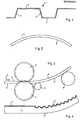
- Fig. 1 ein Trapezblech in Stirnansicht,
- Fig. 2 ein gebogenes Trapezblech,
- Fig. 3 die Vorrichtung nach der Erfindung und
- Fig. 4 den Längsschnitt eines teilweise gebogenen Trapezbleches.
- 1 is a trapezoidal sheet in front view,
- 2 is a curved trapezoidal sheet,
- Fig. 3 shows the device according to the invention and
- Fig. 4 shows the longitudinal section of a partially curved trapezoidal sheet.
Trapezbleche 1 sind trapezförmig so verformt, daß sich ein Untergurt 2 und ein Obergurt 3 ergibt mit dazwischenliegenden, durch die kurzen Trapezschenkel gebildeten Stege 4. Derartige Trapezbleche weisen durch die Stege 4 eine sehr große Steifigkeit hinsichtlich einer Verformung senkrecht zu den Abkantungen auf. Gewünscht werden bogenförmig verformte Trapezbleche, wie sie beispielsweise in Fig. 2 dargestellt sind, wobei der Untergurt 2 an der Innenseite der bogenförmigen Verformung und der Obergurt 3 an der Außenseite dieses verformten Trapezbleches liegt. Um dies zu erreichen wird das Trapezblech mit seinem Untergurt 2 zwischen ein Zahnradpaar 5, 6 mit jeweils synchron angetriebenen Zahnrädern 5, 6 eingeschoben, so daß der Untergurt 2, wie aus Fig. 4 ersichtlich, wellenförmig verformt wird. Durch diese wellenförmge Verformung wird der Untergurt 2 relativ zum Obergurt 3 gekürzt, so daß sich das Trapezblech insgesamt, unter geringfügiger Stauchung des Stegs 4, bogenmäßig verformt. Diese Verformung wird unterstützt beziehungsweise die durch die Wellung hervorgerufene Spannung im Trapezblech eliminiert durch eine das Trapezblech in die gewünschte Bogenform drückende Rolle 7, die nach den Zahnradpaaren 5, 6 angeordnet ist. Eine weitere Rolle 8 kann zum Ablaufen des gebogenen Trapezbleches, aber auch noch zur geringfügigen Verformung dienen.
Claims (15)
gekennzeichnet
durch eine der Unter- oder Obergurtzahl entsprechende Anzahl von mindestens im Abstand der Blechdicke ineinanderkämmenden, unabhängig voneinander synchron angetriebenen Zahnradpaaren (5, 6), die jeweils den Gurt (2) zwischen sich aufnehmen und wellenförmig formen.1. Device for the arcuate shaping of trapezoidal sheets by pressing depressions into the lower or upper chord of the sheets,
featured
by means of a number corresponding to the number of lower and upper chords of gear pairs (5, 6) which mesh with one another at least at a distance from the sheet thickness and are synchronously driven independently of one another and which each take up the chord (2) between them and form a wave shape.
dadurch gekennzeichnet,
daß je Untergurt (2) in Vorschubrichtunq (9) nach den Zahnradpaaren (5, 6) auf einer gemeinsamen Achse laufende, am Trapezblech (1) abrollende Rollen (7) angeordnet sind, deren Höhenlage relativ zur Wälzlinie der ineinanderkämmenden Zahnradpaare (5, 6) einstellbar ist.2. Device according to claim 1,
characterized,
that each lower chord (2) in the feed direction (9) after the gear pairs (5, 6) on a common axis running, on the trapezoidal sheet (1) rolling rollers (7) are arranged, the height of which mesh with each other relative to the rolling line the gear pairs (5, 6) is adjustable.
dadurch gekennzeichnet,
daß die Rollen (7) zu einer über die gesamte Breite des zu formenden Trapezbleches (1) reichenden Walze zusammengefaßt sind.3. Device according to claim 2,
characterized,
that the rollers (7) are combined to form a roller that extends over the entire width of the trapezoidal sheet (1) to be formed.
dadurch gekennzeichnet,
daß eine Mehrzahl derartiger Rollen (7) (Walzen) in Vorschubrichtung (9) nacheinander vorgesehen sind.4. Apparatus according to claim 2 or 3,
characterized,
that a plurality of such rollers (7) (rollers) are provided in the feed direction (9) one after the other.
dadurch gekennzeichnet,
daß der Achsabstand der ineinanderkämmenden Zahnräder (5, 6) einstellbar ist.5. The device according to claim 1,
characterized,
that the center distance of the meshing gears (5, 6) is adjustable.
dadurch gekennzeichnet,
daß die Breite des an der Unterseite des Untergurts (2) angreifenden Zahnrads (5) gleich der Breite des breitestes Untergurts (2) ist.6. The device according to claim 1,
characterized,
that the width of the gear (5) engaging on the underside of the lower flange (2) is equal to the width of the widest lower flange (2).
dadurch gekennzeichnet,
daß die an der Unterseite des Untergurts (2) angreifenden Zahnräder (5) zu einer Zahnwalze zusammengefaßt sind.7. The device according to claim 1,
characterized,
that the gears (5) engaging on the underside of the lower flange (2) are combined to form a toothed roller.
dadurch gekennzeichnet,
daß in Vorschubrichtung (9) vor den Zahnradpaaren (5, 6) ein das Trapezblech (1) zwischen sich aufnehmendes Vorschub-Walzenpaar angeordnet ist.8. The device according to claim 1
characterized,
that in the feed direction (9) in front of the gear pairs (5, 6) a trapezoidal sheet (1) is arranged between the feed roller pair.
dadurch gekennzeichnet,
daß beidseits der äußeren Zahnradpaare (5, 6) auf den äußeren Stegen (4) der trapezförmig geformten Bleche abrollende Formhalterollen angeordnet sind.9. The device according to claim 1,
characterized,
that on both sides of the outer pairs of gears (5, 6) on the outer webs (4) of the trapezoidally shaped sheets are arranged form-holding rollers.
dadurch gekennzeichnet,
daß die Zahnform der ineinanderkämmenden Zahnräder (5, 6) gleich ist.10. The device according to claim 1
characterized,
that the tooth shape of the meshing gears (5, 6) is the same.
dadurch gekennzeichnet,
daß die Zahnform der ineinanderkämmenden Zahnräder (5, 6) ungleich ist.11. The device according to claim 1,
characterized,
that the tooth shape of the meshing gears (5, 6) is not the same.
dadurch gekennzeichnet,
daß die Zahnköpfe der Zahnräder (5, 6) flankenseitig mit einem etwa der Zahnkopfdicke entsprechenden Radius verrundet sind.12. The device according to claim 1,
characterized,
that the tooth heads of the gears (5, 6) are rounded on the flank side with a radius approximately corresponding to the tooth head thickness.
dadurch gekennzeichnet,
daß die an der Obereite des Untergurts (2) angreifenden Zahnräder (6) auch seitlich verrundet sind.13. The apparatus according to claim 12,
characterized,
that the gears (6) engaging on the upper side of the lower flange (2) are also rounded on the side.
dadurch gekennzeichnet,
daß die an der Oberseite des Untergurts (2) angreifenden Zahnräder (6) einen etwa der Trapezform des Trapezbleches (1) entsprechenden Querschnitt aufweisen.14. The device according to one or more of the preceding claims,
characterized,
that the gears (6) engaging on the upper side of the lower flange (2) have a cross section corresponding approximately to the trapezoidal shape of the trapezoidal sheet (1).
dadurch gekennzeichnet,
daß die Trapezform des zu verformenden Trapezbleches (1) aufweisende Formwalzen mit entsprechenden, auf den Untergurt (2) einwirkenden Zahnradpaaren (5, 6) eingesetzt sind.15. The device according to one or more of the preceding claims,
characterized,
that the trapezoidal shape of the trapezoidal sheet to be deformed (1) has forming rollers with corresponding gear pairs (5, 6) acting on the lower flange (2).
Priority Applications (1)
| Application Number | Priority Date | Filing Date | Title |
|---|---|---|---|
| EP85108110A EP0208001A1 (en) | 1985-06-29 | 1985-06-29 | Device for bending sheets with trapezoidal corrugations |
Applications Claiming Priority (1)
| Application Number | Priority Date | Filing Date | Title |
|---|---|---|---|
| EP85108110A EP0208001A1 (en) | 1985-06-29 | 1985-06-29 | Device for bending sheets with trapezoidal corrugations |
Publications (1)
| Publication Number | Publication Date |
|---|---|
| EP0208001A1 true EP0208001A1 (en) | 1987-01-14 |
Family
ID=8193596
Family Applications (1)
| Application Number | Title | Priority Date | Filing Date |
|---|---|---|---|
| EP85108110A Withdrawn EP0208001A1 (en) | 1985-06-29 | 1985-06-29 | Device for bending sheets with trapezoidal corrugations |
Country Status (1)
| Country | Link |
|---|---|
| EP (1) | EP0208001A1 (en) |
Cited By (2)
| Publication number | Priority date | Publication date | Assignee | Title |
|---|---|---|---|---|
| EP0545100A1 (en) * | 1991-11-13 | 1993-06-09 | VAW Aluminium AG | Device for bending sheets with trapezoidal corrugations |
| CN104226760A (en) * | 2014-09-24 | 2014-12-24 | 浙江伟联科技有限公司 | Crumpling bending roll machine |
Citations (9)
| Publication number | Priority date | Publication date | Assignee | Title |
|---|---|---|---|---|
| DE87873C (en) * | ||||
| US1352813A (en) * | 1918-08-13 | 1920-09-14 | Kennicott | Machine for forming metal |
| US2775284A (en) * | 1953-01-21 | 1956-12-25 | Inland Steel Products Company | Machine for making arched panel sheets |
| US3394573A (en) * | 1966-02-01 | 1968-07-30 | Bodnar Ernest Robert | Process for continual stretch forming |
| DE1552031A1 (en) * | 1966-04-20 | 1969-12-18 | Mannesmann Ag | Process for bending trapezoidal sheets and machine for carrying out the process |
| US3842647A (en) * | 1972-02-14 | 1974-10-22 | G Knudson | Method and apparatus for making building panels |
| WO1982002914A1 (en) * | 1981-02-23 | 1982-09-02 | Gary Art Knudson | Wide panel,panel assembly,and panel forming apparatus |
| JPS57193239A (en) * | 1981-05-26 | 1982-11-27 | Sanko Metal Ind Corp Ltd | Molding method of building plate |
| JPS58116934A (en) * | 1981-12-30 | 1983-07-12 | Sanko Metal Ind Corp Ltd | Covering metallic material having partial curved part and its formation |
-
1985
- 1985-06-29 EP EP85108110A patent/EP0208001A1/en not_active Withdrawn
Patent Citations (9)
| Publication number | Priority date | Publication date | Assignee | Title |
|---|---|---|---|---|
| DE87873C (en) * | ||||
| US1352813A (en) * | 1918-08-13 | 1920-09-14 | Kennicott | Machine for forming metal |
| US2775284A (en) * | 1953-01-21 | 1956-12-25 | Inland Steel Products Company | Machine for making arched panel sheets |
| US3394573A (en) * | 1966-02-01 | 1968-07-30 | Bodnar Ernest Robert | Process for continual stretch forming |
| DE1552031A1 (en) * | 1966-04-20 | 1969-12-18 | Mannesmann Ag | Process for bending trapezoidal sheets and machine for carrying out the process |
| US3842647A (en) * | 1972-02-14 | 1974-10-22 | G Knudson | Method and apparatus for making building panels |
| WO1982002914A1 (en) * | 1981-02-23 | 1982-09-02 | Gary Art Knudson | Wide panel,panel assembly,and panel forming apparatus |
| JPS57193239A (en) * | 1981-05-26 | 1982-11-27 | Sanko Metal Ind Corp Ltd | Molding method of building plate |
| JPS58116934A (en) * | 1981-12-30 | 1983-07-12 | Sanko Metal Ind Corp Ltd | Covering metallic material having partial curved part and its formation |
Cited By (2)
| Publication number | Priority date | Publication date | Assignee | Title |
|---|---|---|---|---|
| EP0545100A1 (en) * | 1991-11-13 | 1993-06-09 | VAW Aluminium AG | Device for bending sheets with trapezoidal corrugations |
| CN104226760A (en) * | 2014-09-24 | 2014-12-24 | 浙江伟联科技有限公司 | Crumpling bending roll machine |
Similar Documents
| Publication | Publication Date | Title |
|---|---|---|
| EP2085163B1 (en) | Cold rolling process for the production of a profile | |
| DE4140729C2 (en) | Method and device for producing heat exchanger elements | |
| US3529461A (en) | Roll forming method and machine | |
| WO1997035705A1 (en) | Process for producing an embossed structure in thin material webs | |
| EP2108467B1 (en) | Method for producing highly dimensionally accurate half shells | |
| DE2803365C3 (en) | Method and device for the production of helical transverse ribs on a pipe by rolling | |
| DE19856236A1 (en) | Straightening structured sheet material containing bulges, uses rollers to bend or stretch material | |
| DE2529466B2 (en) | METHOD AND DEVICE FOR MANUFACTURING LATERAL SEAM WELDED PIPES OF VARIOUS DIAMETERS | |
| EP0208001A1 (en) | Device for bending sheets with trapezoidal corrugations | |
| DE4226402C2 (en) | Process for producing long thick-walled pipes by bending from a metal plate and device for carrying out the process | |
| DE8518952U1 (en) | Device for bending trapezoidal sheets | |
| DE2809365A1 (en) | Manufacture of corrugated sheet with deep corrugations - uses chains with special teeth to bunch corrugations and increase depth | |
| DE60120947T2 (en) | METHOD AND DEVICE FOR BENDING TABLE STRIPS WITH TWO OPPOSITE FLANGES | |
| DE4311228C2 (en) | Process for bending the edge strips of a flat sheet to be formed into a slotted tube | |
| DE2341857B1 (en) | Tool arrangement for making pipe arches | |
| DE69815790T2 (en) | Method and device for forming a side wall on a base plate | |
| EP0545100B1 (en) | Device for bending sheets with trapezoidal corrugations | |
| DE2721610B1 (en) | Press for pre-bending sheet metal blanks in the production of large pipes | |
| DE710902C (en) | Process for the production of pipes and profiles of all kinds | |
| DE19906553B4 (en) | Device for marginal profiling of sheets or metal strips | |
| WO2010118759A2 (en) | Bending press for sheet panels | |
| DE81789C (en) | ||
| DE498705C (en) | Method and device for the production of corrugated sheets | |
| DE1750877C (en) | Device for the production of plain bearing half-shells | |
| AT398047B (en) | METHOD FOR CHANGING THE SECTION OF AN EXTRUDED PROFILE |
Legal Events
| Date | Code | Title | Description |
|---|---|---|---|
| PUAI | Public reference made under article 153(3) epc to a published international application that has entered the european phase |
Free format text: ORIGINAL CODE: 0009012 |
|
| AK | Designated contracting states |
Kind code of ref document: A1 Designated state(s): AT BE CH DE FR GB IT LI NL SE |
|
| STAA | Information on the status of an ep patent application or granted ep patent |
Free format text: STATUS: THE APPLICATION IS DEEMED TO BE WITHDRAWN |
|
| 18D | Application deemed to be withdrawn |
Effective date: 19870715 |
|
| RIN1 | Information on inventor provided before grant (corrected) |
Inventor name: ZEISER, ERWIN Inventor name: ZEISER, PETER, DIPL.-ING. |