EP0207584A2 - Anordnung für Luftsackaufblasvorrichtung mit fernbetätigtem Sensor und Verbindungseinrichtung dazu - Google Patents
Anordnung für Luftsackaufblasvorrichtung mit fernbetätigtem Sensor und Verbindungseinrichtung dazu Download PDFInfo
- Publication number
- EP0207584A2 EP0207584A2 EP86302116A EP86302116A EP0207584A2 EP 0207584 A2 EP0207584 A2 EP 0207584A2 EP 86302116 A EP86302116 A EP 86302116A EP 86302116 A EP86302116 A EP 86302116A EP 0207584 A2 EP0207584 A2 EP 0207584A2
- Authority
- EP
- European Patent Office
- Prior art keywords
- inflator
- shaft
- hole
- fitting
- ring
- Prior art date
- Legal status (The legal status is an assumption and is not a legal conclusion. Google has not performed a legal analysis and makes no representation as to the accuracy of the status listed.)
- Granted
Links
Images
Classifications
-
- B—PERFORMING OPERATIONS; TRANSPORTING
- B60—VEHICLES IN GENERAL
- B60R—VEHICLES, VEHICLE FITTINGS, OR VEHICLE PARTS, NOT OTHERWISE PROVIDED FOR
- B60R21/00—Arrangements or fittings on vehicles for protecting or preventing injuries to occupants or pedestrians in case of accidents or other traffic risks
- B60R21/02—Occupant safety arrangements or fittings, e.g. crash pads
- B60R21/16—Inflatable occupant restraints or confinements designed to inflate upon impact or impending impact, e.g. air bags
- B60R21/20—Arrangements for storing inflatable members in their non-use or deflated condition; Arrangement or mounting of air bag modules or components
- B60R21/203—Arrangements for storing inflatable members in their non-use or deflated condition; Arrangement or mounting of air bag modules or components in steering wheels or steering columns
-
- B—PERFORMING OPERATIONS; TRANSPORTING
- B60—VEHICLES IN GENERAL
- B60R—VEHICLES, VEHICLE FITTINGS, OR VEHICLE PARTS, NOT OTHERWISE PROVIDED FOR
- B60R21/00—Arrangements or fittings on vehicles for protecting or preventing injuries to occupants or pedestrians in case of accidents or other traffic risks
- B60R21/02—Occupant safety arrangements or fittings, e.g. crash pads
- B60R21/16—Inflatable occupant restraints or confinements designed to inflate upon impact or impending impact, e.g. air bags
- B60R21/33—Arrangements for non-electric triggering of inflation
-
- F—MECHANICAL ENGINEERING; LIGHTING; HEATING; WEAPONS; BLASTING
- F16—ENGINEERING ELEMENTS AND UNITS; GENERAL MEASURES FOR PRODUCING AND MAINTAINING EFFECTIVE FUNCTIONING OF MACHINES OR INSTALLATIONS; THERMAL INSULATION IN GENERAL
- F16L—PIPES; JOINTS OR FITTINGS FOR PIPES; SUPPORTS FOR PIPES, CABLES OR PROTECTIVE TUBING; MEANS FOR THERMAL INSULATION IN GENERAL
- F16L27/00—Adjustable joints; Joints allowing movement
- F16L27/08—Adjustable joints; Joints allowing movement allowing adjustment or movement only about the axis of one pipe
- F16L27/087—Joints with radial fluid passages
-
- B—PERFORMING OPERATIONS; TRANSPORTING
- B60—VEHICLES IN GENERAL
- B60R—VEHICLES, VEHICLE FITTINGS, OR VEHICLE PARTS, NOT OTHERWISE PROVIDED FOR
- B60R21/00—Arrangements or fittings on vehicles for protecting or preventing injuries to occupants or pedestrians in case of accidents or other traffic risks
- B60R21/02—Occupant safety arrangements or fittings, e.g. crash pads
- B60R21/16—Inflatable occupant restraints or confinements designed to inflate upon impact or impending impact, e.g. air bags
- B60R21/33—Arrangements for non-electric triggering of inflation
- B60R2021/335—Connections between collision detecting means and inflators using pyrothechnic transmission lines
Definitions
- This invention relates to vehicle safety apparatus, and more particularly to a steering wheel mounted air bag safety system that is connected with apparatus mounted in another relatively stationary part of the vehicle.
- the gas generator or inflator of an air bag safety system for protecting the driver of a vehicle is advantageously mounted on the steering wheel.
- a major problem with steering wheel mounted inflator systems is the interface to the inflator to ignite it.
- Such a mounting requires that the connection for igniting the inflator must include a connector or coupling assembly which provides for relative motion between the steering wheel and the steering column while maintaining an ignitive connection between the inflator and a collision responsive sensor that usually is located in another and remote part of the vehicle.
- Space in the steering column is limited and the steering wheel is turned a great many times during the operation of the vehicle.
- the coupling assembly at the interface must, therefore, be both compact and reliable in operation. It must assure reliable operation during the life of the vehicle in which it is installed, which may be ten (10) years or longer.
- the coupling comprises a flexible printed circuit strip that is loosely coiled around the steering shaft with one end thereof electri cally connected to the shaft. The other end of the strip is electrically connected to the steering column. Slack in the strip is taken up or decreased by rotation of the steering wheel in one direction and re-established or increased by rotation of the steering wheel in the opposite direction.
- the coupling assembly provided in US-A-3,876,222 comprises a bearing having an inner race and an outer race with an electrically conductive lubricant hermetically sealed therein.
- the inner race and the outer race are secured to the steering shaft and steering column, respectively, each through an individually associated insulator.
- a first electrical cord leading to the inflator and a second electrical cord leading to a power source are connected to the inner race and outer race, respectively.
- electrical circuity is disadvantageous in a number of respects when employed in vehicle safety apparatus. This is for the reason that it may cause false or unwanted operation due to extraneous electrical currents or electromagnetic radiation, or operation, when required, may not occur due to failure of the electrical power source or shorting out of the circuitry. Electrical circuits also tend to become unreliable in operation over long periods of time as a result of wires becoming brittle and breaking. With circuits involving slip rings and brushes, there is difficulty, also, in maintaining circuit continuity, particularly in cold and freezing weather during which ice film formations or contact corrosion tend to break circuit continuity.
- Pyrotechnic inflator activating systems have certain advantages over electrical systems. These advantages include the following:
- a pyrotechnic system disclosed in U. S. Patent No. 3,552,796 issued to R. M. Kemmerer et al. on January 5, 1971, utilizes a mechanical sensor which fires a percussion primer upon the occurrence of a collision and a detonating fuse assembly for transmitting the percussive shock wave to a steering wheel mounted inflator.
- a coupling assembly is provided comprising a loop or ring of detonating fuse which is mounted on the steering wheel and extends from the inflator to an area of the steering wheel immediately adjacent to and concentric with the steering column.
- An object of the present invention is to provide for use in an vehicle safety apparatus comprising a steering wheel mounted inflator and a system for actuating the inflator responsively to the occurrence of a collision, as sensed by a remotely located and relatively stationary sensor, a new and improved assembly for coupling an ignitive reaction or detonating shock wave to the inflator from the sensor.
- Another object of the invention is to provide such an improved coupling assembly that may be readily and safely installed, at relatively low cost, on existing vehicles.
- a further object of the invention is to provide such an improved assembly that may readily be substituted for use with inflators designed for electrical actuation and intended to incorporate a squib therein for initiating the inflator operation.
- Still another object of the invention is to utilize a through bulkhead initiator of the inflator through a slip joint which holds the ignitive reaction transfer/booster stationary and allows the inflator to turn with the steering wheel.
- a pyrotechnic coupling assembly comprising an annular slip joint or ring which affords communication between a relatively stationary pyrotechnic transmission line from a remotely located collision responsive sensor and a pyrotechnic transmission line provided in the upper end of the cylindrical steering shaft, internally thereof.
- the last mentioned transmission line communicates with the inflator of an air bag safety system mounted on the steering wheel.
- the sensor may be placed at the base of the steering column, on the steering box, for example, or any other location for best sensing.
- the pyrotechnic coupling assembly includes a pyrotechnic transmission line that has one end connected to the inflator for initiating, that is, igniting it.
- the connection of the transmission line to the inflator is by means of a fitting.
- the transmission line extends from the inflator internally of and axially along an upper portion of the steering shaft through a first hole formed therein.
- the first hole has a first end and a second end with the first end even with the upper end of the shaft.
- the first hole is an axially extending hole and communicates at the second end thereof, internally of the shaft, with one end of a second hole.
- the second hole is a radial hole in the shaft that provides communication between the second end of the first hole and the outer cylindrical surface of the shaft.
- the slip ring is positioned in surrounding relationship with the shaft, having an inner cylindrical surface that mates with the cylindrical surface of the shaft, and is disposed in rotative sliding relationship therewith.
- Formed in the inner cylindrical surface of the slip ring is an internal annular groove or radial plenum which communicates with the radial hole in the steering shaft and thereby with the transmission line in the first or axially extending hole in the shaft.
- the radial plenum also communicates with a pyrotechnic transmission line leading from the sensor through a hole that extends radially from the radial plenum to the outer periphery of the ring.
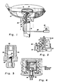
- Fig. 1 of the drawings the invention is illustrated in conjunction with a vehicle such as an automobile (not shown) having a steering wheel 10 that is mounted on a cylindr ical steering column 12 and is arranged for the rotation of a cylindrical steering shaft 14 for steering the automobile.
- An inflatable air bag 16 and a pyrotechnically actuated inflator or gas generator 18 are mounted in the hub portion of the steering wheel 10 with the inflator 18 being attached to the air bag 16 for the inflation thereof.
- a sensor 20 responsive to the onset of a collision and positioned for example at the base of the steering column on the steering box, is connected to the inflator 18 by pyrotechnic transmission lines 22 and 24 which are coupled together by a transmission line coupling device 26.
- Sensor 20 may include a percussion primer and mechanical firing pin means including an inertial mass for firing the primer under predetermined conditions of deceleration of the vehicle.
- the collision reponsive sensor 20 may be of a type that produces an electrical signal upon the onset of a collision and a blasting cap or squib may be provided on the steering box at the base of the steering column 12 for initiating an ignitive reaction in the transmission line 22 and of the pyrotechnic system.
- the transmission lines 22 and 24 may be of the type described in U.S. Patent No. 3,590,739 issued to Per-Anders Persson on July 6, 1971 for "Fuse.” Transmission lines of this type are sold commercially under the trademark "TLX” by Explosive Technology, a Subsidiary of OEA, Inc., Fairfield, California. This type of transmission line comprises a hollow tube having a reactive substance coating the inner surface thereof.
- the coating is operative to support and propagate a gaseous percussion wave throughout the length of the tube.
- the hollow pyrotechnic transmission lines may be of the type sold commercially by Explosive Technology under the Cord Designation "PP-23-T" and having an external diameter of 3.05 mm. and an internal diameter of 0.055 mm.
- Transmission line 22 extends from sensor 20 to a slip joint or ring 28 that is mounted on the steering shaft 14 of the vehicle between the steering shaft 14 and the steering column 12. Ring 28 is disposed in fixed relation with steering column 12 and in sliding relation with respect to steering shaft 14. Line 22 is connected to the slip ring 22 by a fitting 30 which is threadedly received in hole 31 in the slip ring 28.
- the slip ring 28 is supported on shaft 14 for relative rotation therewith between a shoulder 32 on shaft 14 and a hub 34 of the steering wheel 10. Hub 34 is attached to the upper end of shaft 14 in suitable manner by a bolt 36.
- the slip ring 28 has an inner surface that engages the surface of shaft 14 and has a radial plenum 38 that extends circumferentially of the ring and communicates with the end transmission line 22 through the fitting 30.
- a radial hole 29 having a diameter approximating that of the transmission line 22 provides communication between hole 31 and the radial plenum 38.
- Transmission line 22 terminates at the inner end of fitting 30 adjacent the outer end of radial hole 29.
- No reactive coating or other substance is provided, nor required, on the inner surface of the radial plenum 38 for transmitting an ignitive reaction from transmission line 22 to transmission line 24.
- an O-ring 40 is provided on one side of the radial plenum 38 and an O-ring 42 is provided on the other side thereof.
- Transmission line 24 is positioned in hole 44 that extends internally of and axially along a portion of the length of the steering shaft 14 from an upper or front end thereof.
- a radial hole 46 in shaft 14 at the inner or second end of hole 44 provides communication between the inner end of transmission line 24 and the radial plenum 38 formed by ring 28.
- the transmission line 24 is connected by a fitting 48 to the inflator 18, which fitting is threadedly received for ignitive reaction communication with an igniter chamber 47 therein, as best shown in Fig. 4.
- Fitting 48 is also threadedly received in the upper end of the steering shaft 14.
- Container 49 Positioned within igniter chamber 47 is a rupturable closed aluminum container 49 containing igniting material 56.
- Container 49 may be hermetically sealed against moisture and has a recess or cavity 53 formed in the bottom thereof which receives the end of fitting 48.
- fitting 48 may incorporate a check value 50 comprising a ball 52 that is adapted to engage in sealing manner a valve seat 54 to close the valve upon a rise in pressure within the inflator 18, as normally occurs upon the ignition thereof.
- a breakwire 55 may be provided on the exit end of fitting 48, that adjacent inflator 18, to provide an indication of whether or not ignition of the sensor 20 and the transmission lines 22 and 24 has occurred.
- the breakwire 55 may be provided on the upper end of the steering shaft 14, as seen in Fig. 1. While the breakwire 55 is intact, an installer of the system is assured that the pyrotechnic system has not been fired.
- a break in the breakwire 55 serves as a visual indication that such firing has occurred and that, therefore, the transmission system is no longer operative and requires replacement.
- the breakwire 55 may be connected, if desired, in a suitable electrical circuit including a lamp (not shown) mounted on the instrument panel of the vehicle to provide a visual indication to the operator as to the state of readiness of the pyrotechnic system to function.
- a pyrotechnic air bag system incorporating the invention is installed in an automobile as described with reference to Fig. 1.
- An impact of predetermined magnitude will cause the percussion primer in sensor 20 to fire to produce an ignitive reaction or detonating shock wave which is propagated through the pyrotechnic transmission line 22 to the coupling device 26.
- the shock wave enters the latter, finds the radial hole 46 in the steering shaft 14 that leads to the lower end of the pyrotechnic transmission line 24 and causes an ignitive reaction in the latter.
- This ignitive reaction occurs irrespective of the relative positions of the radial hole 46 and the fitting 30 that connects the transmission line 22 to the coupling device 26 and transmits the ignitive reaction to the igniter of the inflator 18.
- the air bag is rapidly inflated by tahe inflator 18.
- the invention may be used with inflators of known type including those fabricated using steel for the casing and other housing structural components.
- inflators typically, are initiated by the detonation of an electrically activated blasting cap or squib, as disclosed, for example, in the aforementioned Pruneski patent or in U. S. Patent No. 4,296,084 issued to Gary V. Adams, et al. on October 20, 1981 for METHOD OF AND APPARATUS FOR GAS GENERATION.
- the necessary modification for enabling such use may be made by removing the blasting cap or squib and the electrical circuity therefor and substituting therefor a fitting 48 with a check valve 50 therein, as illustrated in Fig. 4, and a pyrotechnic transfer line including a sensor 20, transmission lines 24 and 22, a coupling device 26, and a mechanical sensor 20.
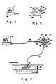
- a flange mount 56 that may advantageously be used with the sensor 20 of Fig. 1 for mounting the sensor at the base of the vehicle steering column or at another appropriate location.
- the flange mount 56 includes fastening holes 58 at each of the four corners thereof for bolting the mount 56 to the vehicle.
- a fitting 60 in one side of the flange mount 56 communicates internally thereof with a transfer pyrotechnic tube 62 that extends upwardly from the upper surface of the mount 56.
- the transfer tube 62 similarly to the pyrotechnic transmission lines 22 and 24 may include a reactive substance coating the inner surface thereof that is operative to support a gaseous percussion wave throughout the length thereof.
- the transfer tube 62 When a sensor 20 is coupled to the flange mount, the transfer tube 62 extends into the interior of the sensor. Upon actuation of the sensor 20 responsively to the onset of a collision, the transfer tube 62 is operative to transmit the percussion wave through the flange mount 56 and fitting 60 to a pyrotechnic transmission line for example, the line 22, as seen as Fig. 1.
- the upper surface 64 of flange mount 56 includes a keying slot 66 for faciliating the proper placement of the sensor 20 on it to effect the desired coupling to the transfer tube 62, a mating keying protection (not shown) being provided on the bottom surface of the associated sensor 20.
- arming pin 68 For preventing actuation of the sensor 20, when not mounted on the flange mount 56, as during shipping or when in storage, there desirably is provided on arming pin 68 from the bottom thereof.
- This arming pin 68 when projecting outwardly, as seen in Fig. 6, provides an interlock that prevents movement of the inertial mass to fire the percussion primer therein.
- the interlock is automatically released when the sensor is placed on the mounting flange 56 and bolted thereto and to the vehicle, such placement serving to push the arming pin 66 into the sensor thereby to effect the interlock release.
- Fig. 7 there is illustrated a modification of the invention utilizing a junction box 70 that is connected by a transmission line 86 to a mechanical sensor 88 that may be identical to the sensor 20 of Figs. 1 and 6 which is mounted on a flange mount 56 as illustrated in Fig. 5.
- the junction box 70 is provided for initiating a plurality of pyrotechnic transmission lines responsively to the actuation of a common, that is, the same sensor.
- the junction box 70 comprises a square metal block 72 having four tapped holes 74, 76, 78 and 80 therein with the holes all being in the same plane, one in each of the four sides of the block 72, and merging into a common opening 82 at the center of block 72.
- a common opening 82 at the center of block 72.
- An individually associated fitting for connecting a pyrotechnic transmission line is threadedly received in each of the holes 74, 76, 78 and 80.
- a fitting 84 received in hole 74 is connected by a transmission line 86 to a mechanical sensor 88.
- Another transmission line 90 connected at one end by a fitting 92 to hole 76 in the junction box 70, may be connected at its other end to a pyrotechnic transmission line leading to a wheel mounted inflator (not shown) which may be similar to the inflator 18 of Fig. 1.
- Such a connection would include a coupling device 26, a transmission line 24 in an axial hole 44 in the upper portion of the steering shaft, and a fitting 48 with a check valve 50 therein, as shown in Fig. 1.
- Still another one of the transmission lines, indicated at 94 and connected at one end by a fitting 96 to be tapped hole 78 in the junction box 70, may be connected at its other end directly to an inflator 98 that may be suitably positioned on the passenger side of an vehicle for protecting passengers therein.
- the connection at the other end of the transmission line 94 to the inflator 98 includes a fitting 100 having a check valve therein and which may be identical to the previously described fitting 48 with the check valve 50 and including a breakwire 55. Since there is no relative movement required between the inflator 98, which may be fixedly mounted on the vehicle dashboard, and the junction box 70, a coupling device, such as the coupling device 26 of Fig. 1, is not required for the passenger inflator 98.
- a fitting 102 in tapped hole 80 in junction box 70 may be used to initiate another pyrotechnic transmission line 104. If this fitting 102 and line 104 are not required, a suitable plug may be used to seal the hole 80.
- an improvement in vehicle safety apparatus comprising a pyrotechnically actuated inflator and remote sensor with through bulkhead inflator initiation.
- the invention has particular utility for steering wheel mounted inflators. It incorporates a simple and unique reliable assembly involving a minimum number of components for coupling at the interface to the inflator an ignitive reaction to ignite the inflator.
- the cost to install the system as an option on initial installation or after market is greatly reduced compared to the prior art systems.
- the system is safe to install since there is no electrical blasting cap or squib to be fired inadvertantly.
- Modifications required to existing inflators utilizing squib initiation, including light weight aluminum inflators, are very simple, as described hereinbefore.
- the weight added to the steering wheel and steering column is kept to a minimum.
- a breakwire on the end of the fitting that connects the pyrotechnic system to the inflator provides a ready means to monitor the state of readiness of the pyrotechnic system to function in the event of a collision of the vehicle of impact sufficient to actuate the collision responsive sensor.
Landscapes
- Engineering & Computer Science (AREA)
- Mechanical Engineering (AREA)
- General Engineering & Computer Science (AREA)
- Air Bags (AREA)
- Load-Engaging Elements For Cranes (AREA)
- Sampling And Sample Adjustment (AREA)
- Supplying Of Containers To The Packaging Station (AREA)
- Massaging Devices (AREA)
Priority Applications (1)
| Application Number | Priority Date | Filing Date | Title |
|---|---|---|---|
| AT86302116T ATE67454T1 (de) | 1985-07-02 | 1986-03-21 | Anordnung fuer luftsackaufblasvorrichtung mit fernbetaetigtem sensor und verbindungseinrichtung dazu. |
Applications Claiming Priority (2)
| Application Number | Priority Date | Filing Date | Title |
|---|---|---|---|
| US06/751,345 US4699400A (en) | 1985-07-02 | 1985-07-02 | Inflator and remote sensor with through bulkhead initiator |
| US751345 | 2000-12-28 |
Publications (3)
| Publication Number | Publication Date |
|---|---|
| EP0207584A2 true EP0207584A2 (de) | 1987-01-07 |
| EP0207584A3 EP0207584A3 (en) | 1988-05-11 |
| EP0207584B1 EP0207584B1 (de) | 1991-09-18 |
Family
ID=25021582
Family Applications (1)
| Application Number | Title | Priority Date | Filing Date |
|---|---|---|---|
| EP86302116A Expired EP0207584B1 (de) | 1985-07-02 | 1986-03-21 | Anordnung für Luftsackaufblasvorrichtung mit fernbetätigtem Sensor und Verbindungseinrichtung dazu |
Country Status (5)
| Country | Link |
|---|---|
| US (1) | US4699400A (de) |
| EP (1) | EP0207584B1 (de) |
| JP (1) | JPH0717179B2 (de) |
| AT (1) | ATE67454T1 (de) |
| DE (1) | DE3681514D1 (de) |
Cited By (3)
| Publication number | Priority date | Publication date | Assignee | Title |
|---|---|---|---|---|
| WO1992019476A1 (en) * | 1991-05-08 | 1992-11-12 | Autoliv Development Ab | A vehicle impact sensor arrangement |
| GB2263514B (en) * | 1992-01-27 | 1995-02-08 | Survival Eng Inc | Swivel valve |
| US5454590A (en) * | 1991-05-08 | 1995-10-03 | Autoliv Development Ab | Vehicle impact sensor arrangement |
Families Citing this family (23)
| Publication number | Priority date | Publication date | Assignee | Title |
|---|---|---|---|---|
| US5007661A (en) * | 1989-05-16 | 1991-04-16 | Trw Vehicle Safety Systems Inc. | Safety apparatus |
| US5145209A (en) * | 1990-02-13 | 1992-09-08 | Trw Vehicle Safety Systems Inc. | Seat belt pretensioner |
| US5032696A (en) * | 1990-07-23 | 1991-07-16 | Buell Industries, Inc. | Crash sensor switch |
| JPH0442459U (de) * | 1990-08-10 | 1992-04-10 | ||
| US5286053A (en) * | 1990-11-13 | 1994-02-15 | Trw Vehicle Safety Systems Inc. | Apparatus for preventing undesired ignition of a pyrotechnic transmission line |
| US5145208A (en) * | 1991-02-05 | 1992-09-08 | Ideatech, Inc. | Air bag device for vehicles |
| JPH04106063U (ja) * | 1991-02-27 | 1992-09-11 | 株式会社東海理化電機製作所 | 導爆線の接続構造 |
| US5472647A (en) * | 1993-08-02 | 1995-12-05 | Thiokol Corporation | Method for preparing anhydrous tetrazole gas generant compositions |
| US5682014A (en) * | 1993-08-02 | 1997-10-28 | Thiokol Corporation | Bitetrazoleamine gas generant compositions |
| US5439537A (en) * | 1993-08-10 | 1995-08-08 | Thiokol Corporation | Thermite compositions for use as gas generants |
| US5401340A (en) * | 1993-08-10 | 1995-03-28 | Thiokol Corporation | Borohydride fuels in gas generant compositions |
| US5429691A (en) * | 1993-08-10 | 1995-07-04 | Thiokol Corporation | Thermite compositions for use as gas generants comprising basic metal carbonates and/or basic metal nitrates |
| US20050067074A1 (en) | 1994-01-19 | 2005-03-31 | Hinshaw Jerald C. | Metal complexes for use as gas generants |
| US6969435B1 (en) | 1994-01-19 | 2005-11-29 | Alliant Techsystems Inc. | Metal complexes for use as gas generants |
| US5725699A (en) | 1994-01-19 | 1998-03-10 | Thiokol Corporation | Metal complexes for use as gas generants |
| JP4109317B2 (ja) * | 1994-01-19 | 2008-07-02 | アライアント・テクシステムズ・インコーポレーテッド | ガス発生剤として用いる金属錯体 |
| FR2733314B1 (fr) * | 1995-04-20 | 1997-06-06 | Aerospatiale | Dispositif d'allumage pyrotechnique pour un generateur de gaz |
| JPH0939726A (ja) * | 1995-07-31 | 1997-02-10 | Toyoda Gosei Co Ltd | エアバッグ装置付きステアリングホイール |
| CA2230574C (en) * | 1997-02-26 | 2005-12-20 | Alliant Techsystems Inc. | Through bulkhead initiator |
| US6298784B1 (en) | 1999-10-27 | 2001-10-09 | Talley Defense Systems, Inc. | Heat transfer delay |
| US6536798B1 (en) | 2000-09-27 | 2003-03-25 | Aùtoliv ASP, Inc. | Controlling activation of restraint devices in a vehicle |
| DE20116306U1 (de) * | 2001-10-05 | 2002-02-14 | TRW Automotive Safety Systems GmbH & Co. KG, 63743 Aschaffenburg | Fahrzeuglenkrad |
| DE102010049765A1 (de) * | 2010-10-29 | 2012-05-03 | Trw Airbag Systems Gmbh | Verfahren zur Herstellung von Festtreibstofftabletten, Gasgenerator und Modul mit Gasgenerator |
Family Cites Families (12)
| Publication number | Priority date | Publication date | Assignee | Title |
|---|---|---|---|---|
| US791144A (en) * | 1905-01-25 | 1905-05-30 | James J Gannon | Overhead vehicle-washing apparatus. |
| US2210088A (en) * | 1939-03-22 | 1940-08-06 | William F Longfield | Means for supplying fluid under pressure to a shaft |
| US2649311A (en) * | 1952-08-05 | 1953-08-18 | John W Hetrick | Safety cushion assembly for automotive vehicles |
| SE333321B (sv) * | 1967-07-20 | 1971-03-08 | Nitro Nobel Ab | Lagenergistubin foer oeverfoering eller alstring av detonation |
| US3552769A (en) * | 1968-10-02 | 1971-01-05 | Eaton Yale & Towne | Safety apparatus |
| US3525536A (en) * | 1968-10-11 | 1970-08-25 | Eaton Yale & Towne | Vehicle safety apparatus positioned on steering wheel |
| US3663035A (en) * | 1970-01-27 | 1972-05-16 | Ensign Bickford Co | Self-contained passenger restraining system |
| JPS5119893B2 (de) * | 1971-12-08 | 1976-06-21 | ||
| JPS561275B2 (de) * | 1973-06-29 | 1981-01-12 | ||
| US3954234A (en) * | 1974-09-25 | 1976-05-04 | Frost Engineering Development Corporation | Single point ground emergency seat restraint divestment system |
| US4272102A (en) * | 1978-08-07 | 1981-06-09 | Explosive Technology, Inc. | Coupling device for ignitive reactions |
| US4218073A (en) * | 1978-09-28 | 1980-08-19 | General Motors Corporation | Electrical connector arrangement for motor vehicle steering assembly |
-
1985
- 1985-07-02 US US06/751,345 patent/US4699400A/en not_active Expired - Lifetime
-
1986
- 1986-03-21 EP EP86302116A patent/EP0207584B1/de not_active Expired
- 1986-03-21 AT AT86302116T patent/ATE67454T1/de not_active IP Right Cessation
- 1986-03-21 DE DE8686302116T patent/DE3681514D1/de not_active Expired - Fee Related
- 1986-07-02 JP JP61155920A patent/JPH0717179B2/ja not_active Expired - Lifetime
Cited By (3)
| Publication number | Priority date | Publication date | Assignee | Title |
|---|---|---|---|---|
| WO1992019476A1 (en) * | 1991-05-08 | 1992-11-12 | Autoliv Development Ab | A vehicle impact sensor arrangement |
| US5454590A (en) * | 1991-05-08 | 1995-10-03 | Autoliv Development Ab | Vehicle impact sensor arrangement |
| GB2263514B (en) * | 1992-01-27 | 1995-02-08 | Survival Eng Inc | Swivel valve |
Also Published As
| Publication number | Publication date |
|---|---|
| DE3681514D1 (de) | 1991-10-24 |
| EP0207584B1 (de) | 1991-09-18 |
| EP0207584A3 (en) | 1988-05-11 |
| JPS6271738A (ja) | 1987-04-02 |
| US4699400A (en) | 1987-10-13 |
| JPH0717179B2 (ja) | 1995-03-01 |
| ATE67454T1 (de) | 1991-10-15 |
Similar Documents
| Publication | Publication Date | Title |
|---|---|---|
| US4699400A (en) | Inflator and remote sensor with through bulkhead initiator | |
| US6889610B2 (en) | Ordnance firing system | |
| US4580810A (en) | Air bag system | |
| EP1497608B1 (de) | Geschützzündsystem | |
| EP1383664B1 (de) | Gasgenerator | |
| KR100621260B1 (ko) | 점화 장치, 및 점화 장치와 가스 발생기의 조립체 | |
| JP2909007B2 (ja) | 圧力センサを備えたエアバッグ膨張器 | |
| US5660413A (en) | Air bag inflator with laser diode initiator | |
| US5181737A (en) | Safety apparatus for vehicle occupant | |
| US3552769A (en) | Safety apparatus | |
| JPH08156724A (ja) | エアバッグ装着車用の窓ガラス破壊具 | |
| EP0811533B1 (de) | Integrierte Projektil-Zündpillenanordnung für Airbagaufblasvorrichtung | |
| US3413013A (en) | Vehicle safety assembly | |
| JP4463346B2 (ja) | エアバッグ展開システム及び膨張装置の起動検知方法 | |
| US4272102A (en) | Coupling device for ignitive reactions | |
| US6981718B2 (en) | Projectile firing barrel | |
| US6796581B2 (en) | Variable inflation force airbag inflator | |
| US3441290A (en) | Vehicle safety system | |
| US5683108A (en) | Air bag inflator | |
| JPH0471947A (ja) | 起動装置 | |
| JPH04106063U (ja) | 導爆線の接続構造 | |
| WO1995003195A1 (en) | A safety arrangement for a motor vehicle and a connector for connecting shock tubes |
Legal Events
| Date | Code | Title | Description |
|---|---|---|---|
| PUAI | Public reference made under article 153(3) epc to a published international application that has entered the european phase |
Free format text: ORIGINAL CODE: 0009012 |
|
| AK | Designated contracting states |
Kind code of ref document: A2 Designated state(s): AT BE CH DE FR GB IT LI LU NL SE |
|
| PUAL | Search report despatched |
Free format text: ORIGINAL CODE: 0009013 |
|
| AK | Designated contracting states |
Kind code of ref document: A3 Designated state(s): AT BE CH DE FR GB IT LI LU NL SE |
|
| 17P | Request for examination filed |
Effective date: 19881017 |
|
| 17Q | First examination report despatched |
Effective date: 19881209 |
|
| RAP1 | Party data changed (applicant data changed or rights of an application transferred) |
Owner name: MORTON INTERNATIONAL, INC. |
|
| GRAA | (expected) grant |
Free format text: ORIGINAL CODE: 0009210 |
|
| AK | Designated contracting states |
Kind code of ref document: B1 Designated state(s): AT BE CH DE FR GB IT LI LU NL SE |
|
| REF | Corresponds to: |
Ref document number: 67454 Country of ref document: AT Date of ref document: 19911015 Kind code of ref document: T |
|
| REF | Corresponds to: |
Ref document number: 3681514 Country of ref document: DE Date of ref document: 19911024 |
|
| ITF | It: translation for a ep patent filed | ||
| ET | Fr: translation filed | ||
| PLBE | No opposition filed within time limit |
Free format text: ORIGINAL CODE: 0009261 |
|
| STAA | Information on the status of an ep patent application or granted ep patent |
Free format text: STATUS: NO OPPOSITION FILED WITHIN TIME LIMIT |
|
| 26N | No opposition filed | ||
| PGFP | Annual fee paid to national office [announced via postgrant information from national office to epo] |
Ref country code: CH Payment date: 19940211 Year of fee payment: 9 |
|
| PGFP | Annual fee paid to national office [announced via postgrant information from national office to epo] |
Ref country code: AT Payment date: 19940214 Year of fee payment: 9 |
|
| PGFP | Annual fee paid to national office [announced via postgrant information from national office to epo] |
Ref country code: SE Payment date: 19940216 Year of fee payment: 9 |
|
| PGFP | Annual fee paid to national office [announced via postgrant information from national office to epo] |
Ref country code: BE Payment date: 19940224 Year of fee payment: 9 |
|
| PGFP | Annual fee paid to national office [announced via postgrant information from national office to epo] |
Ref country code: NL Payment date: 19940331 Year of fee payment: 9 Ref country code: LU Payment date: 19940331 Year of fee payment: 9 |
|
| EPTA | Lu: last paid annual fee | ||
| EAL | Se: european patent in force in sweden |
Ref document number: 86302116.8 |
|
| PG25 | Lapsed in a contracting state [announced via postgrant information from national office to epo] |
Ref country code: LU Free format text: LAPSE BECAUSE OF NON-PAYMENT OF DUE FEES Effective date: 19950321 Ref country code: AT Effective date: 19950321 |
|
| PG25 | Lapsed in a contracting state [announced via postgrant information from national office to epo] |
Ref country code: SE Effective date: 19950322 |
|
| PG25 | Lapsed in a contracting state [announced via postgrant information from national office to epo] |
Ref country code: LI Effective date: 19950331 Ref country code: CH Effective date: 19950331 Ref country code: BE Effective date: 19950331 |
|
| BERE | Be: lapsed |
Owner name: MORTON INTERNATIONAL INC. Effective date: 19950331 |
|
| PG25 | Lapsed in a contracting state [announced via postgrant information from national office to epo] |
Ref country code: NL Effective date: 19951001 |
|
| REG | Reference to a national code |
Ref country code: CH Ref legal event code: PL |
|
| NLV4 | Nl: lapsed or anulled due to non-payment of the annual fee |
Effective date: 19951001 |
|
| EUG | Se: european patent has lapsed |
Ref document number: 86302116.8 |
|
| PGFP | Annual fee paid to national office [announced via postgrant information from national office to epo] |
Ref country code: FR Payment date: 19960208 Year of fee payment: 11 |
|
| PGFP | Annual fee paid to national office [announced via postgrant information from national office to epo] |
Ref country code: GB Payment date: 19960216 Year of fee payment: 11 |
|
| PGFP | Annual fee paid to national office [announced via postgrant information from national office to epo] |
Ref country code: DE Payment date: 19960227 Year of fee payment: 11 |
|
| PG25 | Lapsed in a contracting state [announced via postgrant information from national office to epo] |
Ref country code: GB Effective date: 19970321 |
|
| GBPC | Gb: european patent ceased through non-payment of renewal fee |
Effective date: 19970321 |
|
| PG25 | Lapsed in a contracting state [announced via postgrant information from national office to epo] |
Ref country code: FR Free format text: LAPSE BECAUSE OF NON-PAYMENT OF DUE FEES Effective date: 19971128 |
|
| PG25 | Lapsed in a contracting state [announced via postgrant information from national office to epo] |
Ref country code: DE Effective date: 19971202 |
|
| REG | Reference to a national code |
Ref country code: FR Ref legal event code: ST |
|
| PG25 | Lapsed in a contracting state [announced via postgrant information from national office to epo] |
Ref country code: IT Free format text: LAPSE BECAUSE OF NON-PAYMENT OF DUE FEES;WARNING: LAPSES OF ITALIAN PATENTS WITH EFFECTIVE DATE BEFORE 2007 MAY HAVE OCCURRED AT ANY TIME BEFORE 2007. THE CORRECT EFFECTIVE DATE MAY BE DIFFERENT FROM THE ONE RECORDED. Effective date: 20050321 |