EP0206582B1 - Raccord pour tuyaux - Google Patents
Raccord pour tuyaux Download PDFInfo
- Publication number
- EP0206582B1 EP0206582B1 EP86304241A EP86304241A EP0206582B1 EP 0206582 B1 EP0206582 B1 EP 0206582B1 EP 86304241 A EP86304241 A EP 86304241A EP 86304241 A EP86304241 A EP 86304241A EP 0206582 B1 EP0206582 B1 EP 0206582B1
- Authority
- EP
- European Patent Office
- Prior art keywords
- ring
- locking members
- locking
- bore
- spigot
- Prior art date
- Legal status (The legal status is an assumption and is not a legal conclusion. Google has not performed a legal analysis and makes no representation as to the accuracy of the status listed.)
- Expired
Links
- 230000008878 coupling Effects 0.000 title claims abstract description 39
- 238000010168 coupling process Methods 0.000 title claims abstract description 39
- 238000005859 coupling reaction Methods 0.000 title claims abstract description 39
- 230000000717 retained effect Effects 0.000 claims abstract description 4
- 239000000463 material Substances 0.000 claims description 8
- 230000015572 biosynthetic process Effects 0.000 claims description 6
- 238000005755 formation reaction Methods 0.000 claims description 6
- 229920003023 plastic Polymers 0.000 claims description 5
- 239000004033 plastic Substances 0.000 claims description 5
- 210000002105 tongue Anatomy 0.000 claims description 4
- 230000014759 maintenance of location Effects 0.000 claims description 2
- 230000006835 compression Effects 0.000 description 2
- 238000007906 compression Methods 0.000 description 2
- 238000010276 construction Methods 0.000 description 2
- 230000000694 effects Effects 0.000 description 2
- 210000003414 extremity Anatomy 0.000 description 2
- 238000003780 insertion Methods 0.000 description 2
- 230000037431 insertion Effects 0.000 description 2
- 210000003371 toe Anatomy 0.000 description 2
- 239000007921 spray Substances 0.000 description 1
- 238000005406 washing Methods 0.000 description 1
Images


Classifications
-
- F—MECHANICAL ENGINEERING; LIGHTING; HEATING; WEAPONS; BLASTING
- F16—ENGINEERING ELEMENTS AND UNITS; GENERAL MEASURES FOR PRODUCING AND MAINTAINING EFFECTIVE FUNCTIONING OF MACHINES OR INSTALLATIONS; THERMAL INSULATION IN GENERAL
- F16L—PIPES; JOINTS OR FITTINGS FOR PIPES; SUPPORTS FOR PIPES, CABLES OR PROTECTIVE TUBING; MEANS FOR THERMAL INSULATION IN GENERAL
- F16L47/00—Connecting arrangements or other fittings specially adapted to be made of plastics or to be used with pipes made of plastics
- F16L47/04—Connecting arrangements or other fittings specially adapted to be made of plastics or to be used with pipes made of plastics with a swivel nut or collar engaging the pipe
-
- F—MECHANICAL ENGINEERING; LIGHTING; HEATING; WEAPONS; BLASTING
- F16—ENGINEERING ELEMENTS AND UNITS; GENERAL MEASURES FOR PRODUCING AND MAINTAINING EFFECTIVE FUNCTIONING OF MACHINES OR INSTALLATIONS; THERMAL INSULATION IN GENERAL
- F16L—PIPES; JOINTS OR FITTINGS FOR PIPES; SUPPORTS FOR PIPES, CABLES OR PROTECTIVE TUBING; MEANS FOR THERMAL INSULATION IN GENERAL
- F16L37/00—Couplings of the quick-acting type
- F16L37/08—Couplings of the quick-acting type in which the connection between abutting or axially overlapping ends is maintained by locking members
- F16L37/084—Couplings of the quick-acting type in which the connection between abutting or axially overlapping ends is maintained by locking members combined with automatic locking
- F16L37/098—Couplings of the quick-acting type in which the connection between abutting or axially overlapping ends is maintained by locking members combined with automatic locking by means of flexible hooks
- F16L37/0982—Couplings of the quick-acting type in which the connection between abutting or axially overlapping ends is maintained by locking members combined with automatic locking by means of flexible hooks with a separate member for releasing the coupling
Definitions
- This invention relates to hose couplings.
- a quick- release coupling particularly for connecting air lines supplied with compressed air, comprising a tubular body having a central bore to one end of which a spigot from an air line is to be connected.
- a locking ring having resilient fingers formed thereon is axially slideable on the body against the bias of a spring, the fingers projecting through openings in the body towards said one end of the bore.
- the fingers and the ring are pushed axially back until the locking fingers are cammed apart and lockingly engage a narrow waisted portion of the spigot. Removal of the spigot is effected by sliding an outer sleeve into engagement with the ring to push it axially against the spring, thus withdrawing the fingers from the spigot.
- a return spring must be provided in addition to having the fingers resilient. Furthermore by having the fingers directed towards said one end of the bore, the fingers tend to spring apart and release the spigot, so that a wedging restraint must be provided on the body to counteract this tendency.
- CH-A-578706 discloses a coupling for pneumatic pipework, having a female part with a bore for the reception of a spigot, the female part accommodating a ring having projecting fingers which act as locking members to retain the spigot in the bore.
- the ring is located axially and rotationally in the female part. Release is effected by axial movement of a ring which surrounds the spigot.
- the female part has no means for releasing the fingers, the fingers do not extend through any openings in a tubular body, the fingers are mounted on a ring secured at the inner end of the bore and the fingers project towards the receiving end of the female part, all of which are features which render the coupling different in construction and operation from a coupling according to the present invention.
- a hose coupling comprises a tubular body with a central bore having one end for communication with a hose and the other end for the reception of a spigot of a co-operating coupling, an outer sleeve surrounding the body and capable of axial sliding movement with respect to the body, and a plurality of locking members which are interconnected by a ring and which extend through openings in the body to project into said other end of the bore, each locking member being capable of movement between a normal locking position in which the locking member projects into the bore to retain the spigot therein and a release position in which the locking member is urged to a retracted position to enable the spigot to be withdrawn from the bore, the locking members being forced to their release positions by axial movement of the outer sleeve towards said one end of the bore, characterised in that the ring is located axially and rotationally with respect to the body so that the ring does not move when the locking members move between their locking and release positions, in that the ring is attached to the
- the outer sleeve is biased towards a normal position corresponding to the normal locking position of the locking members, the outer sleeve being moved against this bias to a release position corresponding to the release position of the locking members.
- the bias may be provided by a spring, eg a helical compression spring acting between the body and sleeve, but in an alternative arrangement the inherent tendency of the locking members to assume their locking positions may be utilised to provide the force which returns the sleeve to its locking position.
- the sleeve preferably carries a plurality of formations equal in number to the number of locking members, each said formation engaging a corresponding locking member to urge the latter to its release position when the outer sleeve is moved to its release position.
- the locking members are preferably integrally formed with the ring from a synthetic plastics material, each locking member projecting from the ring and being capable of flexing with respect to the ring as a result of the inherent flexibility of the plastics material.
- Each said formation may comprise a pair of spaced lugs which project inwardly of the sleeve and which are shaped so that when the sleeve is moved towards its release position the lugs engage the locking members and swing the latter radially outwardly to the release position of the locking members.
- the body and the ring interengage with a snap action, to retain the ring in fixed relationship to the body, and to retain the sleeve in position on the body, whilst allowing the sleeve to move axially between its locking position and its release position.
- said openings are constituted by a plurality of slots, with the material of the body between the slots forming tongues, the extremities of which engage the ring to retain the ring, the body and the sleeve in their assembled condition.
- the spigot can be part of a « mate ' hose coupling or be part of special hose attachment or fitting, such as a spray nozzle or washing brush.
- the locking members are preferably shaped such that, with the spigot retained in the bore by the locking members, an attempt to withdraw the spigot from the bore tends to urge the locking members to move radially inwardly and lock against the spigot even more firmly.
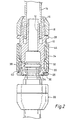
- hose coupling comprises a body 10 moulded from a synthetic plastics material.
- the body 10 has a through bore 12 one end of which is shown in Figure 1 communicating with a hose pipe 14.
- the end of the hose pipe 14 is detachably connected to the body 10 by means of a plurality of fingers 16 clamped against the outside of the hose pipe 14 by means of a tightening ring 18.
- the bore 12 is enlarged to receive the spigot 20 ( Figures 2 to 4) of a co- operating male hose coupling 22.
- An outer sleeve 24 surrounds the body 10 and is arranged to be axially movable between its normal locking position shown in Figures 1 to 3 and a release position shown in Figure 4.
- the lower end of the sleeve 24 as viewed in the drawings engages a ring 26 which is fixed on the body 10.
- the upper end of the sleeve 24 as shown in the drawings engages an annular ring 28 on the body 10, as illustrated in Figure 4.
- the lower end of the body 10 has three slots 30 which are equi-angularly spaced around the central axis X-X of the coupling and which run out to the lower end of the body 10, leaving between the slots 30, three downwardly projecting tongues 32.
- the extremity of each tongue 32 is shaped to form a toe 34 which engages with a snap action behind an annular ledge 36 formed on the ring 26.
- the spigot 20 is retained in the body 10 by means of three locking members 38 integrally formed with the ring 26.
- Each locking member 38 is connected to the ring 26 by a web 40 which is capable of flexing movement, and therefore acts in the manner of a hinge, by virtue of the inherent flexibility of the material from which the ring 26 and the locking members 38 are moulded.
- Each locking member 38 projects through a corresponding one of the slots 30 in the body 10 in order to engage the spigot 20 and lock the latter in position, as illustrated in Figure 3.
- Each web 40 extends between a corresponding pair of lugs 42 (best shown in Figure 1) which project radially inwardly from, and are integrally moulded with, the sleeve 24.
- the locking members 38 project into the bore of the member 10, and the upper edges of the lugs 42 engage the undersides of the locking members 38.
- This interengagement biases the sleeve 24 towards the normal locking position shown in Figures 1 to 3.
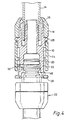
- this biasing effect may be provided by a helical compression spring acting between the body 10 and the sleeve 24, as illustrated by way of example at 44 in Figure 2.
- Figure 2 shows how the spigot 20 is simply pushed into the body 10 in order to join the male coupling 22 to the female coupling forming the preferred embodiment of the invention.
- the locking members 38 are pushed radially outwardly with attendant flexing of the webs 40, until the resilience of the webs 40 causes the locking members 38 to snap into engagement with the groove 45 in the spigot 20, as illustrated in Figure 3. It is not necessary to move the sleeve 24 to achieve interconnection.
- the sleeve 24 is moved to its release position shown in Figure 4. This axial movement of the sleeve 24 causes the upper surfaces of the lugs 42 to engage and swing the locking members 38 radially outwardly in order to release the locking members 38 from the groove 45.
- the spigot 20 may then simply be withdrawn from the body 10.
- the sleeve 24 When the sleeve 24 is released it moves back to its normal locking position as the locking members 38 swing back to their normal locking positions in which they project into the bore in the body 10. This return of the sleeve 24 to its locking position, and the return of the locking members 38 to their locking positions, occurs as a result of the natural tendency of the webs 40 to regain their original positions.
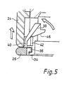
- each locking member 38 is shaped so that when the sleeve 24 is moved to its release position the cooperating upper surfaces of the lugs 42 engage and displace the locking inserts 38 with a suitable camming action which deflects the locking members 38 and moves them to their release positions, as indicated by the arrows in Figure 5.
- the locking members 38 are also shaped such that, with the spigot 20 engaged in the body 10, any tendency to withdraw the spigot 20 from the body 10 causes the locking members 38 to move radially inwardly and thereby increase their locking action.
- the body 10 sleeve 24 and ring 26 are made so that the coupling can be assembled with a simple snap action. This is done by mounting the ring 26 on a mandrel which holds the locking members in a radially outwardly deflected condition and then sliding the sleeve 24 into position so that the lugs 42 embrace the webs 40. The body 10 is then pushed downwardly into the assembly of the sleeve 24 and ring 26 until the toes 34 engage the ledges 36 with a snap action which then holds the components 10, 24 and 26 in position.
Landscapes
- Engineering & Computer Science (AREA)
- General Engineering & Computer Science (AREA)
- Mechanical Engineering (AREA)
- Rigid Pipes And Flexible Pipes (AREA)
- Examining Or Testing Airtightness (AREA)
- Forklifts And Lifting Vehicles (AREA)
- Quick-Acting Or Multi-Walled Pipe Joints (AREA)
Claims (11)
Priority Applications (1)
| Application Number | Priority Date | Filing Date | Title |
|---|---|---|---|
| AT86304241T ATE40919T1 (de) | 1985-06-11 | 1986-06-04 | Rohrkupplung. |
Applications Claiming Priority (2)
| Application Number | Priority Date | Filing Date | Title |
|---|---|---|---|
| GB858514678A GB8514678D0 (en) | 1985-06-11 | 1985-06-11 | Hose coupling |
| GB8514678 | 1985-06-11 |
Publications (3)
| Publication Number | Publication Date |
|---|---|
| EP0206582A2 EP0206582A2 (fr) | 1986-12-30 |
| EP0206582A3 EP0206582A3 (en) | 1987-04-01 |
| EP0206582B1 true EP0206582B1 (fr) | 1989-02-22 |
Family
ID=10580508
Family Applications (1)
| Application Number | Title | Priority Date | Filing Date |
|---|---|---|---|
| EP86304241A Expired EP0206582B1 (fr) | 1985-06-11 | 1986-06-04 | Raccord pour tuyaux |
Country Status (7)
| Country | Link |
|---|---|
| US (1) | US4673199A (fr) |
| EP (1) | EP0206582B1 (fr) |
| AT (1) | ATE40919T1 (fr) |
| AU (1) | AU581088B2 (fr) |
| DE (1) | DE3662161D1 (fr) |
| GB (1) | GB8514678D0 (fr) |
| ZA (1) | ZA864077B (fr) |
Families Citing this family (41)
| Publication number | Priority date | Publication date | Assignee | Title |
|---|---|---|---|---|
| US5083433A (en) * | 1987-06-04 | 1992-01-28 | Automotive Products Plc | Prefilled hydraulic actuator apparatus with separate reservoir and quick-connect between them |
| US4899792A (en) * | 1988-02-29 | 1990-02-13 | Emco Wheaton, Inc. | Fueling nozzle providing combination breakaway and swivel coupling |
| IT1220749B (it) * | 1988-05-04 | 1990-06-21 | Uniflex Utilime Spa | Innesto rapido per la giunzione scioglibile di tubi |
| US4944537A (en) * | 1988-06-13 | 1990-07-31 | Usui Kokusai Sangyo Kaisha Ltd. | Small-diameter pipe connector |
| US5090748A (en) * | 1988-07-29 | 1992-02-25 | Usui Kokusai Sangyo Kaisha Ltd. | Small-size piping coupling joint |
| US5048875A (en) * | 1989-01-18 | 1991-09-17 | Usui Kokusai Sangyo Daisha Limited | Connector interposed between small-diameter metallic pipe and flexible hose |
| US5112084A (en) * | 1989-02-07 | 1992-05-12 | Usui Kokusai Sangyo Kaisha, Ltd. | Connector for small-diameter piping |
| US4890866A (en) * | 1989-03-14 | 1990-01-02 | Mentor Corporation | Tubing connector |
| JP2767613B2 (ja) * | 1989-07-07 | 1998-06-18 | 臼井国際産業株式会社 | 細径配管接続用コネクター |
| JP2767619B2 (ja) * | 1989-08-23 | 1998-06-18 | 臼井国際産業株式会社 | 細径配管端部相互のコネクター |
| JP2802944B2 (ja) * | 1989-09-27 | 1998-09-24 | 臼井国際産業株式会社 | 細径配管接続用コネクター |
| JP2530220Y2 (ja) * | 1990-01-10 | 1997-03-26 | 臼井国際産業株式会社 | 細径配管接続用コネクター |
| JP3059184B2 (ja) * | 1990-01-20 | 2000-07-04 | 臼井国際産業株式会社 | 細径配管接続用コネクター |
| JP2935719B2 (ja) * | 1990-01-20 | 1999-08-16 | 臼井国際産業株式会社 | 細径配管接続用コネクター |
| JP2528256Y2 (ja) * | 1990-03-19 | 1997-03-05 | 臼井国際産業株式会社 | 細径配管接続用継手 |
| US5141264A (en) * | 1990-03-19 | 1992-08-25 | Usui Kokusai Sangyo Kaisha Ltd. | Connector for connecting thin tube |
| JP2556210Y2 (ja) * | 1990-03-19 | 1997-12-03 | 臼井国際産業 株式会社 | 細径配管接続用継手 |
| JP3031959B2 (ja) * | 1990-05-30 | 2000-04-10 | 臼井国際産業株式会社 | 配管接続用コネクター |
| GB9014748D0 (en) * | 1990-07-03 | 1990-08-22 | Hamble Aerostructures | Support arrangement |
| US5211427A (en) * | 1990-12-22 | 1993-05-18 | Usui Kokusai Sangyo Kaisha Ltd. | Piping connector |
| DE4100837A1 (de) * | 1991-01-14 | 1992-07-16 | Volker Bertram | Adaptor mit trachealtubus |
| JP3071498B2 (ja) * | 1991-05-30 | 2000-07-31 | 臼井国際産業株式会社 | 配管用コネクタ |
| JP3104929B2 (ja) * | 1992-03-11 | 2000-10-30 | 臼井国際産業株式会社 | 細径配管接続継手 |
| DE69720570T2 (de) * | 1996-01-23 | 2003-11-27 | Terumo K.K., Tokio/Tokyo | Injektor |
| JP3524676B2 (ja) * | 1996-04-18 | 2004-05-10 | 臼井国際産業株式会社 | 細径配管接続用コネクター |
| DE19915291A1 (de) * | 1999-04-03 | 2000-10-05 | Gardena Kress & Kastner Gmbh | Fluid-Kupplungsanordnung |
| DE10355535B4 (de) * | 2003-11-27 | 2009-08-27 | A. Raymond Et Cie | Vorrichtung zum abgedichteten Verbinden von zwei Endstücken |
| WO2012012849A1 (fr) * | 2010-07-30 | 2012-02-02 | Bryan James Messenger | Capuchon de robinet |
| GB201019591D0 (en) | 2010-11-19 | 2010-12-29 | Finian John | Adjustable collar |
| GB2501878B (en) | 2012-05-08 | 2015-12-09 | Elektron Technology Uk Ltd | Locking connector |
| GB2537902A (en) * | 2015-04-30 | 2016-11-02 | M-Flow Tech Ltd | Composite Fluid Conduit Assembly |
| US10030796B2 (en) | 2015-06-30 | 2018-07-24 | Cnh Industrial America Llc | Vacuum hose coupling with quick lock feature |
| ES2905895T3 (es) | 2017-04-05 | 2022-04-12 | Coloplast As | Implante de pene con tubo de longitud ajustable |
| GB2597494B (en) | 2020-07-23 | 2022-12-21 | Reliance Worldwide Corporation Uk Ltd | A plumbing connector |
| GB2597493A (en) | 2020-07-23 | 2022-02-02 | Reliance Worldwide Corporation Uk Ltd | A plumbing connector |
| FR3119657A1 (fr) * | 2021-02-05 | 2022-08-12 | Staubli Faverges | Elément de raccord |
| USD1097081S1 (en) | 2021-10-05 | 2025-10-07 | Reliance Worldwide Corporation (UK) Limited | Connector |
| GB2625100A (en) | 2022-12-06 | 2024-06-12 | Reliance Worldwide Corporation Uk Ltd | A plumbing connector |
| GB2637127A (en) | 2023-12-22 | 2025-07-16 | Reliance Worldwide Corporation Uk Ltd | A plumbing connector |
| US20250264174A1 (en) * | 2024-02-21 | 2025-08-21 | Kody J. Ketterling | Bidirectionally operable quick coupler assembly |
| USD1109853S1 (en) | 2024-10-17 | 2026-01-20 | Telebrands Corp. | Hose quick connect device |
Family Cites Families (9)
| Publication number | Priority date | Publication date | Assignee | Title |
|---|---|---|---|---|
| US2327611A (en) * | 1941-09-30 | 1943-08-24 | Albert T Schelwer | Coupling |
| US2344740A (en) * | 1942-08-01 | 1944-03-21 | Keller Tool Co | Hose coupling device |
| FR2230927B1 (fr) * | 1973-05-25 | 1980-03-28 | Utilisation Ration Gaz | |
| US3873062A (en) * | 1973-11-30 | 1975-03-25 | Jerry Lynn Johnson | Air hose quick coupler |
| CH578706A5 (en) * | 1974-06-14 | 1976-08-13 | Schild Sa A | Plug-in pipe union - has hooked locking insert engaging behind edge on taper-ended nipple |
| IT1086546B (it) * | 1977-05-23 | 1985-05-28 | Uniflex Spa | Giunto per tubi flessibili ad aggancio e sgancio rapido |
| IT1103793B (it) * | 1978-10-04 | 1985-10-14 | Ciccolallo Gino | Perfezionamenti nei giunti rapidi ad innesto automatico |
| US4216982A (en) * | 1978-12-26 | 1980-08-12 | Beatrice Foods Co. | Speed slip-on hose coupler |
| AU8722382A (en) * | 1981-08-21 | 1983-02-24 | Wilkinson Sword Ltd. | Snap-in coupling |
-
1985
- 1985-06-11 GB GB858514678A patent/GB8514678D0/en active Pending
-
1986
- 1986-05-30 ZA ZA864077A patent/ZA864077B/xx unknown
- 1986-06-02 AU AU58255/86A patent/AU581088B2/en not_active Ceased
- 1986-06-04 AT AT86304241T patent/ATE40919T1/de not_active IP Right Cessation
- 1986-06-04 US US06/870,725 patent/US4673199A/en not_active Expired - Lifetime
- 1986-06-04 DE DE8686304241T patent/DE3662161D1/de not_active Expired
- 1986-06-04 EP EP86304241A patent/EP0206582B1/fr not_active Expired
Also Published As
| Publication number | Publication date |
|---|---|
| AU581088B2 (en) | 1989-02-09 |
| DE3662161D1 (en) | 1989-03-30 |
| EP0206582A3 (en) | 1987-04-01 |
| ZA864077B (en) | 1987-01-28 |
| AU5825586A (en) | 1986-12-18 |
| ATE40919T1 (de) | 1989-03-15 |
| GB8514678D0 (en) | 1985-07-10 |
| US4673199A (en) | 1987-06-16 |
| EP0206582A2 (fr) | 1986-12-30 |
Similar Documents
| Publication | Publication Date | Title |
|---|---|---|
| EP0206582B1 (fr) | Raccord pour tuyaux | |
| US4591192A (en) | Quick connect coupling | |
| US4561682A (en) | Quick connect coupling | |
| CA1288451C (fr) | Raccords a fixation rapide, surtout pour tuyaux souples | |
| US4541657A (en) | Quick release hose coupling | |
| US4114853A (en) | Quick connect coupling | |
| US4275907A (en) | Quick connectable coupling | |
| US4014467A (en) | Dishwasher and coupling | |
| US4550967A (en) | Electrical connector member | |
| US4451069A (en) | Quick connect fluid coupling | |
| US5586792A (en) | Quick connector with integral release mechanism | |
| US4872710A (en) | Releasable quick connect fitting | |
| US6710685B1 (en) | Waveguide interconnection system | |
| US3403930A (en) | Device for self-locking and quick-unlocking of two parts, more particularly of electrical connectors | |
| US3810073A (en) | Connector locking mechanism | |
| US5366262A (en) | Quick connect fluid fitting | |
| US4216982A (en) | Speed slip-on hose coupler | |
| GB2236567A (en) | A hose coupling | |
| MY109237A (en) | Jointing device for a corrugated flexible conduit | |
| EP1104530A1 (fr) | Dispositif de couplage | |
| GB1558495A (en) | Multiple-passage plug-in coupling | |
| GB2328483A (en) | Plastic pipe compression coupler | |
| US6168212B1 (en) | Twist-lock connector for adjustably interlocking telescopic tubular members | |
| GB2068490A (en) | Hydraulic coupling device | |
| EP0126112B1 (fr) | Raccord de tuyau |
Legal Events
| Date | Code | Title | Description |
|---|---|---|---|
| PUAI | Public reference made under article 153(3) epc to a published international application that has entered the european phase |
Free format text: ORIGINAL CODE: 0009012 |
|
| AK | Designated contracting states |
Kind code of ref document: A2 Designated state(s): AT BE CH DE FR GB IT LI LU NL SE |
|
| PUAL | Search report despatched |
Free format text: ORIGINAL CODE: 0009013 |
|
| AK | Designated contracting states |
Kind code of ref document: A3 Designated state(s): AT BE CH DE FR GB IT LI LU NL SE |
|
| 17P | Request for examination filed |
Effective date: 19870422 |
|
| 17Q | First examination report despatched |
Effective date: 19870804 |
|
| ITF | It: translation for a ep patent filed | ||
| GRAA | (expected) grant |
Free format text: ORIGINAL CODE: 0009210 |
|
| AK | Designated contracting states |
Kind code of ref document: B1 Designated state(s): AT BE CH DE FR GB IT LI LU NL SE |
|
| PG25 | Lapsed in a contracting state [announced via postgrant information from national office to epo] |
Ref country code: SE Effective date: 19890222 Ref country code: LI Effective date: 19890222 Ref country code: CH Effective date: 19890222 Ref country code: BE Effective date: 19890222 Ref country code: AT Effective date: 19890222 |
|
| REF | Corresponds to: |
Ref document number: 40919 Country of ref document: AT Date of ref document: 19890315 Kind code of ref document: T |
|
| REF | Corresponds to: |
Ref document number: 3662161 Country of ref document: DE Date of ref document: 19890330 |
|
| ET | Fr: translation filed | ||
| REG | Reference to a national code |
Ref country code: CH Ref legal event code: PL |
|
| PG25 | Lapsed in a contracting state [announced via postgrant information from national office to epo] |
Ref country code: LU Free format text: LAPSE BECAUSE OF NON-PAYMENT OF DUE FEES Effective date: 19890630 |
|
| PLBE | No opposition filed within time limit |
Free format text: ORIGINAL CODE: 0009261 |
|
| STAA | Information on the status of an ep patent application or granted ep patent |
Free format text: STATUS: NO OPPOSITION FILED WITHIN TIME LIMIT |
|
| 26N | No opposition filed | ||
| ITTA | It: last paid annual fee | ||
| REG | Reference to a national code |
Ref country code: GB Ref legal event code: IF02 |
|
| PGFP | Annual fee paid to national office [announced via postgrant information from national office to epo] |
Ref country code: DE Payment date: 20030729 Year of fee payment: 18 |
|
| PGFP | Annual fee paid to national office [announced via postgrant information from national office to epo] |
Ref country code: NL Payment date: 20030829 Year of fee payment: 18 |
|
| PGFP | Annual fee paid to national office [announced via postgrant information from national office to epo] |
Ref country code: GB Payment date: 20040603 Year of fee payment: 19 |
|
| PG25 | Lapsed in a contracting state [announced via postgrant information from national office to epo] |
Ref country code: NL Free format text: LAPSE BECAUSE OF NON-PAYMENT OF DUE FEES Effective date: 20050101 Ref country code: DE Free format text: LAPSE BECAUSE OF NON-PAYMENT OF DUE FEES Effective date: 20050101 |
|
| NLV4 | Nl: lapsed or anulled due to non-payment of the annual fee |
Effective date: 20050101 |
|
| REG | Reference to a national code |
Ref country code: FR Ref legal event code: ST |
|
| PG25 | Lapsed in a contracting state [announced via postgrant information from national office to epo] |
Ref country code: IT Free format text: LAPSE BECAUSE OF NON-PAYMENT OF DUE FEES;WARNING: LAPSES OF ITALIAN PATENTS WITH EFFECTIVE DATE BEFORE 2007 MAY HAVE OCCURRED AT ANY TIME BEFORE 2007. THE CORRECT EFFECTIVE DATE MAY BE DIFFERENT FROM THE ONE RECORDED. Effective date: 20050604 Ref country code: GB Free format text: LAPSE BECAUSE OF NON-PAYMENT OF DUE FEES Effective date: 20050604 |
|
| PGFP | Annual fee paid to national office [announced via postgrant information from national office to epo] |
Ref country code: FR Payment date: 20050609 Year of fee payment: 19 |
|
| REG | Reference to a national code |
Ref country code: FR Ref legal event code: RN |
|
| REG | Reference to a national code |
Ref country code: FR Ref legal event code: FC |
|
| PG25 | Lapsed in a contracting state [announced via postgrant information from national office to epo] |
Ref country code: FR Free format text: LAPSE BECAUSE OF NON-PAYMENT OF DUE FEES Effective date: 20060228 |
|
| GBPC | Gb: european patent ceased through non-payment of renewal fee |
Effective date: 20050604 |
|
| REG | Reference to a national code |
Ref country code: FR Ref legal event code: ST Effective date: 20060228 |