EP0206578A2 - Power system stabilizing apparatus - Google Patents
Power system stabilizing apparatus Download PDFInfo
- Publication number
- EP0206578A2 EP0206578A2 EP86304233A EP86304233A EP0206578A2 EP 0206578 A2 EP0206578 A2 EP 0206578A2 EP 86304233 A EP86304233 A EP 86304233A EP 86304233 A EP86304233 A EP 86304233A EP 0206578 A2 EP0206578 A2 EP 0206578A2
- Authority
- EP
- European Patent Office
- Prior art keywords
- power system
- power
- generator
- pss
- deviation
- Prior art date
- Legal status (The legal status is an assumption and is not a legal conclusion. Google has not performed a legal analysis and makes no representation as to the accuracy of the status listed.)
- Granted
Links
Images


Classifications
-
- H—ELECTRICITY
- H02—GENERATION; CONVERSION OR DISTRIBUTION OF ELECTRIC POWER
- H02P—CONTROL OR REGULATION OF ELECTRIC MOTORS, ELECTRIC GENERATORS OR DYNAMO-ELECTRIC CONVERTERS; CONTROLLING TRANSFORMERS, REACTORS OR CHOKE COILS
- H02P9/00—Arrangements for controlling electric generators for the purpose of obtaining a desired output
- H02P9/10—Control effected upon generator excitation circuit to reduce harmful effects of overloads or transients, e.g. sudden application of load, sudden removal of load, sudden change of load
- H02P9/105—Control effected upon generator excitation circuit to reduce harmful effects of overloads or transients, e.g. sudden application of load, sudden removal of load, sudden change of load for increasing the stability
Definitions
- This invention relates to a power system stabilizing apparatus with a power system stabilizer (PSS) for a synchronous generator.
- PSS power system stabilizer
- the automatic voltage regulators have been widely applied with the output thereof being transmitted to the exciter for controlling the field current in order to maintain the terminal voltage of synchronous generator at a constant predetermined level.
- AVR automatic voltage regulators
- the response of the AVR is too quick, a negative control.effect may take place in the synchronous generator, resulting in disorder of the overall system stabilization, therefore, the power system 4 stabilizing apparatus with PSS is applied to prevent such disorder effect.
- Fig. 1 shows a block diagram of the power system stabilizing apparatus for synchronous generator, which is disclosed in Japanese Patent Publication No. 53-44204 (1978).
- Fig. 1 designates an input terminal giving a deviation from the reference terminal voltage of a generator
- 2 designates PPS
- 3 designates the input terminal of the PPS
- 4 designates a damping circuit
- 5 designates an adder circuit subtracting the output of the damping circuit 4 from the sum of the deviation from the input terminal 1 and the output of the PSS
- 6 designates an AVR controlling an exciter 7 by the output of the above adder circuit 4 and 7 designates an exciter, which is controlled by the above AVR 6, so as to supply the field current to the generator (not shown)
- 2a designates a filter circuit which is used to define the domain range of the PSS 2 corresponding to input signals 3 of the PSS 2 and featured with the transfer function; where T R and T H are the time constants of the set filter constructing the above filter circuit 2a and of the high pass filter respectively.
- 2b is a phase compensation circuit for time delays of the AVR 6, the exciter 7, the generator, etc. and is a advance/delay circuit with an amplification effect, which is normally represented in the form; where K is a gain of PSS 2 while T 11 and T 12 arc a delay time constant and an advance time constant respectively.
- 2c designates a limiter which limits the output signals of the PSS 2 to be a signal level appropriate to the entire exciting system shown in Fig. 4.
- revolution deviation of the generator rotor, frequency deviation of the generator terminal voltage, output deviation of the generator itself, etc. are used as the input signals of the PPS 2.
- the input terminal receives the corresponding deviation signal, which is amplified by the AVR 6 and inputted to the exciter 7, where the deviation signal is further amplified, supplied to the field windings of the generator and so controlled that the deviation from its reference value of the generator terminal voltage returns to zero.
- the damping circuit 4 is used to stabilize the above control action and to feedback the output thereof to the adder circuit 5, as mentioned before.
- the output of the PSS 2 is added supplementarily to such a control in order to improve the stabilization of the power system.
- the filter circuit 2a cuts off direct current and high frequency portion of this input signal, which is then inputted to the amplification and phase compensation circuit 2b for amplification and phase compensation.
- the amplification and phase compensation circuit 2b is controlled to less than its appropriate level through the limiter 2c and then fed to the adder circuit 5, therefore, the output of the exciter 7 is controlled in such a manner that drift motion of the generator can be prevented.
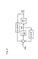
- Fig. 2 is showing a block diagram with linear approximation of drift motion of a generator representing a one-machine infinite system as described, for instance, in Bulletin of Electric Cooperative Researches, Vol. 34, No. 5.
- Fig. 2 is showing a block diagram with linear approximation of drift motion of a generator representing a one-machine infinite system as described, for instance, in Bulletin of Electric Cooperative Researches, Vol. 34, No. 5.
- K 1 means a synchronizing torque factor to be generated by a generator with constant field crossing fluxes
- K l ' means the synchronizing torque factor to be generated by the AVR
- K" means the synchronizing torque factor to be generated by the PSS 2
- D means a braking torque factor to be generated by the generator with constant field crossing fluxes
- D' means a braking torque factor to be generated by the AVR 6
- D" means a braking torque factor to be generated by the PSS 2.
- D' tends to take a negative value in cases where the phase angle 8 increases at the power factor being near to 1.0.
- the value of D+ D' becomes negative sometimes, resulting in failure of static stability due to insufficient braking power.
- the PSS 2 is added to generate the braking power D" for the stabilization required.
- Fig. 3 where the synchronizing torque and the braking torque are taken as the abscissa and the ordinate respectively.
- Both the synchronizing torque and the braking torque of a synchronous generator with constant field crossing fluxes are positive, and the sum of the torques (shown as K 1 +D) is found in the first quadrant, while the braking torque to be generated by the AVR 6 being negative, the sum of the braking torque and the synchronizing torque (shown as K 1 ' + D') is found in the forth quadrant and the sum of the torques generated by the AVR 6 and the generator with constant field crossing fluxes (shown as K 1 +K 1 '+D+D' )takes a value of approximately equal to zero or sometimes a negative value, resulting in failure of the static stabilization.
- This invention has an object to solve the problems described above and to provide a power system stabilizing apparatus for synchronous generator, which is provided with two PSSs, the characteristics of one PSS being preset so as to increase the braking power while the characteristics of the other PSS being preset to increase the synchronizing power and their phase compensation elements (time constants) can be varied in accordance with the drift amount, so that the synchronizing power in the transcient domain is increased sufficiently for improving the transcient stability while the braking power in the static domain is increased sufficiently for increasing the static stability.
- Fig. 4 shows a block diagram of the apparatus of the preset invention, wherein deviation of the terminal voltage of a synchronous generator (not shown) from its reference value is supplied to the input terminal 1 and added in the adder circuit 5 the outputs of the PSSs 2 and 8 and subtracted the output of the damping circuit 4.
- the output of the adder circuit 5 is given to the AVR 6, while an output required for making the terminal voltage of the synchronous generator reference value is given to an exciter 7, which supplies the corresponding exciting current to field windings of the synchronous generator.
- Both PSSs 2 and 8 are provided with filter circuits 2a and 8a, amplification and phase compensation circuits 2b and 8b and limiter circuits 2c and 8c respectively.
- the drift amount of the synchronous generator is given to input terminals 3 and 11 and outputs of the limiter 2c and 8c are inputted to the adder circuit 5, as described before.
- the PSS 2 is preset to have characteristics as shown in Fig. 3, that is, effectiveness for increasing the braking power.
- the PSS 8 has a preset characteristic for increasing the synchronizing power, namely, there being no difference of construction between the filter circuits 2a, 8a and the limiter circuits 2c, 8c, while the amplification and phase compensation circuit 8b having the transfer function; where C 2 is a constant, T 21 and T 22 are a delay time constant and an. advance time constant respectively. which is different from that of another amplification and phase compensation circuit 2b.
- the phase compensation elements (time constants) of these amplification and phase compensation circuits 2b and 8b can be varied and adjusted according to output of the drift amount judging circuit 9, as described later.
- the PSS 2 gives a sum of a braking torque for cancelling the braking torque generated by the AVR 6 and a synchronizing torque for increasing further the existing synchronizing power (shown as K 1 "+D"), resulting in the total sum of synchronizing torques (K 1 +K 1 '+K 1 "+D+D'+D") greater than K 1 +K 1 '+D+D'.
- the input terminal 11 of the first PSS 8 receives the revolution deviation of the.generator or the frequency deviation of the terminal voltage as drift amount of the synchronous generator, while the input terminal 3 of the second PSS 2 receives the output deviation of the synchronous generator.
- the drift amount judging circuit 9 judges whether the drift amount of the synchronous generator, i.e. the .revolution deviation of the generator, the frequency deviation of the terminal voltage or the output deviation of the generator exceeds a predetermined threshold value or not by using them as the input signals.
- the phase compensation elements (time constants) of amplification and phase compensation circuits 2b, 8b are so varied respectively for the phase compensation of the first PSS 8 to advance while the phase compensation of the second PSS 2 to delay.
- the phase compensation of the first PSS 8 is delayed while the phase of the second PSS 2 is advanced.
- the K I " value of the first PSS 8 increases according to the former's phase compensation, improving the synchronousstability in the transcient domain.
- the latter's phase compensation makes D" of the second PSS 8 increase, improving the stability in the static domain.
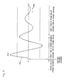
- Fig. 6 shows the relation between change of the revolution deviation ⁇ and phase advance and delay control of the both PSSs 2 and 8 in cases of a trouble in the system connected with the generator.
- the chain lines in Fig. 6 are showing the threshold values.
- the apparatus of this invention acts as follows; it is supposed that the revolution of deviation the generator is inputted to the input terminal 10 of the drift amount judging circuit 9 and the input terminal 11 of the first PSS 8.
- the revolution deviation ⁇ of the generator varies as shown in Fig. 6.
- the revolution deviation ⁇ of the generator takes the value of nearly zero in normal running conditions, where the phase compensation of the second PSS 2 is advanced to increase the braking power while the phase compensation of the first PSS 8 is delayed to increase the synchronizing power.
- the ⁇ change, as shown in Fig. 6, in system troubles is detected by the drift amount judging circuit 9 so that at the same time with the trouble occurrence, the phase compensation of the second PSS 2 is delayed while that of the first PSS 8 is advanced. This situation continues until the peak value of ⁇ exceeds a predetermined level and then each phase compensation is returned to the original value respectively.
- the above embodiment utilizes the switchover in two steps of each phase compensation element according to the revolution deviation, finer switchover in n steps gives the same effect, as described above.
- the number of revolution of the generator, the frequency of the terminal voltage, and the output of the generator itself can be inputted as the input signals to the first and second PSS 8 and 2, whereby the deviation signals are gained in each PSS 8 and 2.
Landscapes
- Engineering & Computer Science (AREA)
- Power Engineering (AREA)
- Control Of Eletrric Generators (AREA)
- Supply And Distribution Of Alternating Current (AREA)
Abstract
Description
- This invention relates to a power system stabilizing apparatus with a power system stabilizer (PSS) for a synchronous generator.
- The automatic voltage regulators (AVR) have been widely applied with the output thereof being transmitted to the exciter for controlling the field current in order to maintain the terminal voltage of synchronous generator at a constant predetermined level. However, if the response of the AVR is too quick, a negative control.effect may take place in the synchronous generator, resulting in disorder of the overall system stabilization, therefore, the
power system 4 stabilizing apparatus with PSS is applied to prevent such disorder effect. - Fig. 1 shows a block diagram of the power system stabilizing apparatus for synchronous generator, which is disclosed in Japanese Patent Publication No. 53-44204 (1978).
- Referring to Fig. 1, 1 designates an input terminal giving a deviation from the reference terminal voltage of a generator, 2 designates PPS, 3 designates the input terminal of the
PPS damping circuit 4 from the sum of the deviation from the input terminal 1 and the output of thePSS exciter 7 by the output of theabove adder circuit above AVR 6, so as to supply the field current to the generator (not shown), while 2a designates a filter circuit which is used to define the domain range of thePSS 2 corresponding toinput signals 3 of thePSS 2 and featured with the transfer function;
- On the other hand, 2b is a phase compensation circuit for time delays of the
AVR 6, the exciter 7, the generator, etc. and is a advance/delay circuit with an amplification effect, which is normally represented in the form;
PSS 2 while T11 and T12 arc a delay time constant and an advance time constant respectively. - Furtheremore, 2c designates a limiter which limits the output signals of the
PSS 2 to be a signal level appropriate to the entire exciting system shown in Fig. 4. Usually, revolution deviation of the generator rotor, frequency deviation of the generator terminal voltage, output deviation of the generator itself, etc. are used as the input signals of thePPS 2. - Now the actions will be described. When the terminal voltage of the generator deviates from its reference value, the input terminal receives the corresponding deviation signal, which is amplified by the
AVR 6 and inputted to theexciter 7, where the deviation signal is further amplified, supplied to the field windings of the generator and so controlled that the deviation from its reference value of the generator terminal voltage returns to zero. Thedamping circuit 4 is used to stabilize the above control action and to feedback the output thereof to theadder circuit 5, as mentioned before. The output of thePSS 2 is added supplementarily to such a control in order to improve the stabilization of the power system. - Supposing that the input signal to the
PSS 2 is a revolution deviation, the filter circuit 2a cuts off direct current and high frequency portion of this input signal, which is then inputted to the amplification andphase compensation circuit 2b for amplification and phase compensation. The amplification andphase compensation circuit 2b is controlled to less than its appropriate level through thelimiter 2c and then fed to theadder circuit 5, therefore, the output of theexciter 7 is controlled in such a manner that drift motion of the generator can be prevented. - Then, the principle of the
PSS 2 will be described. Fig. 2 is showing a block diagram with linear approximation of drift motion of a generator representing a one-machine infinite system as described, for instance, in Bulletin of Electric Cooperative Researches, Vol. 34, No. 5. In Fig. 2, K1 means a synchronizing torque factor to be generated by a generator with constant field crossing fluxes, Kl' means the synchronizing torque factor to be generated by the AVR and K" means the synchronizing torque factor to be generated by thePSS 2, while D means a braking torque factor to be generated by the generator with constant field crossing fluxes, D' means a braking torque factor to be generated by theAVR 6 and D" means a braking torque factor to be generated by thePSS 2. Moreover, - ΔTM indicates the mechanical input torque deviation,
- M indicates the inertial constant of the generator,
- Δw indicates the revolution deviation,
- wθ indicates the reference revolution and
- Δθ indicates the phase difference antle deviation.
- ΔTM,Δω and Δθ can be expressed in the differential equation undermentioned. The equation is in the same form of, so-called, the equation of motion of secondary system.

- This equation of motion abovementioned is Laplace- transformed into the transfer function, which is represented in Fig. 2. Since ΔTM is a torque, that is, an angle, acceleration power, Δω is a number of revolution, that is, an angle velocity, Δθ is an angle, it may be well concluded that the relationship among them is; the angle velocity is gained by integrating the angle acceleration force, and the angle is gained by integrating angle velocity. Accordingly, it can be said that both the blocks of 1 and ω0 in Ms s Fig. 2 represent integrators whose time constants are M 1 and- respectively. ω0
- Generally speaking, D' tends to take a negative value in cases where the
phase angle 8 increases at the power factor being near to 1.0. Particularly when theAVR 6 with quick response and high gain is used, the value of D+D' becomes negative sometimes, resulting in failure of static stability due to insufficient braking power. In such cases, thePSS 2 is added to generate the braking power D" for the stabilization required. - The above stabilizing effect is illustrated in Fig. 3, where the synchronizing torque and the braking torque are taken as the abscissa and the ordinate respectively. Both the synchronizing torque and the braking torque of a synchronous generator with constant field crossing fluxes are positive, and the sum of the torques (shown as K1+D) is found in the first quadrant, while the braking torque to be generated by the
AVR 6 being negative, the sum of the braking torque and the synchronizing torque (shown as K1'+D') is found in the forth quadrant and the sum of the torques generated by theAVR 6 and the generator with constant field crossing fluxes (shown as K1+K1'+D+D' )takes a value of approximately equal to zero or sometimes a negative value, resulting in failure of the static stabilization. When thePSS 2 gives a braking torque (whose sum with the synchronizing torque K" is shown as K1"+D") which cancels the braking torque of theAVR 6, the total sum of torques becomes K1+K1'+K1"+D+D'+D", namely, a conditon approximately identical with that in the absence of theAVR 6 is recovered for the stabilization control. - Nevertheless, it is impossible for the conventional PSS to realize the increased synchronizing power, which is needed to recover the static stabilization in a transcient domain where the generator drifts excessively immediately after an accident has taken place in the power system, because the conventional PSS have not originally been so contracted as to increase the synchronizing power and generally their synchronizing torque factor K1" is very small or negative as shown in Fig. 6.
- It can be concluded that a conventional power system stabilizing apparatus for a synchronous generator has problems in low transcient stability.
- This invention has an object to solve the problems described above and to provide a power system stabilizing apparatus for synchronous generator, which is provided with two PSSs, the characteristics of one PSS being preset so as to increase the braking power while the characteristics of the other PSS being preset to increase the synchronizing power and their phase compensation elements (time constants) can be varied in accordance with the drift amount, so that the synchronizing power in the transcient domain is increased sufficiently for improving the transcient stability while the braking power in the static domain is increased sufficiently for increasing the static stability.
- The above and further objects and features of the invention will more fully be apparent from the following detailed description with accompanying drawings.
-
- Fig. 1 shows a block diagram for a conventional power system stabilizing apparatus for a synchronous generator,
- Fig. 2 shows a block diagram with linear approximation of drift motion of a synchronous generator representing one machine infinite system,
- Fig. 3 shows a vector diagram explaining the torque characteristics of a conventional power system stabilizing apparatus,
- Fig. 4 shows a block diagram of a power system stabilizing apparatus for a synchronous generator of the present invention,
- Fig. 5 shows a vector diagram explaining the torque characteristics in a case of being connected PSS of increased synchronizing power, and
- Fig. 6 shows drift motion of a generator.
- Fig. 4 shows a block diagram of the apparatus of the preset invention, wherein deviation of the terminal voltage of a synchronous generator (not shown) from its reference value is supplied to the input terminal 1 and added in the
adder circuit 5 the outputs of thePSSs damping circuit 4. The output of theadder circuit 5 is given to theAVR 6, while an output required for making the terminal voltage of the synchronous generator reference value is given to anexciter 7, which supplies the corresponding exciting current to field windings of the synchronous generator. - Both
PSSs phase compensation circuits limiter circuits input terminals 3 and 11 and outputs of thelimiter adder circuit 5, as described before. Similarly to conventional apparatus shown in Fig. 1, thePSS 2 is preset to have characteristics as shown in Fig. 3, that is, effectiveness for increasing the braking power. - On the other hand, the
PSS 8 has a preset characteristic for increasing the synchronizing power, namely, there being no difference of construction between the filter circuits 2a, 8a and thelimiter circuits phase compensation circuit 8b having the transfer function;
which is different from that of another amplification andphase compensation circuit 2b. The phase compensation elements (time constants) of these amplification andphase compensation circuits - Then, Fig. 5 will be described, K1, K1', K1" and D, D', D" being defined in the same way as in Figs. 2 and 3, the sum of the torque generated by the
AVR 6 and the torque generated by the generator with constant field crossing fluxes (shown as K1+K1'+D+D') sometimes takes a value nearly equal to zero, in the same way as shown in Fig. 3. On the other hand, thePSS 2 gives a sum of a braking torque for cancelling the braking torque generated by theAVR 6 and a synchronizing torque for increasing further the existing synchronizing power (shown as K1"+D"), resulting in the total sum of synchronizing torques (K1+K1'+K1"+D+D'+D") greater than K1+K1'+D+D'. - Moreover, the input terminal 11 of the
first PSS 8 receives the revolution deviation of the.generator or the frequency deviation of the terminal voltage as drift amount of the synchronous generator, while theinput terminal 3 of thesecond PSS 2 receives the output deviation of the synchronous generator. - The reason why is explained as follows; the phase of the input signal of the
first PSS 8 side deviates from that of the second PSS2 side by 90 degrees. - The drift amount judging circuit 9 judges whether the drift amount of the synchronous generator, i.e. the .revolution deviation of the generator, the frequency deviation of the terminal voltage or the output deviation of the generator exceeds a predetermined threshold value or not by using them as the input signals. In a domain where the threshold value is exceeded, i.e., the transcient domain, the phase compensation elements (time constants) of amplification and
phase compensation circuits first PSS 8 to advance while the phase compensation of thesecond PSS 2 to delay. Reversely in a domain when the input signal is lower than the threshold value, i.e., the static domain, the phase compensation of thefirst PSS 8 is delayed while the phase of thesecond PSS 2 is advanced. The KI" value of thefirst PSS 8 increases according to the former's phase compensation, improving the synchronousstability in the transcient domain. The latter's phase compensation makes D" of thesecond PSS 8 increase, improving the stability in the static domain. - Fig. 6 shows the relation between change of the revolution deviation Δω and phase advance and delay control of the both PSSs 2 and 8 in cases of a trouble in the system connected with the generator. The chain lines in Fig. 6 are showing the threshold values.
- The apparatus of this invention with the construction as described above acts as follows; it is supposed that the revolution of deviation the generator is inputted to the input terminal 10 of the drift amount judging circuit 9 and the input terminal 11 of the
first PSS 8. When a trouble takes place in the power system, the revolution deviation Δω of the generator varies as shown in Fig. 6. The revolution deviation Δω of the generator takes the value of nearly zero in normal running conditions, where the phase compensation of thesecond PSS 2 is advanced to increase the braking power while the phase compensation of thefirst PSS 8 is delayed to increase the synchronizing power. - The Δω change, as shown in Fig. 6, in system troubles is detected by the drift amount judging circuit 9 so that at the same time with the trouble occurrence, the phase compensation of the
second PSS 2 is delayed while that of thefirst PSS 8 is advanced. This situation continues until the peak value of Δω exceeds a predetermined level and then each phase compensation is returned to the original value respectively. - These outputs of the
first PSS 2 and thesecond PSS 8 are added as the supplement signals of the exciting system to theadder circuit 5. This addition being so called a vector synthesis, the vector component of thefirst PSS 8 for increasing the synchronizing power becomes greater immediately after the trouble occurence, while the vector component of thesecond PSS 2 for increasing the braking power becomes greater during normal running conditions. - Though in the above embodiment the transcient and static domains of the drift of generator are judged with respect to the revolution deviation, the output deviation or the terminal voltage deviation of the generator is available for the judgement in the same way.
- Furthermore, the above embodiment utilizes the switchover in two steps of each phase compensation element according to the revolution deviation, finer switchover in n steps gives the same effect, as described above.
- And still more, the number of revolution of the generator, the frequency of the terminal voltage, and the output of the generator itself can be inputted as the input signals to the first and
second PSS PSS - As this invention may be embodied in several forms without departing from the spirit of essential characteristics thereof, the present embodiment is therefore illustrative and not restrictive, since the scope of the invention is defined by the appended claims rather than by the description preceding them, and all changes that fall within meets and bouds of the claims, or equivalence of such meets and bounds thereof are therefore intended to be embraced by the claims.
Claims (3)
Applications Claiming Priority (2)
| Application Number | Priority Date | Filing Date | Title |
|---|---|---|---|
| JP121917/85 | 1985-06-05 | ||
| JP60121917A JPS61280714A (en) | 1985-06-05 | 1985-06-05 | Power system stabilizer |
Publications (3)
| Publication Number | Publication Date |
|---|---|
| EP0206578A2 true EP0206578A2 (en) | 1986-12-30 |
| EP0206578A3 EP0206578A3 (en) | 1987-09-30 |
| EP0206578B1 EP0206578B1 (en) | 1991-02-27 |
Family
ID=14823108
Family Applications (1)
| Application Number | Title | Priority Date | Filing Date |
|---|---|---|---|
| EP86304233A Expired EP0206578B1 (en) | 1985-06-05 | 1986-06-04 | Power system stabilizing apparatus |
Country Status (4)
| Country | Link |
|---|---|
| US (1) | US4733156A (en) |
| EP (1) | EP0206578B1 (en) |
| JP (1) | JPS61280714A (en) |
| DE (1) | DE3677642D1 (en) |
Cited By (2)
| Publication number | Priority date | Publication date | Assignee | Title |
|---|---|---|---|---|
| EP0308621A3 (en) * | 1987-09-19 | 1989-10-18 | Mitsubishi Denki Kabushiki Kaisha | Power system stabilizer |
| EP0713287A1 (en) * | 1994-11-15 | 1996-05-22 | Kabushiki Kaisha Toshiba | Power system stabilizer for generator |
Families Citing this family (11)
| Publication number | Priority date | Publication date | Assignee | Title |
|---|---|---|---|---|
| US4999564A (en) * | 1989-10-12 | 1991-03-12 | General Electric Company | Power system stabilizer system having improved integrity checking scheme |
| US5440222A (en) * | 1991-07-15 | 1995-08-08 | Mitsubishi Denki Kabushiki Kaisha | Excitation control apparatus for synchronous machine |
| US5703791A (en) * | 1994-02-17 | 1997-12-30 | Hitachi, Ltd. | Electric power system stabilization control apparatus and method thereof |
| JP2846261B2 (en) * | 1994-11-30 | 1999-01-13 | 三菱電機株式会社 | Power system stabilizer |
| GB9610265D0 (en) * | 1996-05-16 | 1996-07-24 | Univ Manchester | Generator transfer function regulator |
| US5818208A (en) * | 1996-12-19 | 1998-10-06 | Abb Power T&D Company Inc. | Flicker controllers using voltage source converters |
| JP3435066B2 (en) * | 1998-07-31 | 2003-08-11 | 三菱電機株式会社 | Power system stabilizing apparatus and power system stabilizing method |
| US6819087B2 (en) * | 2002-12-27 | 2004-11-16 | General Electric Company | Distributed resource (DR) stabilization control for microgrid applications |
| US7904346B2 (en) * | 2002-12-31 | 2011-03-08 | Ebay Inc. | Method and system to adjust a seller fixed price offer |
| US7345456B2 (en) * | 2005-01-24 | 2008-03-18 | Basler Electric Company | Power system stabilizer providing excitation limiter functions |
| EP3347980B1 (en) | 2015-09-11 | 2024-05-22 | Wärtsilä Finland Oy | Method for controlling generator voltage |
Family Cites Families (8)
| Publication number | Priority date | Publication date | Assignee | Title |
|---|---|---|---|---|
| DE1238992B (en) * | 1963-11-16 | 1967-04-20 | Bbc Brown Boveri & Cie | Stability angle limiting controller for synchronous generators |
| CH514953A (en) * | 1970-04-20 | 1971-10-31 | Bbc Brown Boveri & Cie | Arrangement on a synchronous machine to stabilize its pole wheel movement |
| JPS5513240B2 (en) * | 1973-04-04 | 1980-04-07 | ||
| JPS5344204A (en) * | 1976-10-04 | 1978-04-20 | Kansai Paint Co Ltd | Method of producing photosensitive resin |
| JPS5574400A (en) * | 1978-11-30 | 1980-06-04 | Toshiba Corp | System stabilizer |
| JPS55160998A (en) * | 1979-06-01 | 1980-12-15 | Tokyo Electric Power Co Inc:The | Controller for synchronous machine |
| DE2945599C2 (en) * | 1979-11-12 | 1985-07-11 | Siemens AG, 1000 Berlin und 8000 München | Device for sway dampening of regulated electrical machines |
| DE3026360C2 (en) * | 1980-07-11 | 1985-01-17 | Siemens AG, 1000 Berlin und 8000 München | Circuit arrangement for damping power fluctuations from synchronous generators in networks |
-
1985
- 1985-06-05 JP JP60121917A patent/JPS61280714A/en active Granted
-
1986
- 1986-06-03 US US06/870,011 patent/US4733156A/en not_active Expired - Lifetime
- 1986-06-04 DE DE8686304233T patent/DE3677642D1/en not_active Expired - Lifetime
- 1986-06-04 EP EP86304233A patent/EP0206578B1/en not_active Expired
Cited By (3)
| Publication number | Priority date | Publication date | Assignee | Title |
|---|---|---|---|---|
| EP0308621A3 (en) * | 1987-09-19 | 1989-10-18 | Mitsubishi Denki Kabushiki Kaisha | Power system stabilizer |
| EP0713287A1 (en) * | 1994-11-15 | 1996-05-22 | Kabushiki Kaisha Toshiba | Power system stabilizer for generator |
| US5698968A (en) * | 1994-11-15 | 1997-12-16 | Kabushiki Kaisha Toshiba | Power system stabilizer for generator |
Also Published As
| Publication number | Publication date |
|---|---|
| EP0206578A3 (en) | 1987-09-30 |
| JPS61280714A (en) | 1986-12-11 |
| JPH0350492B2 (en) | 1991-08-01 |
| DE3677642D1 (en) | 1991-04-04 |
| US4733156A (en) | 1988-03-22 |
| EP0206578B1 (en) | 1991-02-27 |
Similar Documents
| Publication | Publication Date | Title |
|---|---|---|
| EP0206578A2 (en) | Power system stabilizing apparatus | |
| EP0308621B1 (en) | Power system stabilizer | |
| US4037144A (en) | Control device for use in shunt motor | |
| EP0688095B1 (en) | Variable speed generator-motor apparatus capable of improving accuracy of power system | |
| EP0570976B1 (en) | Electric power supply system | |
| EP0241920A2 (en) | Control system for PWM inverter | |
| EP0456521B1 (en) | Power system control apparatus | |
| US5256944A (en) | Motor speed control method and apparatus with drooping compensation independent of acceleration or deceleration current and time constant of motor | |
| US4859924A (en) | Inverter | |
| US3477014A (en) | Electrical control systems with stabilizing control means | |
| US4713741A (en) | Excitation control apparatus for rotary electric machine | |
| JPH01129800A (en) | Excitation controller for synchronous machine | |
| EP0682405B1 (en) | Apparatus for regulating an elevator motor | |
| JPS6057320B2 (en) | Grid stabilizer | |
| JP2540202B2 (en) | Correction control method in multivariable control system of generator | |
| EP0271777A2 (en) | Voltage protective apparatus for variable-frequency power system | |
| JPS6226279B2 (en) | ||
| JPH01186185A (en) | Speed controller for driving-motor | |
| JPS5976200A (en) | Exciter for synchronous machine | |
| JPS6160675B2 (en) | ||
| JP3092858B2 (en) | Grid stabilization system | |
| JP3355940B2 (en) | Phase adjustment transformer | |
| JPH0435973B2 (en) | ||
| JPH01117693A (en) | Load balancing controller | |
| JPH0474960B2 (en) |
Legal Events
| Date | Code | Title | Description |
|---|---|---|---|
| PUAI | Public reference made under article 153(3) epc to a published international application that has entered the european phase |
Free format text: ORIGINAL CODE: 0009012 |
|
| AK | Designated contracting states |
Kind code of ref document: A2 Designated state(s): CH DE GB LI |
|
| PUAL | Search report despatched |
Free format text: ORIGINAL CODE: 0009013 |
|
| AK | Designated contracting states |
Kind code of ref document: A3 Designated state(s): CH DE GB LI |
|
| 17P | Request for examination filed |
Effective date: 19871112 |
|
| 17Q | First examination report despatched |
Effective date: 19891208 |
|
| GRAA | (expected) grant |
Free format text: ORIGINAL CODE: 0009210 |
|
| AK | Designated contracting states |
Kind code of ref document: B1 Designated state(s): CH DE GB LI |
|
| REF | Corresponds to: |
Ref document number: 3677642 Country of ref document: DE Date of ref document: 19910404 |
|
| PLBE | No opposition filed within time limit |
Free format text: ORIGINAL CODE: 0009261 |
|
| STAA | Information on the status of an ep patent application or granted ep patent |
Free format text: STATUS: NO OPPOSITION FILED WITHIN TIME LIMIT |
|
| 26N | No opposition filed | ||
| PGFP | Annual fee paid to national office [announced via postgrant information from national office to epo] |
Ref country code: GB Payment date: 19920505 Year of fee payment: 7 |
|
| PG25 | Lapsed in a contracting state [announced via postgrant information from national office to epo] |
Ref country code: GB Effective date: 19930604 |
|
| GBPC | Gb: european patent ceased through non-payment of renewal fee |
Effective date: 19930604 |
|
| PGFP | Annual fee paid to national office [announced via postgrant information from national office to epo] |
Ref country code: DE Payment date: 20010528 Year of fee payment: 16 |
|
| PGFP | Annual fee paid to national office [announced via postgrant information from national office to epo] |
Ref country code: CH Payment date: 20010529 Year of fee payment: 16 |
|
| PG25 | Lapsed in a contracting state [announced via postgrant information from national office to epo] |
Ref country code: LI Free format text: LAPSE BECAUSE OF NON-PAYMENT OF DUE FEES Effective date: 20020630 Ref country code: CH Free format text: LAPSE BECAUSE OF NON-PAYMENT OF DUE FEES Effective date: 20020630 |
|
| PG25 | Lapsed in a contracting state [announced via postgrant information from national office to epo] |
Ref country code: DE Free format text: LAPSE BECAUSE OF NON-PAYMENT OF DUE FEES Effective date: 20030101 |
|
| REG | Reference to a national code |
Ref country code: CH Ref legal event code: PL |