EP3347980B1 - Method for controlling generator voltage - Google Patents
Method for controlling generator voltage Download PDFInfo
- Publication number
- EP3347980B1 EP3347980B1 EP15770554.2A EP15770554A EP3347980B1 EP 3347980 B1 EP3347980 B1 EP 3347980B1 EP 15770554 A EP15770554 A EP 15770554A EP 3347980 B1 EP3347980 B1 EP 3347980B1
- Authority
- EP
- European Patent Office
- Prior art keywords
- band
- synchronous generator
- power system
- voltage
- rejection filter
- Prior art date
- Legal status (The legal status is an assumption and is not a legal conclusion. Google has not performed a legal analysis and makes no representation as to the accuracy of the status listed.)
- Active
Links
- 238000000034 method Methods 0.000 title claims description 22
- 230000001360 synchronised effect Effects 0.000 claims description 86
- 239000003381 stabilizer Substances 0.000 claims description 40
- 230000005284 excitation Effects 0.000 claims description 36
- 230000010355 oscillation Effects 0.000 claims description 33
- 230000000087 stabilizing effect Effects 0.000 claims description 18
- 238000001228 spectrum Methods 0.000 claims description 13
- 238000004590 computer program Methods 0.000 claims description 8
- 230000005540 biological transmission Effects 0.000 claims description 7
- 230000004044 response Effects 0.000 claims description 6
- 238000013016 damping Methods 0.000 description 6
- 230000009471 action Effects 0.000 description 4
- 230000007246 mechanism Effects 0.000 description 4
- 230000002411 adverse Effects 0.000 description 3
- 230000008878 coupling Effects 0.000 description 2
- 238000010168 coupling process Methods 0.000 description 2
- 238000005859 coupling reaction Methods 0.000 description 2
- 238000004804 winding Methods 0.000 description 2
- 230000006978 adaptation Effects 0.000 description 1
- 230000003044 adaptive effect Effects 0.000 description 1
- 230000003750 conditioning effect Effects 0.000 description 1
- 230000001419 dependent effect Effects 0.000 description 1
- 238000001514 detection method Methods 0.000 description 1
- 230000000694 effects Effects 0.000 description 1
- 230000001747 exhibiting effect Effects 0.000 description 1
- 238000001914 filtration Methods 0.000 description 1
- 230000006870 function Effects 0.000 description 1
- 230000001629 suppression Effects 0.000 description 1
Images


Classifications
-
- H—ELECTRICITY
- H02—GENERATION; CONVERSION OR DISTRIBUTION OF ELECTRIC POWER
- H02P—CONTROL OR REGULATION OF ELECTRIC MOTORS, ELECTRIC GENERATORS OR DYNAMO-ELECTRIC CONVERTERS; CONTROLLING TRANSFORMERS, REACTORS OR CHOKE COILS
- H02P9/00—Arrangements for controlling electric generators for the purpose of obtaining a desired output
- H02P9/14—Arrangements for controlling electric generators for the purpose of obtaining a desired output by variation of field
- H02P9/26—Arrangements for controlling electric generators for the purpose of obtaining a desired output by variation of field using discharge tubes or semiconductor devices
- H02P9/30—Arrangements for controlling electric generators for the purpose of obtaining a desired output by variation of field using discharge tubes or semiconductor devices using semiconductor devices
- H02P9/302—Brushless excitation
-
- H—ELECTRICITY
- H02—GENERATION; CONVERSION OR DISTRIBUTION OF ELECTRIC POWER
- H02P—CONTROL OR REGULATION OF ELECTRIC MOTORS, ELECTRIC GENERATORS OR DYNAMO-ELECTRIC CONVERTERS; CONTROLLING TRANSFORMERS, REACTORS OR CHOKE COILS
- H02P9/00—Arrangements for controlling electric generators for the purpose of obtaining a desired output
- H02P9/10—Control effected upon generator excitation circuit to reduce harmful effects of overloads or transients, e.g. sudden application of load, sudden removal of load, sudden change of load
-
- G—PHYSICS
- G01—MEASURING; TESTING
- G01R—MEASURING ELECTRIC VARIABLES; MEASURING MAGNETIC VARIABLES
- G01R23/00—Arrangements for measuring frequencies; Arrangements for analysing frequency spectra
- G01R23/02—Arrangements for measuring frequency, e.g. pulse repetition rate; Arrangements for measuring period of current or voltage
Definitions
- the disclosure relates generally to an electrical power system comprising one or more synchronous generators. More particularly, the disclosure relates to a method for controlling the excitation of a synchronous generator, and to a voltage regulator for controlling the excitation of a synchronous generator. Furthermore, the disclosure relates to a computer program for configuring a voltage regulator of an electrical power system.
- an electrical power system for producing electrical energy comprises one or more prime movers arranged to rotate one or more synchronous generators.
- Each prime mover can be for example a turbine or a piston engine such as a diesel engine.
- the electrical power system comprises an excitation device configured to supply excitation current to the rotor winding of the synchronous generator under consideration.
- the excitation device can be for example a contactless rotating exciter or a slip-ring exciter.
- a control system of each synchronous generator comprises a voltage regulator for controlling the excitation device.
- the voltage regulator is often called an automatic voltage regulator "AVR".
- the voltage regulator is a part of a voltage control loop for controlling the excitation of the synchronous generator on the basis of actual and reference values of the amplitude of the generator voltage.
- a control system of a synchronous generator may further comprise a power system stabilizer "PSS" in parallel with the voltage regulator in order to enhance the dynamic stability of the electrical power system.
- Power system stabilizers have been shown to be effective in damping oscillations where instantaneous powers of synchronous generators or groups of synchronous generators oscillate with respect to each other. The frequency area of these oscillations can be e.g. from 0.3 Hz to 2 Hz.
- a power system stabilizer comprises typically a lead-lag circuit for modifying a signal indicative of deviation from synchronous operation, e.g. a signal indicative of deviation of a measured rotation speed from the nominal rotational speed.
- the lead-lag circuitry provides a phase-lead at the frequency area of the above-mentioned oscillations, and thus the lead-lag circuitry provides a good phase-margin on this frequency area. Therefore, the power system stabilizer "PSS" can be tuned to effectively suppress the above-mentioned oscillations.
- a control system of the kind described above is, however, not free from challenges.
- the power system stabilizer "PSS" may have an inverse effect on the damping of torsional mode oscillations that may occur in a rotating system comprising the rotor of a synchronous generator and a rotating part of a turbine or another prime mover.
- the prime mover is a four-stroke piston engine
- the lowest frequency component that is excited due to the nature of the engine is the half rotation frequency that is N/(2 ⁇ 60), where N is the rotational speed as revolutions per minute.
- Another frequency that can be harmful is the lowest natural torsion oscillation frequency.
- This natural frequency can be estimated by modelling the combination of the rotor of the synchronous generator and the rotating part of the prime mover as a two mass system comprising a flexible coupling.
- the above-mentioned natural frequency is: 1 2 ⁇ K c J M + J G J M J G , where Kc is the torsional elastic constant of the flexible coupling, J G is the moment of inertia of the rotor of the synchronous generator, and J M is the moment of inertia of the rotating part of the prime mover.
- Publications US4080559 and US4788653 describe control systems where a power system stabilizer "PSS" comprises a band-rejection filter.
- the stop-band of the band-rejection filter is arranged to cover the frequency area of the torsional mode oscillations.
- the band-rejection filter suppresses the frequency components related to the torsional mode oscillations, and therefore the adverse phenomenon where the power system stabilizer maintains or even amplifies the torsional mode oscillations can be avoided.
- Publication DE102008043203 describes a filter mechanism for filtering a generator output signal and exhibiting a pre-set filter characteristic e.g. band pass characteristic, with a cut-off frequency.
- a detection mechanism detects a frequency of the filtered output signal.
- An adaptation mechanism adapts the cut-off frequency of the filter mechanism depending on the detected frequency.
- FIG. 1a illustrates an electrical power system according to an exemplifying and non-limiting embodiment of the invention.
- the electrical power system can be, for example but not necessarily, an electrical power system of a ship or a diesel power plant.
- the electrical power system comprises a synchronous generator 101 that is driven by a prime mover 112.
- the synchronous generator 101 is configured to supply electrical power to a power grid 118.
- the prime mover 112 can be for example a diesel engine.
- An excitation device 124 is configured to supply excitation current to the rotor winding of the synchronous generator 101.
- the excitation device 124 can be for example a contactless rotating exciter or a slip-ring exciter.
- the electrical power system comprises a signal transducer 102 for producing an amplitude signal 113 indicative of the amplitude of the three-phase stator voltage of the synchronous generator 101.
- the amplitude signal 113 can be for example the length, i.e. the norm, of a space vector of the three-phase stator voltage.
- the amplitude signal 113 is substantially: 2 3 abs u a + a u b + a 2 u c , where u a , u b , and u c are instantaneous values of the stator phase voltages of the synchronous generator 101, a is a complex number (-1 + iV3)/2, and "abs" means the absolute value.
- the electrical power system comprises a band-rejection filter 104 having a stop-band that covers at least partly a frequency area of torsional mode oscillations that may take place in a rotating system that comprises the rotor of the synchronous generator 101 and a rotating part of the prime mover 112.
- the lower corner frequency of the above-mentioned stop-band can be for example on the range from 30 % to 70 % of f s /2p and the upper corner frequency of the stop-band can be on the range from 80 % to 150 % of the f s /2p, where f s is the nominal frequency of the voltage of the synchronous generator, typically 50 Hz or 60 Hz, and p is the number of pole pairs of the synchronous generator.
- f s /2p is the nominal half rotation frequency of the synchronous generator.
- the corner frequencies may represent e.g. a 3 dB suppression level.
- the band-rejection filter 104 is configured to output a filtered amplitude signal 114, and a subtraction element 115 is configured to form a difference 117 between the reference amplitude 116 of the generator voltage and the filtered amplitude signal 114.
- the filtered amplitude signal 114 is illustrated in figure element 122 in figure 1b . In the exemplifying situation presented in figure 1b , the filtered amplitude signal 114 is substantially constant.
- the electrical power system comprises a controller 103 for controlling the excitation device 124 on the basis of the above-mentioned difference 117.
- the controller 103 can be configured to carry out for example proportional P control, proportional and integrative PI control, proportional, integrative, and derivative PID control, or some other suitable control functionality.
- the signal transducer 102, the band-rejection filter 104, and the controller 103 are parts of a voltage control loop for controlling the excitation of the synchronous generator 101 on the basis of the amplitude signal 113 and the reference amplitude 116.
- the voltage control loop is illustrated with the aid of a dashed curve 119.
- the voltage control loop comprises the band-rejection filter 104, frequency components related to the torsional mode oscillations are suppressed in the voltage control loop and therefore adverse phenomena where the voltage control loop maintains or even amplifies the torsional mode oscillations can be avoided.
- FIG. 2 illustrates an electrical power system according to an exemplifying and non-limiting embodiment of the invention.
- the electrical power system comprises a synchronous generator 101, a signal transducer 102 for producing an amplitude signal 113 indicative of the amplitude of the voltage of the synchronous generator, and a controller 103 for controlling an excitation device 124 connected to the synchronous generator.
- the signal transducer 102 and the controller 103 are parts of a voltage control loop 119 for controlling the excitation of the synchronous generator on the basis of the amplitude signal 113 and the reference amplitude 116 of the generator voltage.
- the voltage control loop 119 further comprises a band-rejection filter 104.
- the stop-band of the band-rejection filter covers at least partly the frequency area of torsional mode oscillations of a rotating system comprising the rotor of the synchronous generator 101 and a rotating part of a prime mover 112.
- the voltage control loop further comprises a low-pass filter 206 for damping high-frequency signal components from the amplitude signal 113 and thereby high-frequency amplitude oscillations from the voltage of the synchronous generator 101.
- the exemplifying electrical power system illustrated in figure 2 comprises a power system stabilizer "PSS" 207 that receives a speed signal 225 from a speed sensor 223.
- the speed signal 225 is indicative of a measured rotational speed of the synchronous generator 101.
- the power system stabilizer 207 comprises typically a lead-lag circuitry for providing a phase-lead at a frequency area where the power system stabilizer is capable of damping oscillations.
- the power system stabilizer 207 is configured to form a stabilizing signal 226 on the basis of deviation of the measured rotational speed from the nominal rotational speed. At least a part of the information contained by the stabilizing signal 226 is conducted to the controller 103 via a summation element 229.
- the power system stabilizer 207 and the controller 103 are parts of a stabilizing control loop for controlling the excitation of the synchronous generator 101 on the basis of the deviation of the measured rotational speed from the nominal rotational speed.
- the stabilizing control loop is illustrated with a dashed curve 228.
- the stabilizing control loop 228 further comprises a band-rejection filter 204 having a stop-band covering at least partly the frequency area of the torsional mode oscillations of the rotating system.
- the band-rejection filter 204 suppresses the frequency components related to the torsional mode oscillations, and therefore the adverse phenomenon where the power system stabilizer 207 maintains or even amplifies the torsional mode oscillations can be avoided.
- the band-rejection filter 104 comprises one or more controllable components for implementing a changeable frequency response.
- the frequency response of the band-rejection filter 104 can be tuned to be suitable for different generator-prime mover combinations which may have different torsional oscillation characteristics.
- the electrical power system may further comprise a processing system 205 for computing the frequency spectrum of the amplitude signal 113 and for setting the band-rejection filter 104 to suppress one or more peaks belonging to a pre-determined frequency band of the computed frequency spectrum.
- the band-rejection filter 104 can be for example a digital filter that is capable of forming one or more changeable transmission zeros.
- the processing system 205 can be configured to set the band-rejection filter 104 to form the one or more changeable transmission zeros at one or more frequencies corresponding to the one or more peaks of the computed frequency spectrum.
- the frequency spectrum can be computed using a digital Fourier transform, e.g. the fast Fourier transform "FFT”.
- the band-rejection filter 204 can be a controllable filter and the band-rejection filter 204 can be controlled in the same way as the band-rejection filter 104.
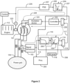
- FIG. 3 illustrates an electrical power system according to an exemplifying and non-limiting embodiment of the invention.
- the electrical power system comprises a synchronous generator 101, a signal transducer 102 for producing an amplitude signal 113 indicative of the amplitude of the voltage of the synchronous generator, and a controller 103 for controlling an excitation device 124 connected to the synchronous generator.
- the signal transducer 102 and the controller 103 are parts of a voltage control loop 119 for controlling the excitation of the synchronous generator on the basis of the amplitude signal 113 and the reference amplitude 116.
- the voltage control loop further comprises a band-rejection filter 304.
- the stop-band of the band-rejection filter covers at least partly the frequency area of torsional mode oscillations of a rotating system comprising the rotor of the synchronous generator 101 and a rotating part of a prime mover 112.
- the voltage control loop further comprises a low-pass filter 206 for damping high-frequency signal components from the amplitude signal 113 and thereby high-frequency amplitude oscillations from the voltage of the synchronous generator 101.
- the exemplifying electrical power system illustrated in figure 3 comprises a first power system stabilizer "PSS" 207 that receives a speed signal 225 from a speed sensor 223 and a second power system stabilizer "PSS" 307 that receives a frequency signal 330 from the signal transducer 102.
- the speed signal 225 is indicative of the measured rotational speed of the synchronous generator 101
- the frequency signal 330 is indicative of a measured frequency of the three-phase voltage of the synchronous generator 101.
- the signal transducer 102 is configured to produce, in addition to the amplitude signal 113, the frequency signal 330.
- the frequency can be measured for example based on the rotational speed of the space vector of the three-phase voltage.
- Each of the power system stabilizers 207 and 307 comprises typically a lead-lag circuitry for providing a phase-lead at a frequency area where the power system stabilizer under consideration is capable of damping oscillations.
- the power system stabilizer 207 is configured to form a first stabilizing signal 226 on the basis of deviation of the measured rotational speed from the nominal rotational speed
- the power system stabilizer 307 is configured to form a second stabilizing signal 331 on the basis of deviation of the measured frequency from the nominal frequency.
- the stabilizing signals 226 and 331 and a difference signal 117 related to the voltage control loop are supplied to a summation element 229.
- the power system stabilizer 207 and the controller 103 are parts of a first stabilizing control loop for controlling the excitation of the synchronous generator 101 on the basis of the deviation of the measured rotational speed from the nominal rotational speed
- the power system stabilizer 307 and the controller 103 are parts of a second stabilizing control loop for controlling the excitation on the basis of the deviation of the measured frequency from the nominal frequency.
- the first stabilizing control loop is illustrated with a dashed curve 228 and the second stabilizing control loop is illustrated with a dashed curve 332.
- the band-rejection filter 304 is between the summation element 229 and the controller 103. Therefore, the same band-rejection filter 304 is used both in the voltage control loop 119 and in the stabilizing control loops 228 and 332 for suppressing the frequency components related to the torsional oscillations.
- the band-rejection filter 304 is a linear filter
- the single filter arrangement shown in figure 3 operates in the same way as an arrangement where there are three separate band-rejection filters in the voltage control loop and in the stabilizing control loops in front of the summation element 229. If also the controller 103 is a linear element, the band-rejection filter 304 could be, in principle, after the controller.
- the first power system stabilizer 207 can be tuned to increase the synchronizing torque of the synchronous generator 101 and the second power system stabilizer 307 can be configured to increase the braking torque of the synchronous generator 101.
- M is related to the moment of inertia of the rotating system
- D represents the above-mentioned braking torque
- K represents the above-mentioned synchronizing torque
- ⁇ T represents fluctuation of the torque generated by the prime mover 112.
- the braking and synchronizing torques D and K are dependent on the properties of the synchronous generator, on the operating point of the synchronous generator, and on parameters of the voltage control loop and of the stabilizing control loops.
- FIG. 1a illustrates an exemplifying case where the band-rejection filter 104 is not a part of a voltage regulator 108.
- Figure 2 illustrates an exemplifying case where the band-rejection filter 104 and the low-pass filter 206 are parts of a voltage regulator 208.
- Figure 3 illustrates an exemplifying case where the band-rejection filter 304 and the low-pass filter 206 are parts of a voltage regulator 308 but the band-rejection filter is located in a different way than in the exemplifying case illustrated in figure 2 . It is also possible that the signal transducer 102 is a part of a voltage regulator.
- FIG. 4 illustrates a voltage regulator 408 according to an exemplifying and non-limiting embodiment of the invention.
- the voltage regulator comprises a first signal interface 409 for receiving an amplitude signal 113 that is indicative of the amplitude of the voltage of a synchronous generator.
- the voltage regulator comprises a signal transducer 102 for producing the amplitude signal 113 and thus the first signal interface 409 is an internal signal interface. It is, however, also possible that the voltage regulator does not comprise a signal transducer of the kind mentioned above and, in this case, the amplitude signal 113 is received from outside the voltage regulator.
- the voltage regulator comprises a second signal interface 410 for connecting to an excitation device connected to the synchronous generator.
- the voltage regulator comprises a controller 103 for constituting a part of a voltage control loop for controlling the excitation of the synchronous generator on the basis of the amplitude signal 113 and the reference amplitude 116 of the voltage.
- the reference amplitude 116 is received at a data interface 433.
- the voltage regulator comprises a band-rejection filter 104 for constituting another part of the above-mentioned voltage control loop.
- the lower corner frequency of the stop-band of the band-rejection filter 104 can be on the range from 30 % to 70 % of f s /2p and the upper corner frequency of the stop-band can be on the range from 80 % to 150 % of the f s /2p, where f s is the nominal frequency of the voltage of the synchronous generator, e.g. 50 Hz or 60 Hz, and p is a positive integer that represents the number of pole pairs of the synchronous generator. Thus, f s /2p is the nominal half rotation frequency of the synchronous generator.
- the band-rejection filter 104 comprises one or more controllable components for implementing a changeable frequency response.
- a voltage regulator further comprises a processing system 205 for computing a frequency spectrum of the amplitude signal 113 and for setting the band-rejection filter 104 to suppress one or more peaks belonging to a pre-determined frequency band of the frequency spectrum.
- a voltage regulator according to an exemplifying and non-limiting embodiment of the invention further comprises a low-pass filter 206 for constituting a part of the voltage control loop.
- a voltage regulator according to an exemplifying and non-limiting embodiment of the invention further comprises one or more third signal interfaces 411 for receiving one or more stabilizer signals produced by one or more power system stabilizers "PSS".
- the controller 103 is a part of the one or more stabilizing control loops each comprising one of the power system stabilizers.
- signal processing elements such as the band-rejection filter and the controller
- DSP digital signal processing circuits
- Each digital signal processing circuit as well as the processing system 205 shown in figures 2 and 4 can be implemented with one or more processor circuits, each of which can be a programmable processor circuit provided with appropriate software, a dedicated hardware processor such as, for example, an application specific integrated circuit "ASIC", or a configurable hardware processor such as, for example, a field programmable gate array "FPGA".
- ASIC application specific integrated circuit
- FPGA field programmable gate array
- a computer program comprises computer executable instructions for configuring a programmable digital signal processing "DSP" circuit of a voltage regulator to constitute a band-rejection filter which is a part of a voltage control loop for controlling the excitation of a synchronous generator on the basis of an amplitude signal and the reference amplitude, where the amplitude signal is indicative of the amplitude of generator voltage.
- DSP digital signal processing
- the above-mentioned executable instructions can be e.g. subroutines or functions implemented with a suitable programming language.
- a non-transitory computer readable medium e.g. a compact disc "CD”
- a data signal according to an exemplifying and non-limiting embodiment of the invention is encoded to carry information defining a computer program according to an exemplifying embodiment of invention.
- FIG. 5 is a flowchart of a method according to an exemplifying and non-limiting embodiment of the invention for controlling the excitation of a synchronous generator. The method comprises the following actions:
- the lower corner frequency of the stop-band of the band-rejection filter is on the range from 30 % to 70 % of f s /2p and the upper corner frequency of the stop-band of the band-rejection filter is on a range from 80 % to 150 % of the f s /2p, where f s is the nominal frequency of the voltage of the synchronous generator and p is the number of pole pairs of the synchronous generator.
- a method according to an exemplifying and non-limiting embodiment of the invention comprises tuning the band-rejection filter by changing settings of one or more controllable components of the band-rejection filter.
- a method further comprises computing the frequency spectrum of the amplitude signal and setting the band-rejection filter to suppress one or more peaks belonging to a pre-determined frequency band of the computed frequency spectrum.
- a method comprises setting the band-rejection filter to form one or more transmission zeros at one or more frequencies corresponding to the one or more peaks of the computed frequency spectrum.
- the voltage control loop comprises a low-pass filter.
- a method further comprises controlling the excitation of the synchronous generator with the aid of one or more power system stabilizers "PSS".
- PSS power system stabilizers
- Each power system stabilizer uses information indicative of deviation of a measured rotational speed of the synchronous generator from the nominal rotational speed, deviation of a measured frequency of the voltage from the nominal frequency, or some other suitable information indicative of deviation from synchronous operation.
- At least one of the power system stabilizers comprises a band-rejection filter having a stop-band covering at least partly the frequency area of the torsional mode oscillations of the rotating system.
- a first one of the power system stabilizers increases the synchronizing torque of the synchronous generator and a second one of the power system stabilizers increases the braking torque of the synchronous generator.
- the electrical power system is an electrical power system of a ship.
- a computer program according to an exemplifying and non-limiting embodiment of the invention comprises computer executable instructions for configuring one or more programmable digital signal processing "DSP" circuits of a voltage regulator of an electrical power system to carry out actions related to a method according to any of the above-described exemplifying embodiments of the invention.
- DSP digital signal processing
- the frequency components related to the torsional mode oscillations are suppressed with the aid of a band-rejection filter.
- the voltage control loop comprises some other signal conditioning device for suppressing the frequency components related to the torsional mode oscillations.
- These frequency components can be suppressed for example with a canceller device that is configured to form, with adaptive signal processing means, a cancelling signal and to add the cancelling signal to the signal under consideration so that the signal power on a desired frequency area related to the torsional mode oscillations is minimized.
Landscapes
- Engineering & Computer Science (AREA)
- Power Engineering (AREA)
- Physics & Mathematics (AREA)
- General Physics & Mathematics (AREA)
- Control Of Eletrric Generators (AREA)
Description
- The disclosure relates generally to an electrical power system comprising one or more synchronous generators. More particularly, the disclosure relates to a method for controlling the excitation of a synchronous generator, and to a voltage regulator for controlling the excitation of a synchronous generator. Furthermore, the disclosure relates to a computer program for configuring a voltage regulator of an electrical power system.
- In many cases, an electrical power system for producing electrical energy comprises one or more prime movers arranged to rotate one or more synchronous generators. Each prime mover can be for example a turbine or a piston engine such as a diesel engine. For each synchronous generator, the electrical power system comprises an excitation device configured to supply excitation current to the rotor winding of the synchronous generator under consideration. The excitation device can be for example a contactless rotating exciter or a slip-ring exciter. A control system of each synchronous generator comprises a voltage regulator for controlling the excitation device. The voltage regulator is often called an automatic voltage regulator "AVR". The voltage regulator is a part of a voltage control loop for controlling the excitation of the synchronous generator on the basis of actual and reference values of the amplitude of the generator voltage.
- A control system of a synchronous generator may further comprise a power system stabilizer "PSS" in parallel with the voltage regulator in order to enhance the dynamic stability of the electrical power system. Power system stabilizers have been shown to be effective in damping oscillations where instantaneous powers of synchronous generators or groups of synchronous generators oscillate with respect to each other. The frequency area of these oscillations can be e.g. from 0.3 Hz to 2 Hz. A power system stabilizer comprises typically a lead-lag circuit for modifying a signal indicative of deviation from synchronous operation, e.g. a signal indicative of deviation of a measured rotation speed from the nominal rotational speed. The lead-lag circuitry provides a phase-lead at the frequency area of the above-mentioned oscillations, and thus the lead-lag circuitry provides a good phase-margin on this frequency area. Therefore, the power system stabilizer "PSS" can be tuned to effectively suppress the above-mentioned oscillations.
- A control system of the kind described above is, however, not free from challenges. One of the challenges is that the power system stabilizer "PSS" may have an inverse effect on the damping of torsional mode oscillations that may occur in a rotating system comprising the rotor of a synchronous generator and a rotating part of a turbine or another prime mover. In a case where the prime mover is a four-stroke piston engine, the lowest frequency component that is excited due to the nature of the engine is the half rotation frequency that is N/(2 × 60), where N is the rotational speed as revolutions per minute. Another frequency that can be harmful is the lowest natural torsion oscillation frequency. This natural frequency can be estimated by modelling the combination of the rotor of the synchronous generator and the rotating part of the prime mover as a two mass system comprising a flexible coupling. In this model, the above-mentioned natural frequency is:

- Publications
US4080559 andUS4788653 describe control systems where a power system stabilizer "PSS" comprises a band-rejection filter. The stop-band of the band-rejection filter is arranged to cover the frequency area of the torsional mode oscillations. The band-rejection filter suppresses the frequency components related to the torsional mode oscillations, and therefore the adverse phenomenon where the power system stabilizer maintains or even amplifies the torsional mode oscillations can be avoided. - In conjunction with many electrical power systems, there is however still a need for techniques for controlling the excitation of synchronous generators so that the torsional mode oscillations are kept at a sufficiently low level. This need is present especially in electrical power systems of ships and in other small electrical power systems where load variations can be strong relative to the nominal power of the electrical power system.
- Publication
DE102008043203 describes a filter mechanism for filtering a generator output signal and exhibiting a pre-set filter characteristic e.g. band pass characteristic, with a cut-off frequency. A detection mechanism detects a frequency of the filtered output signal. An adaptation mechanism adapts the cut-off frequency of the filter mechanism depending on the detected frequency. - The present invention is defined in the independent claims 1,4 and 15.
- Exemplifying and non-limiting embodiments of the invention and their advantages are explained in greater detail below in the sense of examples and with reference to the accompanying drawings, in which:
-
figure 1a illustrates an electrical power system according to an exemplifying and non-limiting embodiment of the invention, -
figure 1b shows exemplifying signal waveforms appearing in the voltage control loop of the electrical power system illustrated infigure 1a , -
figure 2 illustrates an electrical power system according to an exemplifying and non-limiting embodiment of the invention, -
figure 3 illustrates an electrical power system according to an exemplifying and non-limiting embodiment of the invention, -
figure 4 illustrates a voltage regulator according to an exemplifying and non-limiting embodiment of the invention, and -
figure 5 is a flowchart of a method according to an exemplifying and non-limiting embodiment of the invention for controlling the excitation of a synchronous generator. - The specific examples provided in the description below should not be construed as limiting the scope and/or the applicability of the accompanied claims. Lists and groups of examples provided in the description are not exhaustive unless otherwise explicitly stated.
-
Figure 1a illustrates an electrical power system according to an exemplifying and non-limiting embodiment of the invention. The electrical power system can be, for example but not necessarily, an electrical power system of a ship or a diesel power plant. The electrical power system comprises asynchronous generator 101 that is driven by aprime mover 112. Thesynchronous generator 101 is configured to supply electrical power to apower grid 118. Theprime mover 112 can be for example a diesel engine. Anexcitation device 124 is configured to supply excitation current to the rotor winding of thesynchronous generator 101. Theexcitation device 124 can be for example a contactless rotating exciter or a slip-ring exciter. - The electrical power system comprises a
signal transducer 102 for producing anamplitude signal 113 indicative of the amplitude of the three-phase stator voltage of thesynchronous generator 101. Theamplitude signal 113 can be for example the length, i.e. the norm, of a space vector of the three-phase stator voltage. In this exemplifying case, theamplitude signal 113 is substantially:
synchronous generator 101, a is a complex number (-1 + iV3)/2, and "abs" means the absolute value. Exemplifying waveforms of the stator phase voltages ua, ub, and uc are presented infigure element 120 infigure 1b , and the corresponding waveform of theamplitude signal 113 is presented infigure element 121 infigure 1b . - The electrical power system comprises a band-
rejection filter 104 having a stop-band that covers at least partly a frequency area of torsional mode oscillations that may take place in a rotating system that comprises the rotor of thesynchronous generator 101 and a rotating part of theprime mover 112. The lower corner frequency of the above-mentioned stop-band can be for example on the range from 30 % to 70 % of fs/2p and the upper corner frequency of the stop-band can be on the range from 80 % to 150 % of the fs/2p, where fs is the nominal frequency of the voltage of the synchronous generator, typically 50 Hz or 60 Hz, and p is the number of pole pairs of the synchronous generator. Thus, fs/2p is the nominal half rotation frequency of the synchronous generator. The corner frequencies may represent e.g. a 3 dB suppression level. The band-rejection filter 104 is configured to output a filteredamplitude signal 114, and asubtraction element 115 is configured to form adifference 117 between thereference amplitude 116 of the generator voltage and the filteredamplitude signal 114. The filteredamplitude signal 114 is illustrated infigure element 122 infigure 1b . In the exemplifying situation presented infigure 1b , the filteredamplitude signal 114 is substantially constant. - The electrical power system comprises a
controller 103 for controlling theexcitation device 124 on the basis of the above-mentioneddifference 117. Thecontroller 103 can be configured to carry out for example proportional P control, proportional and integrative PI control, proportional, integrative, and derivative PID control, or some other suitable control functionality. As can be seen fromfigure 1a , thesignal transducer 102, the band-rejection filter 104, and thecontroller 103 are parts of a voltage control loop for controlling the excitation of thesynchronous generator 101 on the basis of theamplitude signal 113 and thereference amplitude 116. Infigure 1a , the voltage control loop is illustrated with the aid of a dashedcurve 119. As the voltage control loop comprises the band-rejection filter 104, frequency components related to the torsional mode oscillations are suppressed in the voltage control loop and therefore adverse phenomena where the voltage control loop maintains or even amplifies the torsional mode oscillations can be avoided. -
Figure 2 illustrates an electrical power system according to an exemplifying and non-limiting embodiment of the invention. The electrical power system comprises asynchronous generator 101, asignal transducer 102 for producing anamplitude signal 113 indicative of the amplitude of the voltage of the synchronous generator, and acontroller 103 for controlling anexcitation device 124 connected to the synchronous generator. Thesignal transducer 102 and thecontroller 103 are parts of avoltage control loop 119 for controlling the excitation of the synchronous generator on the basis of theamplitude signal 113 and thereference amplitude 116 of the generator voltage. Thevoltage control loop 119 further comprises a band-rejection filter 104. The stop-band of the band-rejection filter covers at least partly the frequency area of torsional mode oscillations of a rotating system comprising the rotor of thesynchronous generator 101 and a rotating part of aprime mover 112. In the exemplifying electrical power system illustrated infigure 2 , the voltage control loop further comprises a low-pass filter 206 for damping high-frequency signal components from theamplitude signal 113 and thereby high-frequency amplitude oscillations from the voltage of thesynchronous generator 101. - The exemplifying electrical power system illustrated in
figure 2 comprises a power system stabilizer "PSS" 207 that receives aspeed signal 225 from aspeed sensor 223. Thespeed signal 225 is indicative of a measured rotational speed of thesynchronous generator 101. Thepower system stabilizer 207 comprises typically a lead-lag circuitry for providing a phase-lead at a frequency area where the power system stabilizer is capable of damping oscillations. Thepower system stabilizer 207 is configured to form a stabilizingsignal 226 on the basis of deviation of the measured rotational speed from the nominal rotational speed. At least a part of the information contained by the stabilizingsignal 226 is conducted to thecontroller 103 via asummation element 229. As can be seen fromfigure 2 , thepower system stabilizer 207 and thecontroller 103 are parts of a stabilizing control loop for controlling the excitation of thesynchronous generator 101 on the basis of the deviation of the measured rotational speed from the nominal rotational speed. Infigure 2 , the stabilizing control loop is illustrated with a dashedcurve 228. - In the exemplifying electrical power system illustrated in
figure 2 , the stabilizingcontrol loop 228 further comprises a band-rejection filter 204 having a stop-band covering at least partly the frequency area of the torsional mode oscillations of the rotating system. The band-rejection filter 204 suppresses the frequency components related to the torsional mode oscillations, and therefore the adverse phenomenon where thepower system stabilizer 207 maintains or even amplifies the torsional mode oscillations can be avoided. - In the exemplifying electrical power system illustrated in
figure 2 , the band-rejection filter 104 comprises one or more controllable components for implementing a changeable frequency response. Thus, the frequency response of the band-rejection filter 104 can be tuned to be suitable for different generator-prime mover combinations which may have different torsional oscillation characteristics. The electrical power system may further comprise aprocessing system 205 for computing the frequency spectrum of theamplitude signal 113 and for setting the band-rejection filter 104 to suppress one or more peaks belonging to a pre-determined frequency band of the computed frequency spectrum. The band-rejection filter 104 can be for example a digital filter that is capable of forming one or more changeable transmission zeros. Theprocessing system 205 can be configured to set the band-rejection filter 104 to form the one or more changeable transmission zeros at one or more frequencies corresponding to the one or more peaks of the computed frequency spectrum. The frequency spectrum can be computed using a digital Fourier transform, e.g. the fast Fourier transform "FFT". Also the band-rejection filter 204 can be a controllable filter and the band-rejection filter 204 can be controlled in the same way as the band-rejection filter 104. -
Figure 3 illustrates an electrical power system according to an exemplifying and non-limiting embodiment of the invention. The electrical power system comprises asynchronous generator 101, asignal transducer 102 for producing anamplitude signal 113 indicative of the amplitude of the voltage of the synchronous generator, and acontroller 103 for controlling anexcitation device 124 connected to the synchronous generator. Thesignal transducer 102 and thecontroller 103 are parts of avoltage control loop 119 for controlling the excitation of the synchronous generator on the basis of theamplitude signal 113 and thereference amplitude 116. The voltage control loop further comprises a band-rejection filter 304. The stop-band of the band-rejection filter covers at least partly the frequency area of torsional mode oscillations of a rotating system comprising the rotor of thesynchronous generator 101 and a rotating part of aprime mover 112. In the exemplifying electrical power system illustrated infigure 3 , the voltage control loop further comprises a low-pass filter 206 for damping high-frequency signal components from theamplitude signal 113 and thereby high-frequency amplitude oscillations from the voltage of thesynchronous generator 101. - The exemplifying electrical power system illustrated in
figure 3 comprises a first power system stabilizer "PSS" 207 that receives aspeed signal 225 from aspeed sensor 223 and a second power system stabilizer "PSS" 307 that receives afrequency signal 330 from thesignal transducer 102. Thespeed signal 225 is indicative of the measured rotational speed of thesynchronous generator 101 and thefrequency signal 330 is indicative of a measured frequency of the three-phase voltage of thesynchronous generator 101. In this exemplifying case, thesignal transducer 102 is configured to produce, in addition to theamplitude signal 113, thefrequency signal 330. The frequency can be measured for example based on the rotational speed of the space vector of the three-phase voltage. Each of thepower system stabilizers power system stabilizer 207 is configured to form a first stabilizingsignal 226 on the basis of deviation of the measured rotational speed from the nominal rotational speed, and thepower system stabilizer 307 is configured to form a second stabilizingsignal 331 on the basis of deviation of the measured frequency from the nominal frequency. The stabilizing signals 226 and 331 and adifference signal 117 related to the voltage control loop are supplied to asummation element 229. As can be seen fromfigure 3 , thepower system stabilizer 207 and thecontroller 103 are parts of a first stabilizing control loop for controlling the excitation of thesynchronous generator 101 on the basis of the deviation of the measured rotational speed from the nominal rotational speed, and thepower system stabilizer 307 and thecontroller 103 are parts of a second stabilizing control loop for controlling the excitation on the basis of the deviation of the measured frequency from the nominal frequency. Infigure 3 , the first stabilizing control loop is illustrated with a dashedcurve 228 and the second stabilizing control loop is illustrated with a dashedcurve 332. - In the exemplifying electrical power system illustrated in
figure 3 , the band-rejection filter 304 is between thesummation element 229 and thecontroller 103. Therefore, the same band-rejection filter 304 is used both in thevoltage control loop 119 and in the stabilizingcontrol loops rejection filter 304 is a linear filter, the single filter arrangement shown infigure 3 operates in the same way as an arrangement where there are three separate band-rejection filters in the voltage control loop and in the stabilizing control loops in front of thesummation element 229. If also thecontroller 103 is a linear element, the band-rejection filter 304 could be, in principle, after the controller. - As presented in publication
US4733156 , the firstpower system stabilizer 207 can be tuned to increase the synchronizing torque of thesynchronous generator 101 and the secondpower system stabilizer 307 can be configured to increase the braking torque of thesynchronous generator 101. The synchronizing torque and the braking torque are illustrated by the following differential equation concerning the deviation of the power angle Δδ of the synchronous generator:
prime mover 112. The braking and synchronizing torques D and K are dependent on the properties of the synchronous generator, on the operating point of the synchronous generator, and on parameters of the voltage control loop and of the stabilizing control loops. - Practical implementations of electrical power systems of the kind described above comprise typically a voltage regulator that is often called an automatic voltage regulator "AVR". The above-mentioned band-rejection filter can be a part of the voltage regulator or the band-rejection filter can be an external element that is connected to the voltage regulator.
Figure 1a illustrates an exemplifying case where the band-rejection filter 104 is not a part of avoltage regulator 108.Figure 2 illustrates an exemplifying case where the band-rejection filter 104 and the low-pass filter 206 are parts of avoltage regulator 208.Figure 3 illustrates an exemplifying case where the band-rejection filter 304 and the low-pass filter 206 are parts of avoltage regulator 308 but the band-rejection filter is located in a different way than in the exemplifying case illustrated infigure 2 . It is also possible that thesignal transducer 102 is a part of a voltage regulator. -
Figure 4 illustrates avoltage regulator 408 according to an exemplifying and non-limiting embodiment of the invention. The voltage regulator comprises afirst signal interface 409 for receiving anamplitude signal 113 that is indicative of the amplitude of the voltage of a synchronous generator. In this exemplifying case, the voltage regulator comprises asignal transducer 102 for producing theamplitude signal 113 and thus thefirst signal interface 409 is an internal signal interface. It is, however, also possible that the voltage regulator does not comprise a signal transducer of the kind mentioned above and, in this case, theamplitude signal 113 is received from outside the voltage regulator. The voltage regulator comprises asecond signal interface 410 for connecting to an excitation device connected to the synchronous generator. The voltage regulator comprises acontroller 103 for constituting a part of a voltage control loop for controlling the excitation of the synchronous generator on the basis of theamplitude signal 113 and thereference amplitude 116 of the voltage. Thereference amplitude 116 is received at adata interface 433. The voltage regulator comprises a band-rejection filter 104 for constituting another part of the above-mentioned voltage control loop. The lower corner frequency of the stop-band of the band-rejection filter 104 can be on the range from 30 % to 70 % of fs/2p and the upper corner frequency of the stop-band can be on the range from 80 % to 150 % of the fs/2p, where fs is the nominal frequency of the voltage of the synchronous generator, e.g. 50 Hz or 60 Hz, and p is a positive integer that represents the number of pole pairs of the synchronous generator. Thus, fs/2p is the nominal half rotation frequency of the synchronous generator. - In a voltage regulator according to an exemplifying and non-limiting embodiment of the invention, the band-
rejection filter 104 comprises one or more controllable components for implementing a changeable frequency response. - A voltage regulator according to an exemplifying and non-limiting embodiment of the invention further comprises a
processing system 205 for computing a frequency spectrum of theamplitude signal 113 and for setting the band-rejection filter 104 to suppress one or more peaks belonging to a pre-determined frequency band of the frequency spectrum. - In a voltage regulator according to an exemplifying and non-limiting embodiment of the invention:
- the one or more controllable elements of the band-
rejection filter 104 are suitable for forming one or more changeable transmission zeros on the frequency response of the band-rejection filter, and - the
processing system 205 is configured to set the band-rejection filter 104 to form the one or more changeable transmission zeros at one or more frequencies corresponding to the one or more peaks of the frequency spectrum. - A voltage regulator according to an exemplifying and non-limiting embodiment of the invention further comprises a low-
pass filter 206 for constituting a part of the voltage control loop. - A voltage regulator according to an exemplifying and non-limiting embodiment of the invention further comprises one or more third signal interfaces 411 for receiving one or more stabilizer signals produced by one or more power system stabilizers "PSS". In a case where the one or more stabilizer signals are received at the one or more third signal interfaces 411, the
controller 103 is a part of the one or more stabilizing control loops each comprising one of the power system stabilizers. - The implementation of signal processing elements, such as the band-rejection filter and the controller, can be based on one or more analogue circuits, one or more digital signal processing "DSP" circuits, or a combination thereof. Each digital signal processing circuit as well as the
processing system 205 shown infigures 2 and4 can be implemented with one or more processor circuits, each of which can be a programmable processor circuit provided with appropriate software, a dedicated hardware processor such as, for example, an application specific integrated circuit "ASIC", or a configurable hardware processor such as, for example, a field programmable gate array "FPGA". - A computer program according to an exemplifying and non-limiting embodiment of the invention comprises computer executable instructions for configuring a programmable digital signal processing "DSP" circuit of a voltage regulator to constitute a band-rejection filter which is a part of a voltage control loop for controlling the excitation of a synchronous generator on the basis of an amplitude signal and the reference amplitude, where the amplitude signal is indicative of the amplitude of generator voltage.
- The above-mentioned executable instructions can be e.g. subroutines or functions implemented with a suitable programming language.
- A computer program product according to an exemplifying and non-limiting embodiment of the invention comprises a non-transitory computer readable medium, e.g. a compact disc "CD", encoded with a computer program according to an exemplifying embodiment of invention.
- A data signal according to an exemplifying and non-limiting embodiment of the invention is encoded to carry information defining a computer program according to an exemplifying embodiment of invention.
-
Figure 5 is a flowchart of a method according to an exemplifying and non-limiting embodiment of the invention for controlling the excitation of a synchronous generator. The method comprises the following actions: - action 501: producing an amplitude signal indicative of the amplitude of the voltage of the synchronous generator, and
- action 502: operating a voltage control loop for controlling the excitation of the synchronous generator on the basis of the amplitude signal and the reference amplitude of the voltage, where the voltage control loop comprises a band-rejection filter having a stop-band covering at least partly a frequency area of torsional mode oscillations of a rotating system comprising, inter alia, the rotor of the synchronous generator.
- In a method according to an exemplifying and non-limiting embodiment of the invention, the lower corner frequency of the stop-band of the band-rejection filter is on the range from 30 % to 70 % of fs/2p and the upper corner frequency of the stop-band of the band-rejection filter is on a range from 80 % to 150 % of the fs/2p, where fs is the nominal frequency of the voltage of the synchronous generator and p is the number of pole pairs of the synchronous generator.
- A method according to an exemplifying and non-limiting embodiment of the invention comprises tuning the band-rejection filter by changing settings of one or more controllable components of the band-rejection filter.
- A method according to an exemplifying and non-limiting embodiment of the invention further comprises computing the frequency spectrum of the amplitude signal and setting the band-rejection filter to suppress one or more peaks belonging to a pre-determined frequency band of the computed frequency spectrum.
- A method according to an exemplifying and non-limiting embodiment of the invention comprises setting the band-rejection filter to form one or more transmission zeros at one or more frequencies corresponding to the one or more peaks of the computed frequency spectrum.
- In a method according to an exemplifying and non-limiting embodiment of the invention, the voltage control loop comprises a low-pass filter.
- A method according to an exemplifying and non-limiting embodiment of the invention further comprises controlling the excitation of the synchronous generator with the aid of one or more power system stabilizers "PSS". Each power system stabilizer uses information indicative of deviation of a measured rotational speed of the synchronous generator from the nominal rotational speed, deviation of a measured frequency of the voltage from the nominal frequency, or some other suitable information indicative of deviation from synchronous operation.
- In a method according to an exemplifying and non-limiting embodiment of the invention, at least one of the power system stabilizers comprises a band-rejection filter having a stop-band covering at least partly the frequency area of the torsional mode oscillations of the rotating system.
- In a method according to an exemplifying and non-limiting embodiment of the invention, a first one of the power system stabilizers increases the synchronizing torque of the synchronous generator and a second one of the power system stabilizers increases the braking torque of the synchronous generator.
- In a method according to an exemplifying and non-limiting embodiment of the invention, the electrical power system is an electrical power system of a ship.
- A computer program according to an exemplifying and non-limiting embodiment of the invention comprises computer executable instructions for configuring one or more programmable digital signal processing "DSP" circuits of a voltage regulator of an electrical power system to carry out actions related to a method according to any of the above-described exemplifying embodiments of the invention.
- In the exemplifying and non-limiting embodiments described above with reference to
figures 1a, 1b ,2-5 , the frequency components related to the torsional mode oscillations are suppressed with the aid of a band-rejection filter. It is, however, also possible that the voltage control loop comprises some other signal conditioning device for suppressing the frequency components related to the torsional mode oscillations. These frequency components can be suppressed for example with a canceller device that is configured to form, with adaptive signal processing means, a cancelling signal and to add the cancelling signal to the signal under consideration so that the signal power on a desired frequency area related to the torsional mode oscillations is minimized.
Claims (15)
- A method for controlling an excitation of a synchronous generator, the method comprising:- producing (501) an amplitude signal indicative of amplitude of voltage of the synchronous generator, and- operating (502) a voltage control loop for controlling the excitation of the synchronous generator on the basis of the amplitude signal and reference amplitude of the voltage,characterized in that the voltage control loop comprises a band-rejection filter having a stop-band covering at least partly a frequency area of torsional mode oscillations of a rotating system comprising a rotor of the synchronous generator, wherein an input signal of the band-rejection filter comprises at least the amplitude signal.
- A method according to claim 1, wherein the method further comprises controlling the excitation of the synchronous generator with one or more power system stabilizers each comprising a lead-lag circuitry and using information indicative of deviation from synchronous operation.
- A method according to claim 2, wherein at least one of the power system stabilizers comprises a band-rejection filter having a stop-band covering at least partly the frequency area of the torsional mode oscillations of the rotating system.
- A voltage regulator (108, 208, 308, 408) for controlling an excitation of a synchronous generator, the voltage regulator comprising:- a first signal interface (409) for receiving an amplitude signal indicative of amplitude of voltage of the synchronous generator,- a second signal interface (410) for connecting to an excitation device connected to the synchronous generator, and- a controller (103) for constituting a part of a voltage control loop for controlling the excitation of the synchronous generator on the basis of the amplitude signal and reference amplitude of the voltage,characterized in that the voltage regulator comprises a band-rejection filter (104) for constituting another part of the voltage control loop, wherein an input signal of the band-rejection filter comprises at least the amplitude signal.
- A voltage regulator according to claim 4, wherein a lower corner frequency of the stop-band of the band-rejection filter is on a range from 30 % to 70 % of fs/2p and an upper corner frequency of the stop-band of the band-rejection filter is on a range from 80 % to 150 % of the fs/2p, fs being a nominal frequency of the voltage of the synchronous generator and p being a positive integer indicative of a number of pole pairs of the synchronous generator.
- A voltage regulator according to claim 4 or 5, wherein the band-rejection filter comprises one or more controllable components for implementing a changeable frequency response.
- A voltage regulator according to claim 6, wherein the voltage regulator further comprises a processing system (205) for computing a frequency spectrum of the amplitude signal and for setting the band-rejection filter to suppress one or more peaks belonging to a pre-determined frequency band of the frequency spectrum.
- A voltage regulator according to claim 7, wherein:- the one or more controllable elements of the band-rejection filter are suitable for forming one or more changeable transmission zeros on the frequency response of the band-rejection filter, and- the processing system is configured to set the band-rejection filter to form the one or more changeable transmission zeros at one or more frequencies corresponding to the one or more peaks of the frequency spectrum.
- A voltage regulator according to any of claims 4-8, wherein the voltage regulator further comprises a low-pass filter (206) for constituting a part of the voltage control loop.
- A voltage regulator according to any of claims 4-9, wherein the voltage regulator further comprises one or more third signal interfaces (411) for receiving one or more stabilizer signals produced by one or more power system stabilizers, and the controller (103) is suitable for constituting a part of one or more stabilizing control loops each comprising one of the power system stabilizers.
- An electrical power system comprising:- at least one synchronous generator (101), a rotor of the synchronous generator being a part of a rotating system,- a signal transducer (102) for producing an amplitude signal indicative of amplitude of voltage of the synchronous generator, and- a controller (103) for controlling an excitation device connected to the synchronous generator,wherein the signal transducer and the controller are parts of a voltage control loop for controlling an excitation of the synchronous generator on the basis of the amplitude signal and reference amplitude of the voltage, and the voltage control loop comprises a band-rejection filter (104, 304) having a stop-band covering at least partly a frequency area of torsional mode oscillations of the rotating system, wherein the electrical power system comprises a voltage regulator (108, 208, 308, 408) according to any of claims 4-10, and the controller and the band-rejection filter are parts of the voltage regulator.
- An electrical power system according to claim 11, wherein:- the electrical power system further comprises one or more power system stabilizers (207, 307) each comprising a lead-lag circuitry, and- the controller (103) constitutes a part of one or more stabilizing control loops each comprising one of the power system stabilizers and being configured to control the excitation of the synchronous generator on the basis of information indicative of deviation from synchronous operation.
- An electrical power system according to claim 12, wherein at least one of the power system stabilizers comprises a band-rejection filter (204) having a stop-band covering at least partly the frequency area of the torsional mode oscillations of the rotating system.
- An electrical power system according to any of claims 11-13, wherein the electrical power system is an electrical power system of a ship.
- A computer program comprising instructions which, when the computer program is executed by a computer, cause the computer to carry out the method of claim 1.
Applications Claiming Priority (1)
| Application Number | Priority Date | Filing Date | Title |
|---|---|---|---|
| PCT/FI2015/050598 WO2016034777A2 (en) | 2015-09-11 | 2015-09-11 | An electrical power system and a method for controlling generator voltage |
Publications (2)
| Publication Number | Publication Date |
|---|---|
| EP3347980A2 EP3347980A2 (en) | 2018-07-18 |
| EP3347980B1 true EP3347980B1 (en) | 2024-05-22 |
Family
ID=54196983
Family Applications (1)
| Application Number | Title | Priority Date | Filing Date |
|---|---|---|---|
| EP15770554.2A Active EP3347980B1 (en) | 2015-09-11 | 2015-09-11 | Method for controlling generator voltage |
Country Status (4)
| Country | Link |
|---|---|
| EP (1) | EP3347980B1 (en) |
| KR (1) | KR102146620B1 (en) |
| CN (1) | CN108141168B (en) |
| WO (1) | WO2016034777A2 (en) |
Families Citing this family (4)
| Publication number | Priority date | Publication date | Assignee | Title |
|---|---|---|---|---|
| KR102245595B1 (en) * | 2016-06-01 | 2021-04-27 | 바르실라 핀랜드 오이 | Power plant and method and system for controlling it |
| US10320314B2 (en) | 2017-04-28 | 2019-06-11 | The Boeing Company | Systems and methods for reducing effects of torsional oscillation for electrical power generation |
| CN114123891B (en) * | 2021-11-16 | 2024-06-04 | 国网山东省电力公司莱芜供电公司 | Design method of auxiliary excitation controller of power system |
| DE102022203014A1 (en) * | 2022-03-28 | 2023-09-28 | Siemens Energy Global GmbH & Co. KG | Synchronous generator for grid stabilization |
Family Cites Families (10)
| Publication number | Priority date | Publication date | Assignee | Title |
|---|---|---|---|---|
| US4080559A (en) | 1976-11-15 | 1978-03-21 | General Electric Company | Torsional protective device for power system stabilizer |
| JPS61280714A (en) | 1985-06-05 | 1986-12-11 | 三菱電機株式会社 | Power system stabilizer |
| US4788653A (en) * | 1986-12-23 | 1988-11-29 | General Electric Company | Digital filter for power system stabilizer |
| CN88202036U (en) * | 1988-03-25 | 1988-10-05 | 清华大学电机系 | Electric power system fluted coupling using frequency or speed as signal |
| CN101325335B (en) * | 2008-07-24 | 2010-09-08 | 清华大学 | Hyposynchronous damped control system |
| CN101447679B (en) * | 2008-09-17 | 2011-01-12 | 中国电力科学研究院 | Method for implementing parallel power system stabilizer |
| DE102008043203A1 (en) * | 2008-10-27 | 2010-04-29 | Robert Bosch Gmbh | Device for detecting phase frequency of phase signal of multi-phase signal of generator utilized for providing energy to vehicle, has adaptation mechanism adapting cut-off frequency of filter mechanism depending on detected frequency |
| US9093928B2 (en) * | 2012-04-24 | 2015-07-28 | General Electric Company | Methods and systems for controlling a power converter |
| JP2014171325A (en) * | 2013-03-04 | 2014-09-18 | Toshiba Corp | Excitation control device and excitation control method for synchronous machine |
| JP5694428B2 (en) * | 2013-05-13 | 2015-04-01 | ファナック株式会社 | Motor control device that suppresses natural vibration |
-
2015
- 2015-09-11 EP EP15770554.2A patent/EP3347980B1/en active Active
- 2015-09-11 CN CN201580083687.2A patent/CN108141168B/en active Active
- 2015-09-11 WO PCT/FI2015/050598 patent/WO2016034777A2/en active Application Filing
- 2015-09-11 KR KR1020187010156A patent/KR102146620B1/en active IP Right Grant
Also Published As
| Publication number | Publication date |
|---|---|
| WO2016034777A2 (en) | 2016-03-10 |
| KR102146620B1 (en) | 2020-08-20 |
| WO2016034777A3 (en) | 2016-06-30 |
| CN108141168A (en) | 2018-06-08 |
| KR20180052711A (en) | 2018-05-18 |
| CN108141168B (en) | 2021-12-07 |
| EP3347980A2 (en) | 2018-07-18 |
Similar Documents
| Publication | Publication Date | Title |
|---|---|---|
| EP3347980B1 (en) | Method for controlling generator voltage | |
| CN105429540B (en) | A kind of AC servo motor vibration suppressing method based on Model following control | |
| US10547258B2 (en) | Vibration control method and system | |
| US8242617B2 (en) | Method and arrangement for damping of tower-oscillations | |
| CN102868353B (en) | For the control system of double-fed induction machine | |
| CA2951602C (en) | Synchronous electrical power distribution excitation control system | |
| EP0713287A1 (en) | Power system stabilizer for generator | |
| EP2754889B1 (en) | Method and controller for damping vibrations in a wind power system | |
| JP7195762B2 (en) | Systems and methods for reducing the effects of torsional vibrations for power generation | |
| US20220052632A1 (en) | Method and system of subsynchronous oscillations and interactions damping | |
| CN110912156B (en) | Method and device for inhibiting doubly-fed fan subsynchronous resonance | |
| JP6222834B2 (en) | Motor control device | |
| JP7351593B2 (en) | Apparatus and method for influencing electromagnetic forces of an electric traction motor | |
| JP2007267465A (en) | Controller for pm motor | |
| CN111684708B (en) | Control device for motor | |
| US11545921B2 (en) | Active damping of mechanical drivetrain oscillations using generator voltage regulator | |
| JP2013538545A (en) | Dual pinion drive system | |
| CN107947202B (en) | Power grid subsynchronous resonance processing method and device | |
| RU2290746C1 (en) | Method and device for controlling electromagnetic bearings | |
| JP7348526B2 (en) | Resonance suppression control device | |
| JP5444929B2 (en) | Chassis dynamometer system | |
| RU2195764C2 (en) | Facility to adjust excitation of synchronous generator | |
| JPH04229022A (en) | Power system controller | |
| EP3465900B1 (en) | A method, a system and computer program for controlling an electric power plant | |
| JP6401181B2 (en) | Synchronizing method of synchronous reluctance electric machine |
Legal Events
| Date | Code | Title | Description |
|---|---|---|---|
| STAA | Information on the status of an ep patent application or granted ep patent |
Free format text: STATUS: THE INTERNATIONAL PUBLICATION HAS BEEN MADE |
|
| PUAI | Public reference made under article 153(3) epc to a published international application that has entered the european phase |
Free format text: ORIGINAL CODE: 0009012 |
|
| STAA | Information on the status of an ep patent application or granted ep patent |
Free format text: STATUS: REQUEST FOR EXAMINATION WAS MADE |
|
| 17P | Request for examination filed |
Effective date: 20180410 |
|
| AK | Designated contracting states |
Kind code of ref document: A2 Designated state(s): AL AT BE BG CH CY CZ DE DK EE ES FI FR GB GR HR HU IE IS IT LI LT LU LV MC MK MT NL NO PL PT RO RS SE SI SK SM TR |
|
| AX | Request for extension of the european patent |
Extension state: BA ME |
|
| DAV | Request for validation of the european patent (deleted) | ||
| DAX | Request for extension of the european patent (deleted) | ||
| RAP1 | Party data changed (applicant data changed or rights of an application transferred) |
Owner name: WAERTSILAE FINLAND OY |
|
| STAA | Information on the status of an ep patent application or granted ep patent |
Free format text: STATUS: EXAMINATION IS IN PROGRESS |
|
| 17Q | First examination report despatched |
Effective date: 20200430 |
|
| STAA | Information on the status of an ep patent application or granted ep patent |
Free format text: STATUS: EXAMINATION IS IN PROGRESS |
|
| STAA | Information on the status of an ep patent application or granted ep patent |
Free format text: STATUS: EXAMINATION IS IN PROGRESS |
|
| GRAP | Despatch of communication of intention to grant a patent |
Free format text: ORIGINAL CODE: EPIDOSNIGR1 |
|
| STAA | Information on the status of an ep patent application or granted ep patent |
Free format text: STATUS: GRANT OF PATENT IS INTENDED |
|
| INTG | Intention to grant announced |
Effective date: 20240112 |
|
| GRAS | Grant fee paid |
Free format text: ORIGINAL CODE: EPIDOSNIGR3 |
|
| GRAA | (expected) grant |
Free format text: ORIGINAL CODE: 0009210 |
|
| STAA | Information on the status of an ep patent application or granted ep patent |
Free format text: STATUS: THE PATENT HAS BEEN GRANTED |
|
| AK | Designated contracting states |
Kind code of ref document: B1 Designated state(s): AL AT BE BG CH CY CZ DE DK EE ES FI FR GB GR HR HU IE IS IT LI LT LU LV MC MK MT NL NO PL PT RO RS SE SI SK SM TR |
|
| REG | Reference to a national code |
Ref country code: GB Ref legal event code: FG4D |
|
| REG | Reference to a national code |
Ref country code: CH Ref legal event code: EP |
|
| REG | Reference to a national code |
Ref country code: DE Ref legal event code: R096 Ref document number: 602015088778 Country of ref document: DE |
|
| REG | Reference to a national code |
Ref country code: IE Ref legal event code: FG4D |
|
| REG | Reference to a national code |
Ref country code: LT Ref legal event code: MG9D |
|
| REG | Reference to a national code |
Ref country code: NL Ref legal event code: MP Effective date: 20240522 |