EP0205673B1 - Fixation pour profilés de plafonds suspendus - Google Patents
Fixation pour profilés de plafonds suspendus Download PDFInfo
- Publication number
- EP0205673B1 EP0205673B1 EP19850201035 EP85201035A EP0205673B1 EP 0205673 B1 EP0205673 B1 EP 0205673B1 EP 19850201035 EP19850201035 EP 19850201035 EP 85201035 A EP85201035 A EP 85201035A EP 0205673 B1 EP0205673 B1 EP 0205673B1
- Authority
- EP
- European Patent Office
- Prior art keywords
- profile
- hook
- profiles
- protruding part
- connection
- Prior art date
- Legal status (The legal status is an assumption and is not a legal conclusion. Google has not performed a legal analysis and makes no representation as to the accuracy of the status listed.)
- Expired
Links
Images
Classifications
-
- E—FIXED CONSTRUCTIONS
- E04—BUILDING
- E04B—GENERAL BUILDING CONSTRUCTIONS; WALLS, e.g. PARTITIONS; ROOFS; FLOORS; CEILINGS; INSULATION OR OTHER PROTECTION OF BUILDINGS
- E04B9/00—Ceilings; Construction of ceilings, e.g. false ceilings; Ceiling construction with regard to insulation
- E04B9/06—Ceilings; Construction of ceilings, e.g. false ceilings; Ceiling construction with regard to insulation characterised by constructional features of the supporting construction, e.g. cross section or material of framework members
- E04B9/12—Connections between non-parallel members of the supporting construction
- E04B9/122—Connections between non-parallel members of the supporting construction one member passing through the other member, both members laying at least partly in the same plane
Definitions
- This invention relates to a fixing for profiles of suspended ceilings and more particularly to a type of fixing between the end of a profile and the core, provided with slots, of another profile.
- the invention relates more particularly to a fixing for galvanized steel profiles intended to constitute the grid of monolithic false ceilings.
- a first well-known construction consists in simply hanging the sections together without blocking them. This system has the disadvantage that the profiles come loose when pushed upwards. In this case it is impossible to provide special constructions, such as hatches or similar devices, on which it is necessary to push upwards, for example to open and / or close a hatch.
- the third system employs assembly parts connecting the profiles together, which complicates construction
- the present invention provides, in order to eliminate the aforementioned drawbacks as well as others, an assembly of profiles for suspended ceilings, which can be carried out simply and quickly, allowing the expansion of the profiles and having a fixing which can no longer be dismantled. without tools
- the fixing according to the invention consists of a fixing end of at least a first profile which fits by means of a projection, with a hook in the shape of a barb, in one of the slots, is provided with the core of the second profile, in which said projection is located at the end of the first profile and forms an extension of part of the core of this profile so that the projection is essentially in the same plane as this core, characterized in that at least one of the distances between, on the one hand, the free end of the hook and, on the other hand, respectively, the ends adjoining the extended part of the first profile, is greater than the distances corresponding horizontal lines between the surface of the vertical core of the second profile located towards the hook and the end portions of the cross section of the second profile located towards the first profile, so as to leave play between one of the last named parts and the second profile.
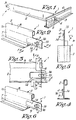
- the fixing essentially consists of a fixing end 1 of at least one profile 2, which can be fitted using a projection 3 of a hook 4 in a slot 5 of a second profile 6.
- the projection 3 forms the extension of a part 7 of the core 8, or possibly of a bead of the first profile 2 and is therefore essentially in the same plane.
- the hook 4 on the projection 3 is a barb formed, for example, by punching cutting.
- At least one of the distances, respectively A and B, between, on the one hand, the free end 9 of the hook 4 and, on the other hand, respectively, the ends of the parts 10 - 11 adjoining the extended part of the core must be greater than the distances, respectively C and D, necessary to put the second profile 6 in place. Consequently there is a clearance 12 and / or 13 between at least one of the two parts 10 - 11 and the profile 6. In the example given there are two clearances (12 and 13).
- the projection 3 can optionally be provided with a stamping 14. Such a stamping stiffens the part 3 and further clamps the profiles 6 in the slots 5
- this stamping may or may not extend to the end 15 of the projection 3.
- Figure 6 shows an alternative embodiment where the tip 15 is straight.
- the invention also makes it possible to mount two profiles, each one being provided with fixing ends 1, on either side of the second profile through a single slot 5, so that these profiles are aligned on a same axis.
- the hook 4 can optionally be provided with a notch 16, which facilitates the fitting of the hook 4 into the slot 5.
Landscapes
- Engineering & Computer Science (AREA)
- Architecture (AREA)
- Physics & Mathematics (AREA)
- Electromagnetism (AREA)
- Civil Engineering (AREA)
- Structural Engineering (AREA)
- Joining Of Building Structures In Genera (AREA)
- Percussive Tools And Related Accessories (AREA)
- Stringed Musical Instruments (AREA)
Description
- Cette invention concerne une fixation pour profilés de plafonds suspendus et plus spécialement un type de fixation entre l'extrémité d'un profilé et l'âme, pourvue de fentes, d'un autre profilé.
- L'invention concerne plus particulièrement une fixation pour profilés en acier galvanisé destinés à constituer la grille de fauxplafonds monolithiques.
- On connaît plusieurs systèmes de fixation pour profilés de plafonds suspendus. Une première construction bien connue consiste à accrocher simplement et sans bloquage les profilés entre eux. Ce système présente l'inconvénient que les profilés se décrochent lorsqu'on les pousse vers le haut. Dans ce cas il est impossible de prévoir des constructions spéciales, telles que des trappes ou dispositifs semblables, sur lesquelles il faut pousser vers le haut, par exemple pour ouvrir et/ou fermer une trappe.
- On connaît également un système où les profilés s'encastrent au moyen de lèvres, qu'il faut plier, afin de former un accrochage fixe. Il est manifeste qu'un tel assemblage demande du doigté et beaucoup de temps.
- On troisième système emploie des pièces d'assemblage reliant les profilés entre eux, ce qui complique la construction
- On connait également, du document AU-B-472 037) une fixation pour profilés de plafonds suspendus avec un premier profilé s'emboîtant au moyen d'une saillie avec crochet dans une des fentes dont est pourvue l'âme du second profilé. La saillie se trouve au bout du premier profilé et forme un prolongement d'une partie de l'âme de ce profile de façon à ce que la saillie se trouve essentiellement dans le même plan que cette âme.
- Tous les systèmes présentent l'inconvénient de ne laisser nulle part assez de jeu pour la dilatation et/ou un assemblage souple des profilés.
- La présente invention prévoit, dans le but d'éliminer les inconvénients cités ainsi que d'autres, un assemblage de profilés pour plafonds suspendus, pouvant être réalisé simplement et rapidement, permettant la dilatation des profilés et ayant une fixation qui ne peut plus être démontée sans outils
- A cette fin, la fixation selon l'invention se compose d'un bout de fixation d'au moins un premier profilé s'emboîtant au moyen d'une saillie, avec crochet à la forme d'un ardillon, dans une des fentes dont est pourvue l'âme du second profilé, dans laquelle ladite saillie se trouve au bout du premier profilé et forme un prolongement d'une partie de l'âme de ce profilé de façon à ce que la saillie se trouve essentiellement dans le même plan que cette âme, caractérisé en ce que au moins une des distances entre, d'une part, l'extrémité libre du crochet et, d'autre part, respectivement, les extrémités jouxtant la partie prolongée du premier profilé, soit plus grande que les distances horizontales correspondantes entre la surface de l'âme verticale du second profilé situées vers le crochet et les parties extrêmes de la section droite du second profilé situées vers le premier profilé, de façon à laisser du jeu entre une des parties nommées en dernier lieu et le second profilé.
- Dans le but de mieux démontrer les caractéristiques de l'invention, suvent, à titre d'exemple et sans aucune intention limitative, deux descriptions de réalisations préférables avec des renvois aux dessins annexées, dans lesquels:
- la figure 1 est un croquis représentant une fixation selon l'invention;
- la figure 2 montre, à plus grande échelle, un bout de fixation d'un profilé selon la figure 1;
- les figures 3, 4 et 5 représentent le bout de fixation vu selon les flèches F3, F4 et F5;
- la figure 6 représente une variante de l'exécution de la figure 2.
- Se référant aux figures 1 à 5, la fixation se compose essentiellement d'un bout de fixation 1 d'au moins un profilé 2, qui peut s'emboîter à l'aide d'une saillie 3 d'un crochet 4 dans une fente 5 d'un second profilé 6.
- La saillie 3 forme le prolongement d'une partie 7 de l'âme 8, ou éventuellement d'un bourrelet du premier profilé 2 et se trouve donc essentiellement dans le même plan.
- Le crochet 4 sur la saillie 3 est un ardillon formé, par exemple, par découpage au poinçonnage. Au moins une des distances, respectivement A et B, entre, d'une part, l'extrémité libre 9 du crochet 4 et, d'autre part, respectivement, les extrémités des parties 10 - 11 jouxtant la partie prolongée de l'âme, doit être plus grande que les distances, respectivement C et D, nécessaires pour mettre le second profilé 6 en place. Par conséquent existe un jeu 12 et/ou 13 entre au moins une des deux parties 10 - 11 et le profilé 6. Dans l'exemple donné il y a deux fois du jeu (12 et 13).
- Dans le cas où il n'y a qu'une fois du jeu, ce qui a pour effet que le profilé ne peut plus se dilater, il vaut mieux garder du jeu en dessous, pour quand même permettre un assemblage souple des profilés 2 et 6.
- La saillie 3 peut être pourvue facultativement d'un emboutissage 14. Un tel emboutissage raidit la partie 3 et serre davantage les profilés 6 dans les fentes 5
- Selon les figures 2 à 6, cet emboutissage peut ou ne peut pas se prolonger jusqu'au bout 15 de la saillie 3. La figure 6 représente une exécution alternative où le bout 15 est rectiligne.
- L'invention permet également de monter deux profilés, chacun étant pourvu de bouts de fixation 1, de part et d'autre du second profilé au travers d'une seule et même fente 5, de façon à ce que ces profilés soient alignés sur un même axe.
- Le crochet 4 peut facultativement être pourvu d'une échancrure 16, qui facilite l'emboîtement du crochet 4 dans la fente 5.
Claims (5)
Priority Applications (3)
| Application Number | Priority Date | Filing Date | Title |
|---|---|---|---|
| DE1985201035 DE205673T1 (de) | 1985-06-28 | 1985-06-28 | Verbindung fuer profile abgehaengter decken. |
| DE8585201035T DE3569593D1 (en) | 1985-06-28 | 1985-06-28 | Joining of profiles for suspended ceilings |
| EP19850201035 EP0205673B1 (fr) | 1985-06-28 | 1985-06-28 | Fixation pour profilés de plafonds suspendus |
Applications Claiming Priority (1)
| Application Number | Priority Date | Filing Date | Title |
|---|---|---|---|
| EP19850201035 EP0205673B1 (fr) | 1985-06-28 | 1985-06-28 | Fixation pour profilés de plafonds suspendus |
Publications (2)
| Publication Number | Publication Date |
|---|---|
| EP0205673A1 EP0205673A1 (fr) | 1986-12-30 |
| EP0205673B1 true EP0205673B1 (fr) | 1989-04-19 |
Family
ID=8194038
Family Applications (1)
| Application Number | Title | Priority Date | Filing Date |
|---|---|---|---|
| EP19850201035 Expired EP0205673B1 (fr) | 1985-06-28 | 1985-06-28 | Fixation pour profilés de plafonds suspendus |
Country Status (2)
| Country | Link |
|---|---|
| EP (1) | EP0205673B1 (fr) |
| DE (2) | DE3569593D1 (fr) |
Families Citing this family (11)
| Publication number | Priority date | Publication date | Assignee | Title |
|---|---|---|---|---|
| US4730433A (en) * | 1986-12-29 | 1988-03-15 | Armstrong World Industries, Inc. | End detail for ceiling runner |
| US4779394B1 (en) * | 1987-04-14 | 1994-09-27 | Donn Inc | Connector for suspension ceiling grid |
| US5044138A (en) * | 1989-10-13 | 1991-09-03 | Usg Interiors, Inc. | Ceiling suspension structure adapted for unopposed intersections |
| US6178712B1 (en) | 1992-04-06 | 2001-01-30 | Worthington Armstrong Venture | Locking connection for ceiling grid system |
| DE4340404C2 (de) * | 1993-11-26 | 2003-02-20 | Worthington Armstrong Venture | Arretierverbindung für ein gitterförmiges Schienensystem einer Hängedecke |
| SE504079C2 (sv) * | 1995-05-03 | 1996-11-04 | Ecophon Ab | Anordning för hopkoppling av profiler |
| US8590275B2 (en) | 2006-06-05 | 2013-11-26 | Worthington Armstrong Venture | Single-layered web beam for a panel suspended ceiling |
| US8590274B2 (en) | 2006-06-05 | 2013-11-26 | Worthington Armstrong Venture | Single-layered web beam for a suspended ceiling |
| US8572930B2 (en) | 2006-06-05 | 2013-11-05 | Worthington Armstrong Venture | Single layered web beam for a drywall suspended ceiling |
| IT1396235B1 (it) * | 2009-05-05 | 2012-11-16 | Antonio Guerrasio S R L | Gancio terminale di bloccaggio per profilati a "t" rovescia atto ad essere inserito e disinserito facilmente in apposite asole senza alcuna deformazione delle parti interessate, grazie ad una linguetta elastica ad esso prevista, priva di bugna. |
| FR3161444A1 (fr) | 2024-04-22 | 2025-10-24 | Marc Funten | Plafond suspendu à démontage sélectif |
Family Cites Families (6)
| Publication number | Priority date | Publication date | Assignee | Title |
|---|---|---|---|---|
| GB1109572A (en) * | 1965-01-21 | 1968-04-10 | Geo Whitehouse & Company Birmi | Improvements relating to suspended ceilings |
| BE680915A (fr) * | 1966-05-12 | 1966-10-17 | ||
| GB1424800A (en) * | 1972-06-26 | 1976-02-11 | Electronic Components Ltd | Structural members and supportin frameworks |
| AU472037B2 (en) * | 1972-09-07 | 1976-05-13 | Rondo Building Services Pty Limited | Improvements in ceiling support runners |
| US3922829A (en) * | 1973-09-14 | 1975-12-02 | Roblin Hope S Ind Inc | Locking connection for supporting grid systems |
| US4531340A (en) * | 1982-08-24 | 1985-07-30 | Donn Incorporated | Beam splice for supporting grid systems |
-
1985
- 1985-06-28 DE DE8585201035T patent/DE3569593D1/de not_active Expired
- 1985-06-28 DE DE1985201035 patent/DE205673T1/de active Pending
- 1985-06-28 EP EP19850201035 patent/EP0205673B1/fr not_active Expired
Also Published As
| Publication number | Publication date |
|---|---|
| DE3569593D1 (en) | 1989-05-24 |
| DE205673T1 (de) | 1987-05-21 |
| EP0205673A1 (fr) | 1986-12-30 |
Similar Documents
| Publication | Publication Date | Title |
|---|---|---|
| EP0205673B1 (fr) | Fixation pour profilés de plafonds suspendus | |
| US5996955A (en) | Engaging member for assembled shelves | |
| FR3002967A3 (fr) | Ensemble de porte de douche | |
| CH631062A5 (fr) | Dispositif d'exposition mural. | |
| EP0669470B1 (fr) | Attache universelle en particulier pour la fixation d'un équipement électrique | |
| FR2720874A1 (fr) | Pièce de suspension pour canalisation électrique. | |
| EP1557572A1 (fr) | Attache pour la fixation de deux pièces l'une sur l'autre | |
| EP1775399B1 (fr) | Revêtement de facade | |
| EP0301658B1 (fr) | Elément de couplage pour faux-plafonds | |
| EP1722111B1 (fr) | Dispositif de fixation destiné à la fixation d'un profilé métallique sur un support | |
| FR2666855A1 (fr) | Dispositif d'assemblage rapide pour constructions modulaires a base de barres. | |
| BE1004086A6 (fr) | Structure de support pour elements de plafonnage. | |
| EP0985834B1 (fr) | Dispositif de fixation d'au moins une pièce sur une autre pièce, en forme de plaque | |
| KR200219599Y1 (ko) | 실톱 | |
| EP0740030B1 (fr) | Attache de fixation d'un panneau sur un élément de structure quelconque | |
| FR2764785A1 (fr) | Dispositif de fixation d'un accotoir de sommier | |
| JP6883321B2 (ja) | 骨格材止め部材 | |
| EP0318371B1 (fr) | Pince élastique à insérer dans un joint pour la fixation automatique et démontable d'objets divers, notamment de couvre-joints | |
| FR2642780A1 (fr) | Dispositif de fixation de panneaux formant par exemple dalles de plafond | |
| JP4359338B2 (ja) | 取付具 | |
| EP0269486B1 (fr) | Elément de structure suspendue comportant des cellules ouvertes situées dans un plan distinct | |
| FR2773832A1 (fr) | Dispositif de connexion d'elements de charpente | |
| FR2572143A1 (fr) | Console amovible pour plaque perforee | |
| WO1984000991A1 (fr) | Organe d'attache | |
| EP0010524A1 (fr) | Paroi de séparation pour le stockage de livres ou de documents |
Legal Events
| Date | Code | Title | Description |
|---|---|---|---|
| PUAI | Public reference made under article 153(3) epc to a published international application that has entered the european phase |
Free format text: ORIGINAL CODE: 0009012 |
|
| 17P | Request for examination filed |
Effective date: 19860424 |
|
| AK | Designated contracting states |
Kind code of ref document: A1 Designated state(s): BE DE FR GB LU NL |
|
| DET | De: translation of patent claims | ||
| 17Q | First examination report despatched |
Effective date: 19870518 |
|
| TCNL | Nl: translation of patent claims filed | ||
| GRAA | (expected) grant |
Free format text: ORIGINAL CODE: 0009210 |
|
| AK | Designated contracting states |
Kind code of ref document: B1 Designated state(s): BE DE FR GB LU NL |
|
| GBT | Gb: translation of ep patent filed (gb section 77(6)(a)/1977) | ||
| REF | Corresponds to: |
Ref document number: 3569593 Country of ref document: DE Date of ref document: 19890524 |
|
| PLBE | No opposition filed within time limit |
Free format text: ORIGINAL CODE: 0009261 |
|
| STAA | Information on the status of an ep patent application or granted ep patent |
Free format text: STATUS: NO OPPOSITION FILED WITHIN TIME LIMIT |
|
| 26N | No opposition filed | ||
| EPTA | Lu: last paid annual fee | ||
| PGFP | Annual fee paid to national office [announced via postgrant information from national office to epo] |
Ref country code: FR Payment date: 19970314 Year of fee payment: 13 |
|
| PGFP | Annual fee paid to national office [announced via postgrant information from national office to epo] |
Ref country code: BE Payment date: 19970318 Year of fee payment: 13 |
|
| PGFP | Annual fee paid to national office [announced via postgrant information from national office to epo] |
Ref country code: DE Payment date: 19970428 Year of fee payment: 13 |
|
| PGFP | Annual fee paid to national office [announced via postgrant information from national office to epo] |
Ref country code: LU Payment date: 19970429 Year of fee payment: 13 |
|
| PGFP | Annual fee paid to national office [announced via postgrant information from national office to epo] |
Ref country code: GB Payment date: 19970627 Year of fee payment: 13 |
|
| PGFP | Annual fee paid to national office [announced via postgrant information from national office to epo] |
Ref country code: NL Payment date: 19970630 Year of fee payment: 13 |
|
| PG25 | Lapsed in a contracting state [announced via postgrant information from national office to epo] |
Ref country code: LU Free format text: LAPSE BECAUSE OF NON-PAYMENT OF DUE FEES Effective date: 19980628 Ref country code: GB Free format text: LAPSE BECAUSE OF NON-PAYMENT OF DUE FEES Effective date: 19980628 |
|
| PG25 | Lapsed in a contracting state [announced via postgrant information from national office to epo] |
Ref country code: BE Free format text: LAPSE BECAUSE OF NON-PAYMENT OF DUE FEES Effective date: 19980630 |
|
| BERE | Be: lapsed |
Owner name: CHICAGO METALLIC CONTINENTAL N.V. Effective date: 19980630 |
|
| PG25 | Lapsed in a contracting state [announced via postgrant information from national office to epo] |
Ref country code: NL Free format text: LAPSE BECAUSE OF NON-PAYMENT OF DUE FEES Effective date: 19990101 |
|
| GBPC | Gb: european patent ceased through non-payment of renewal fee |
Effective date: 19980628 |
|
| PG25 | Lapsed in a contracting state [announced via postgrant information from national office to epo] |
Ref country code: FR Free format text: LAPSE BECAUSE OF NON-PAYMENT OF DUE FEES Effective date: 19990226 |
|
| NLV4 | Nl: lapsed or anulled due to non-payment of the annual fee |
Effective date: 19990101 |
|
| PG25 | Lapsed in a contracting state [announced via postgrant information from national office to epo] |
Ref country code: DE Free format text: LAPSE BECAUSE OF NON-PAYMENT OF DUE FEES Effective date: 19990401 |
|
| REG | Reference to a national code |
Ref country code: FR Ref legal event code: ST |