EP0205394A2 - Verfahren und Vorrichtung zum Positionieren von Gegenständen - Google Patents
Verfahren und Vorrichtung zum Positionieren von Gegenständen Download PDFInfo
- Publication number
- EP0205394A2 EP0205394A2 EP86630100A EP86630100A EP0205394A2 EP 0205394 A2 EP0205394 A2 EP 0205394A2 EP 86630100 A EP86630100 A EP 86630100A EP 86630100 A EP86630100 A EP 86630100A EP 0205394 A2 EP0205394 A2 EP 0205394A2
- Authority
- EP
- European Patent Office
- Prior art keywords
- article
- support
- tray
- platform
- body portion
- Prior art date
- Legal status (The legal status is an assumption and is not a legal conclusion. Google has not performed a legal analysis and makes no representation as to the accuracy of the status listed.)
- Granted
Links
Images
Classifications
-
- B—PERFORMING OPERATIONS; TRANSPORTING
- B65—CONVEYING; PACKING; STORING; HANDLING THIN OR FILAMENTARY MATERIAL
- B65G—TRANSPORT OR STORAGE DEVICES, e.g. CONVEYORS FOR LOADING OR TIPPING, SHOP CONVEYOR SYSTEMS OR PNEUMATIC TUBE CONVEYORS
- B65G61/00—Use of pick-up or transfer devices or of manipulators for stacking or de-stacking articles not otherwise provided for
-
- B—PERFORMING OPERATIONS; TRANSPORTING
- B65—CONVEYING; PACKING; STORING; HANDLING THIN OR FILAMENTARY MATERIAL
- B65G—TRANSPORT OR STORAGE DEVICES, e.g. CONVEYORS FOR LOADING OR TIPPING, SHOP CONVEYOR SYSTEMS OR PNEUMATIC TUBE CONVEYORS
- B65G47/00—Article or material-handling devices associated with conveyors; Methods employing such devices
- B65G47/22—Devices influencing the relative position or the attitude of articles during transit by conveyors
- B65G47/24—Devices influencing the relative position or the attitude of articles during transit by conveyors orientating the articles
Definitions
- the present invention relates to a method and apparatus for positioning articles on a support surface and, more particularly, to a method and apparatus for positioning one or more articles on a support surface, each of which articles has at least one flat end so that the article can stably rest on such flat end.
- the present invention recognizes that past article positioning or orienting devices, such as those described, as well as others known in the art, have been complex in manufacture, operation and maintenance and have been both expensive in cost and in energy and labor consumption. Further, such past devices, because of the physical contact on the article, have often resulted in article bruising or breaking, particularly with those articles which are delicate and readily frangible. Recognizing these past deficiencies, the present invention provides a new and novel method and apparatus for positioning articles in the course of processing which is economical and straightforward in operation and maintenance, requiring a minimum of operating parts and consuming a minimum of energy. Moreover, the unique method and apparatus of the present invention minimizes the often damaging physical contact with the article to be positioned and thus reduces burdensome and costly rejects. Various other features of the present invention will become obvious to one skilled in the art upon reading the disclosure set forth herein.
- the present invention provides a method of positioning an article having opposed ends at least one of which is flat and an irregular surfaced body portion between the ends so that the article can stably rest on the flat end comprising: feeding the article in random orientation to a support surface disposed in a substantially horizontal plane; moving the support surface with the article disposed thereon alternatively in a back-and-forth direction and, simultaneously moving the support surface with the article disposed thereon alternatively in a side-to-side direction so that the resulting forces created by such simultaneous motion of the support surface cause the article to seek a stable- posi-tion and rest on the flat end of the article.
- the present invention provides an apparatus for positioning an article having opposed ends at least one of which is flat and an irregular surfaced body portion between the ends so that the article can stably rest on the flat end
- an article receiving tray the upper surface of which is disposed in a horizontal plane to receive and provide a support surface for the article; a support platform for the tray; bearing means interposed between the tray and platform to permit the tray to move relative the platform; and means to simultaneously move the tray relative the platform in a back-and-forth and side-to-side direction on the bearing means so that the resulting forces created by such simultaneous motion of the tray cause an article fed to the support surface of the tray to seek a stable position to rest on the flat end thereof.
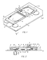
- the inventive apparatus for stably positioning articles having at least one flat end is disclosed as including an article receiving support table 2, the upper surface of which is disposed in a substantially horizontal plane to receive and provide a support surface for carrying trays 5, the articles 4, in turn, being placed in random fashion on support surface 3 of open-ended carrying tray 5.
- articles 4 are disclosed as being in the form of hollow ceramic sleeves of the type used in conjunction with hermetic terminal assemblies.
- each sleeve 4 includes opposed flat ends having intermediate therebetween a hollow cylindrical or irregularly shaped body portion and a hollow truncated cone portion with the body portion having a diameter greater than the overall height of the sleeve.
- the upper surface of table 2 is provided with opposed horseshoe shaped retaining guards 6 at the extremities of support table 2 to retain articles 4 on surface 3 of open-ended carrying trays 5, the articles 4 being fed unto surface 3 of carrying trays 5 in random gravity fashion from the end of pivotally inclined chute 7 positioned in spaced relation above the carrying trays 5 removably mounted on the upper surface of support table 2.
- An intermediate guard rail 8 between guards 6 serves to divide the upper surface of support table 2 into two sections to receive opposed carrying trays 5 which can be readily removed and reversed to further permit easy article loading from pivotable chute 7.
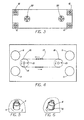
- a support platform 9 is provided below support table 2.
- Platform 9 includes a set (four) of circular wear pads 11 ( Figures 2 and 4) mounted at the corners thereof to each receive one of the bearings of the set (four) of ball bearing casters 12 which are mounted to the lower or under surface of table 2. It is to be understood that various platforms and even a floor could be used to support the table 2. It also is to be understood that the upper surface of support table 2 can slope slightly in a preselected manner to permit collection of articles on carrying trays 5 at a desired location.
- a suitable power source which can be in the form of a variable speed electric motor 13 is mounted relative the platform (below, as shown) with the drive shaft 14 thereof rotatably extending through a suitable aperature in platform 9.
- the shaft 14 of motor 13 engages with a driving gear 16 which in turn connects through drive chain 17 with driven gear 18, both gears being rotatably spaced on platform 9 ( Figures 2 and 4).
- Each gear 16 and 18 is provided with a cam pin 19 which extends in a vertical fashion from the periphery of the gear on which it is mounted.
- a pair of spaced pin receiving members 22 are mounted on the undersurface 23 of table 2.
- the pin receiving members 22, when engaged by pins 19, allow movement of support table 2 in a substantially circular path to provide simultaneous back-and-forth and side-to-side movement of support table 2 and carrying trays 5 mounted thereon.
- pin receiving members 22 are each in the form of a bearing cage.
- the disclosed hollow ceramic sleeves for hermetic terminal assemblies with each sleeve's body portion having a diameter greater than the overall height of the body and truncated cone portion - can be fed in random fashion from pivotal chute 7 positioned above carrying trays 5.
- Trays 5 are supported on table 2 with surface 3 being disposed in a substantially horizontal plane. With the sleeves or articles 4 disposed on trays 5 initially in random fashion, the support table 2 is moved simultaneously in a back-and-forth and side-to-side direction.
- Such simultaneous motion of the support table 2 creates resulting forces which cause the sleeves to seek a more stable position to rest on the surface 3 of carrying trays 5 with the larger ends in faced relation to the support surfaces of the trays for further processing of the sleeves.
- each of the sleeves can be caused to rest through the resulting forces in a confined space or recess 10 in tray 5, the recess 10 confirming with the peripheral shape of the body portion ends.
- the simultaneous motion to create the resulting forces is accomplished by moving the support surfaces in a substantially circular path, it is to be understood that, depending upon such parameters as the shape of the article to be positioned, that other paths -such as eliptical- might also be traced to create the desired simultaneous motion.
Landscapes
- Engineering & Computer Science (AREA)
- Mechanical Engineering (AREA)
- Apparatuses And Processes For Manufacturing Resistors (AREA)
- Specific Conveyance Elements (AREA)
- Radar Systems Or Details Thereof (AREA)
- Auxiliary Devices For And Details Of Packaging Control (AREA)
- Control And Safety Of Cranes (AREA)
- Attitude Control For Articles On Conveyors (AREA)
- Furnace Charging Or Discharging (AREA)
- Feeding Of Articles To Conveyors (AREA)
- Feeding Of Workpieces (AREA)
- Discharge Of Articles From Conveyors (AREA)
- Supplying Of Containers To The Packaging Station (AREA)
Priority Applications (1)
| Application Number | Priority Date | Filing Date | Title |
|---|---|---|---|
| AT86630100T ATE47116T1 (de) | 1985-06-12 | 1986-06-05 | Verfahren und vorrichtung zum positionieren von gegenstaenden. |
Applications Claiming Priority (2)
| Application Number | Priority Date | Filing Date | Title |
|---|---|---|---|
| US06/743,988 US4811831A (en) | 1985-06-12 | 1985-06-12 | Method and apparatus for positioning articles |
| US743988 | 1985-06-12 |
Publications (3)
| Publication Number | Publication Date |
|---|---|
| EP0205394A2 true EP0205394A2 (de) | 1986-12-17 |
| EP0205394A3 EP0205394A3 (en) | 1987-12-23 |
| EP0205394B1 EP0205394B1 (de) | 1989-10-11 |
Family
ID=24990997
Family Applications (1)
| Application Number | Title | Priority Date | Filing Date |
|---|---|---|---|
| EP86630100A Expired EP0205394B1 (de) | 1985-06-12 | 1986-06-05 | Verfahren und Vorrichtung zum Positionieren von Gegenständen |
Country Status (13)
| Country | Link |
|---|---|
| US (1) | US4811831A (de) |
| EP (1) | EP0205394B1 (de) |
| JP (1) | JPS61287620A (de) |
| KR (1) | KR870000225A (de) |
| CN (1) | CN1008268B (de) |
| AT (1) | ATE47116T1 (de) |
| AU (1) | AU580876B2 (de) |
| BR (1) | BR8602716A (de) |
| CA (1) | CA1261781A (de) |
| DE (1) | DE3666212D1 (de) |
| DK (1) | DK274286A (de) |
| ES (1) | ES8800108A1 (de) |
| IL (1) | IL79008A0 (de) |
Families Citing this family (7)
| Publication number | Priority date | Publication date | Assignee | Title |
|---|---|---|---|---|
| US6158952A (en) * | 1994-08-31 | 2000-12-12 | Roberts; Ellis Earl | Oriented synthetic crystal assemblies |
| US5687831A (en) * | 1995-04-25 | 1997-11-18 | Adept Technology, Inc. | Flexible parts feeder |
| US6056108A (en) * | 1997-11-17 | 2000-05-02 | Adept Technology, Inc. | Impulse-based, flexible parts feeder |
| JP3804520B2 (ja) * | 2001-11-27 | 2006-08-02 | 株式会社村田製作所 | チップ部品整列装置 |
| TWI429566B (zh) * | 2012-01-05 | 2014-03-11 | Mas Automation Corp | Automatic Edge Method and Device for Plate - like Material |
| IT201800006994A1 (it) * | 2018-07-06 | 2020-01-06 | Dispositivo ad aspirazione per il trattenimento e/o il trasporto di oggetti di diversi formati | |
| CN112623684B (zh) * | 2019-10-08 | 2022-04-26 | 程玟豪 | 喇叭元件选向装置 |
Family Cites Families (10)
| Publication number | Priority date | Publication date | Assignee | Title |
|---|---|---|---|---|
| US1011444A (en) * | 1909-03-26 | 1911-12-12 | Nat Equip Co | Confectionery machinery. |
| DE487326C (de) * | 1926-10-23 | 1929-12-05 | Hugo Heusch & Cie G M B H | Vorrichtung zum Ordnen von auf ein Schiebebrett aufgeschuetteten Nadeln und Drahtschaeften in parallel neben- und uebereinander liegende Reihen |
| US1720299A (en) * | 1928-05-15 | 1929-07-09 | Albert H Stebbins | Operating means |
| US2232124A (en) * | 1933-11-25 | 1941-02-18 | George E Markley | Mechanically vibrated mechanism |
| US2990935A (en) * | 1954-01-09 | 1961-07-04 | Lamp Presscops Ltd | Apparatus for delivering articles with a predetermined orientation |
| US2863552A (en) * | 1954-01-09 | 1958-12-09 | Lamp Presscaps Ltd | Apparatus for delivering articles with a predetermined orientation |
| US2990934A (en) * | 1958-07-21 | 1961-07-04 | Ex Cell O Corp | Mechanism for pairing containers having gabled top enclosed pouring spout |
| US3504783A (en) * | 1968-12-09 | 1970-04-07 | August Kuschnereit | Method and apparatus for separating tangled,coiled helixes |
| US3756407A (en) * | 1970-08-31 | 1973-09-04 | Black Clawson Co | Vibratory screening with a peripheral support base |
| US4402108A (en) * | 1981-02-17 | 1983-09-06 | Pannwitz Hans U | Reduced static castor |
-
1985
- 1985-06-12 US US06/743,988 patent/US4811831A/en not_active Expired - Fee Related
-
1986
- 1986-04-21 CA CA000507162A patent/CA1261781A/en not_active Expired
- 1986-06-03 IL IL79008A patent/IL79008A0/xx unknown
- 1986-06-05 EP EP86630100A patent/EP0205394B1/de not_active Expired
- 1986-06-05 AT AT86630100T patent/ATE47116T1/de not_active IP Right Cessation
- 1986-06-05 DE DE8686630100T patent/DE3666212D1/de not_active Expired
- 1986-06-09 JP JP61133608A patent/JPS61287620A/ja active Pending
- 1986-06-11 BR BR8602716A patent/BR8602716A/pt unknown
- 1986-06-11 AU AU58525/86A patent/AU580876B2/en not_active Ceased
- 1986-06-11 ES ES555937A patent/ES8800108A1/es not_active Expired
- 1986-06-11 DK DK274286A patent/DK274286A/da not_active Application Discontinuation
- 1986-06-12 CN CN86104337A patent/CN1008268B/zh not_active Expired
- 1986-06-12 KR KR1019860004680A patent/KR870000225A/ko not_active Withdrawn
Also Published As
| Publication number | Publication date |
|---|---|
| CN86104337A (zh) | 1987-03-11 |
| BR8602716A (pt) | 1987-02-10 |
| US4811831A (en) | 1989-03-14 |
| DK274286A (da) | 1986-12-13 |
| ATE47116T1 (de) | 1989-10-15 |
| DK274286D0 (da) | 1986-06-11 |
| AU5852586A (en) | 1986-12-18 |
| DE3666212D1 (en) | 1989-11-16 |
| CN1008268B (zh) | 1990-06-06 |
| JPS61287620A (ja) | 1986-12-18 |
| ES8800108A1 (es) | 1987-10-16 |
| CA1261781A (en) | 1989-09-26 |
| ES555937A0 (es) | 1987-10-16 |
| EP0205394A3 (en) | 1987-12-23 |
| IL79008A0 (en) | 1986-09-30 |
| KR870000225A (ko) | 1987-02-17 |
| EP0205394B1 (de) | 1989-10-11 |
| AU580876B2 (en) | 1989-02-02 |
Similar Documents
| Publication | Publication Date | Title |
|---|---|---|
| US4658947A (en) | Transfer mechanism | |
| CA2085152C (en) | Device destined to handle and orientate flat workpieces arranged in batches | |
| KR960006832B1 (ko) | 절단기에서의 공작물 이송방법 및 장치 | |
| NZ215843A (en) | Conveyor system: chain conveyor lifted into contact with articles by inflatable bags | |
| US6978879B2 (en) | 360 degree rotatable lifter arm for log singulator | |
| US4811831A (en) | Method and apparatus for positioning articles | |
| CZ291260B6 (cs) | Zařízení pro závěsnou dopravu ploąných dílců, jako plechů, plechových výrobků a podobného plochého zboľí, pracující se sacím vzduchem | |
| US6116842A (en) | Transfer car for a conveyor system | |
| EP0512585A1 (de) | Eierorientierungsvorrichtung | |
| US4413941A (en) | Machine tool support table and feeding device | |
| DE68909967D1 (de) | Vorrichtung zum Biegen von Teigstücken. | |
| US2637433A (en) | Container handling conveyer | |
| JPH0659931B2 (ja) | 鶏卵等の被処理物の移替装置 | |
| EP0801629B1 (de) | Vorrichtung und verfahren um gegenstände aus einem stapel zu entnehmen | |
| CN213833532U (zh) | 一种顶升移栽机设备 | |
| AU581053B2 (en) | Helical storage container | |
| CN112193793A (zh) | 一种顶升移栽机设备 | |
| DE3763060D1 (de) | Magazinier-system. | |
| JP2000142614A (ja) | 物品箱詰め装置 | |
| CN217837384U (zh) | 用于轴件自动上下料的装置 | |
| CN223356676U (zh) | 一种整理载具内物品的设备 | |
| CN222158564U (zh) | 一种立式输送机 | |
| JP2675308B2 (ja) | ワーク仕分け集積装置 | |
| CN212019289U (zh) | 一种自动送料的摩擦压力机 | |
| JPH0444482Y2 (de) |
Legal Events
| Date | Code | Title | Description |
|---|---|---|---|
| PUAI | Public reference made under article 153(3) epc to a published international application that has entered the european phase |
Free format text: ORIGINAL CODE: 0009012 |
|
| AK | Designated contracting states |
Kind code of ref document: A2 Designated state(s): AT CH DE FR GB IT LI NL |
|
| PUAL | Search report despatched |
Free format text: ORIGINAL CODE: 0009013 |
|
| AK | Designated contracting states |
Kind code of ref document: A3 Designated state(s): AT CH DE FR GB IT LI NL |
|
| 17P | Request for examination filed |
Effective date: 19880217 |
|
| 17Q | First examination report despatched |
Effective date: 19880607 |
|
| GRAA | (expected) grant |
Free format text: ORIGINAL CODE: 0009210 |
|
| AK | Designated contracting states |
Kind code of ref document: B1 Designated state(s): AT CH DE FR GB IT LI NL |
|
| REF | Corresponds to: |
Ref document number: 47116 Country of ref document: AT Date of ref document: 19891015 Kind code of ref document: T |
|
| ET | Fr: translation filed | ||
| REF | Corresponds to: |
Ref document number: 3666212 Country of ref document: DE Date of ref document: 19891116 |
|
| ITF | It: translation for a ep patent filed | ||
| PG25 | Lapsed in a contracting state [announced via postgrant information from national office to epo] |
Ref country code: GB Effective date: 19900605 Ref country code: AT Effective date: 19900605 |
|
| PG25 | Lapsed in a contracting state [announced via postgrant information from national office to epo] |
Ref country code: LI Effective date: 19900630 Ref country code: CH Effective date: 19900630 |
|
| PLBE | No opposition filed within time limit |
Free format text: ORIGINAL CODE: 0009261 |
|
| STAA | Information on the status of an ep patent application or granted ep patent |
Free format text: STATUS: NO OPPOSITION FILED WITHIN TIME LIMIT |
|
| 26N | No opposition filed | ||
| PG25 | Lapsed in a contracting state [announced via postgrant information from national office to epo] |
Ref country code: NL Effective date: 19910101 |
|
| GBPC | Gb: european patent ceased through non-payment of renewal fee | ||
| NLV4 | Nl: lapsed or anulled due to non-payment of the annual fee | ||
| PG25 | Lapsed in a contracting state [announced via postgrant information from national office to epo] |
Ref country code: FR Effective date: 19910228 |
|
| REG | Reference to a national code |
Ref country code: CH Ref legal event code: PL |
|
| PG25 | Lapsed in a contracting state [announced via postgrant information from national office to epo] |
Ref country code: DE Effective date: 19910301 |
|
| REG | Reference to a national code |
Ref country code: FR Ref legal event code: ST |
|
| PG25 | Lapsed in a contracting state [announced via postgrant information from national office to epo] |
Ref country code: IT Free format text: LAPSE BECAUSE OF NON-PAYMENT OF DUE FEES;WARNING: LAPSES OF ITALIAN PATENTS WITH EFFECTIVE DATE BEFORE 2007 MAY HAVE OCCURRED AT ANY TIME BEFORE 2007. THE CORRECT EFFECTIVE DATE MAY BE DIFFERENT FROM THE ONE RECORDED. Effective date: 20050605 |