EP0205367A1 - Unter Druck ausdehnbare Vorrichtung mit selbstklemmender Anordnung von Verstärkungslagen zum Verschliessen von Leitungen - Google Patents
Unter Druck ausdehnbare Vorrichtung mit selbstklemmender Anordnung von Verstärkungslagen zum Verschliessen von Leitungen Download PDFInfo
- Publication number
- EP0205367A1 EP0205367A1 EP86401029A EP86401029A EP0205367A1 EP 0205367 A1 EP0205367 A1 EP 0205367A1 EP 86401029 A EP86401029 A EP 86401029A EP 86401029 A EP86401029 A EP 86401029A EP 0205367 A1 EP0205367 A1 EP 0205367A1
- Authority
- EP
- European Patent Office
- Prior art keywords
- plies
- corner
- hooping
- support element
- clamping
- Prior art date
- Legal status (The legal status is an assumption and is not a legal conclusion. Google has not performed a legal analysis and makes no representation as to the accuracy of the status listed.)
- Granted
Links
- 230000002787 reinforcement Effects 0.000 claims abstract description 11
- 230000003014 reinforcing effect Effects 0.000 claims abstract description 11
- 230000001464 adherent effect Effects 0.000 claims abstract description 3
- 239000000463 material Substances 0.000 claims description 3
- 239000011248 coating agent Substances 0.000 claims 1
- 238000000576 coating method Methods 0.000 claims 1
- 238000004804 winding Methods 0.000 claims 1
- 230000000694 effects Effects 0.000 description 10
- 229920001971 elastomer Polymers 0.000 description 5
- 238000000034 method Methods 0.000 description 3
- 238000010494 dissociation reaction Methods 0.000 description 2
- 230000005593 dissociations Effects 0.000 description 2
- 239000012530 fluid Substances 0.000 description 2
- 239000000443 aerosol Substances 0.000 description 1
- 238000004873 anchoring Methods 0.000 description 1
- 238000006243 chemical reaction Methods 0.000 description 1
- 230000008602 contraction Effects 0.000 description 1
- 238000002788 crimping Methods 0.000 description 1
- 239000000806 elastomer Substances 0.000 description 1
- 238000005516 engineering process Methods 0.000 description 1
- 238000003780 insertion Methods 0.000 description 1
- 230000037431 insertion Effects 0.000 description 1
- 238000003754 machining Methods 0.000 description 1
- 238000012986 modification Methods 0.000 description 1
- 230000004048 modification Effects 0.000 description 1
- 230000007935 neutral effect Effects 0.000 description 1
- 230000035515 penetration Effects 0.000 description 1
- 239000003208 petroleum Substances 0.000 description 1
- 239000004810 polytetrafluoroethylene Substances 0.000 description 1
- 229920001343 polytetrafluoroethylene Polymers 0.000 description 1
- 238000007789 sealing Methods 0.000 description 1
- 238000000926 separation method Methods 0.000 description 1
Images
Classifications
-
- F—MECHANICAL ENGINEERING; LIGHTING; HEATING; WEAPONS; BLASTING
- F16—ENGINEERING ELEMENTS AND UNITS; GENERAL MEASURES FOR PRODUCING AND MAINTAINING EFFECTIVE FUNCTIONING OF MACHINES OR INSTALLATIONS; THERMAL INSULATION IN GENERAL
- F16L—PIPES; JOINTS OR FITTINGS FOR PIPES; SUPPORTS FOR PIPES, CABLES OR PROTECTIVE TUBING; MEANS FOR THERMAL INSULATION IN GENERAL
- F16L37/00—Couplings of the quick-acting type
- F16L37/02—Couplings of the quick-acting type in which the connection is maintained only by friction of the parts being joined
- F16L37/04—Couplings of the quick-acting type in which the connection is maintained only by friction of the parts being joined with an elastic outer part pressing against an inner part by reason of its elasticity
- F16L37/06—Couplings of the quick-acting type in which the connection is maintained only by friction of the parts being joined with an elastic outer part pressing against an inner part by reason of its elasticity tightened by fluid pressure
-
- E—FIXED CONSTRUCTIONS
- E21—EARTH OR ROCK DRILLING; MINING
- E21B—EARTH OR ROCK DRILLING; OBTAINING OIL, GAS, WATER, SOLUBLE OR MELTABLE MATERIALS OR A SLURRY OF MINERALS FROM WELLS
- E21B33/00—Sealing or packing boreholes or wells
- E21B33/10—Sealing or packing boreholes or wells in the borehole
- E21B33/12—Packers; Plugs
- E21B33/127—Packers; Plugs with inflatable sleeve
- E21B33/1277—Packers; Plugs with inflatable sleeve characterised by the construction or fixation of the sleeve
-
- F—MECHANICAL ENGINEERING; LIGHTING; HEATING; WEAPONS; BLASTING
- F16—ENGINEERING ELEMENTS AND UNITS; GENERAL MEASURES FOR PRODUCING AND MAINTAINING EFFECTIVE FUNCTIONING OF MACHINES OR INSTALLATIONS; THERMAL INSULATION IN GENERAL
- F16K—VALVES; TAPS; COCKS; ACTUATING-FLOATS; DEVICES FOR VENTING OR AERATING
- F16K7/00—Diaphragm valves or cut-off apparatus, e.g. with a member deformed, but not moved bodily, to close the passage ; Pinch valves
- F16K7/10—Diaphragm valves or cut-off apparatus, e.g. with a member deformed, but not moved bodily, to close the passage ; Pinch valves with inflatable member
Definitions
- the main patent describes a flexible, expandable hose device for use in areas where very high performance is required. This is, in particular, the case of plugs for boreholes, petroleum or other, where the fluids are at high pressure (for example 350 bar) and at high temperature (for example 120 ° C.).
- the shutter systems using the properties of expandable pipes are well known and commonly used; they exist in various forms, for diameters as different as 50 mm or 800 mm.
- the objective of the invention is to make it possible to considerably increase the performance of expandable shutters, prohibiting the separation of the armature, consisting of the reinforcing elements of the pipe, from the parts. which are essential to allow the implementation of the principle of obturation by expansion of the pipe.
- connection QL is defined as the ratio between the force F which it is necessary to apply to dissociate the reinforcement from the end pieces and the tensile strength R of the reinforcement.
- the link quality QL F / R therefore defines a link efficiency; for example, a connection will be considered of poor quality when, for an intrinsic resistance of the reinforcement R of 100 daN, there will be dissociation between the reinforcement and the end piece for a force F of 60 daN ; the link efficiency will then be 0.60. Conversely, good link quality will be achieved when the yield is, in all circumstances, close to 1 or equal to 1.
- the device, object of the invention makes it possible to avoid the phenomena of tearing off, taking off or sliding which result from the use of the devices of the prior art.
- a solution for large diameter pipes is the subject of the main patent; it is mainly adapted to diameters greater than 300 mm, the average diameter considered at the level of the reinforcements.
- the solution consists in providing a flexible pipe device in which the ends are secured in an extremely resistant manner to the rigid end pieces, so that the assembly can withstand forces. very important, especially at very high pressures and temperatures.
- the invention described aims to provide a device in which the hose is expandable to serve for closing the pipes of boreholes and similar applications, in which the method of fixing the hose to the rigid end pieces is made without exceeding the outside diameter of the pipe, in order to make full use of the expansion capacity of said pipe.
- At least one end of the pipe is fixed, by tightening its reinforcing plies, between an internal support element and an external hooping element, co-axial, characterized in that the internal element of support and the outer hooping element have conical, co-axial surfaces, divergent towards the end of the device, and in that at least one corner is pressed between the ends of the reinforcing plies to clamp them respectively between the (s) said corner (s) and the support and anchoring elements.
- This arrangement differs from the system described in the main patent in that it uses one (or more) cone (s) distributed at the rate of 1 cone for a pair of plies alternately right and left. It makes it possible to obtain an excellent fixing of the end of the pipe because, under the effect of the operating pressure, the tension forces exerted on the reinforcement plies of the pipe tend to push in the corner (s) ) between said surfaces of tightening and self-tightening effect of these plies, both against the surfaces of the (or) corner (s) adjacent (s) and the surfaces of the inner support and hooping elements.
- the angle at the top of the section of a corner has a small value, of the order of 5 to 15 °, distributed on either side of the cylindrical surface passing through the top of the corner.
- This arrangement allows, in particular, to give the rigid parts a sufficient section while maintaining their diameter at a value equal to or slightly greater than that of the diameter of the body of the pipe.
- All of these means act jointly to make the self-tightening effect operate, in proportion to the tension force exerted by the reinforcing plies as soon as the commissioning requests the reinforcement under the effect of the pressure. .
- the non-adhesion of said elements allows tightening, which is automatically distributed and balanced.
- the slits in the corner (s) make it possible for the said corner (s) to contract or expand.
- FIGS. 1 to 5 Other characteristics and advantages of the invention will emerge from the detailed description of an exemplary embodiment illustrated by FIGS. 1 to 5.
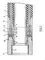
- the device illustrated in FIG. 1 essentially comprises a tubular sleeve (1), made of rubber, fixed at each end to a rigid assembly (2) comprising fixing means such as the thread (3) on a piece for closing off the 'set (not shown), or any other means extending the device object of the invention, to participate in its implementation.
- the wall of the rubber sleeve (1) is reinforced by pairs of plies (4) already described in the main patent.
- the tubular sleeve (1) is fixed to the rigid assembly (2) forming the end of the device.
- the ends (4.1), (4.2), (4.3) and (4.4) of the plies or pairs of plies (4) are engaged in the conical annular space comprised between the support elements (5) and co-axial hooping element (6), the support element (5) and the hooping element (6) having facing clamping surfaces which limit the conical space diverging towards the ends of the plies (4).
- a third rigid element (7) and a fourth rigid element (8) in the form of a wedge, are driven axially, respectively between the ends (4.3) and (4.4) and the ends (4.1) and (4.2). pairs of reinforcing plies (4), so as to clamp these ends respectively against the support element (5) and the hooping element (6) by bearing, one on the other, by the 'intermediate ends (4.2) and - (4.3) clamped one on the other in the central part of the conical space between the support element (5) and the hooping element (6).
- corner clamping surfaces such as, for example, the corner clamping surfaces (7) with the plies (4.3) and (4.4) could have notches, ribs or asperities capable of increasing the adhesion and the attachment of the sheets to these surfaces.
- the clamping surface between the support element (5) and the end (4.4) of the frame (4) on the one hand, and the clamping surface between between the hooping element (6) and the end (4.1) of the frame (4) on the other hand are made non-adherent with respect to materials such as, for example, the rubber with which the plies (4) of the frame are impregnated .
- any tensile force exerted on the armature (4) tends to drive the corners (7) and (8) in the direction of their insertion between the 'support element (5) and the hooping element (6) and to produce, thus, a self-tightening of the ends (4.1), (4.2) (4.3) and (4.4) of the plies of reinforcement between the corresponding conical surfaces.
- This self-tightening is considerably improved by the non-adhesion of the conical surfaces belonging to the support element (5) and to the hooping element (6) which are made integral with the end piece (2) by connecting means such as threads (9) and (10).
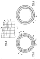
- FIGS. 2, 3, and 4 an arrangement with two pairs of plies and two co-axial corners conforms to the description of FIGS. 2, 3, and 4 in which FIG. 2 is a partial representation of a corner seen by its external lateral face.
- Figure 3 completes this description with a section aa of the arrangement of Figure 2, in the neutral position, as it is produced, for example, when mounting the device.
- the balancing slots, such as (11) and (12) are distributed in pairs, offset by 120 ° for example, such as the pairs (11) and (12), (13) and (14) or (15 ) and (16) on the corner (7).
- Each pair of slots, such as (11) and (12) is produced by machining the cone, one slot being offset relative to the other, in position and in depth, so as to leave a peduncle of material (17) between said slots, the length and section of which are chosen so as to allow a deformation resulting from the widening or narrowing of the slots during the positioning of the cones or their reaction when the element between support and hooping element.
- the practical width of the slits is between 1 and 3 mm, the sum of the depths of the slits of a pair being preferably 5 to 10 mm greater than the length represented by the normal distance between the top and the base of the cone.
- the section of the peduncle (17) is between 20 and 50 mm2.
- a set of two corners is mounted so as to offset the pairs of slots in the interior corner with respect to the couples of slots in the exterior corner by a half angle defining the angular spacing of the pairs of slots in the interior corner; this avoids the risk of overlapping the pairs of slots of two or more coaxial corners.
- Figure 4 shows the respective positions of section a-a of two corners such as (7) and (8), after balancing the clamping between the support and hooping elements.
- the wedge slots (7) are closed, which, by reducing the circumference of the wedge section, is equivalent to an axial contraction of said wedge.
- the wedge (8) is biased, for example, in expansion, which corresponds to a radial expansion and to a spacing of the balancing slots.
- This arrangement provides an important advantage under the effect of a repercussion of the tightening effect on the sheets which are inserted in the space (18) between the two corners (7) and - (8).
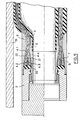
- FIG. 5 represents, on the half lower section, a device according to the invention, with two corners, in the rest state and, on the upper half-section, the same device, in the working position, in the inflated state, closing off a pipe (19) .
- the corners (7) and (8) are notched to improve their attachment to the plies and guarantee their perfect training by the latter, under the effect of a stress due to the pressure.
- the space (20) between the ends of the plies (4.1) to (4.4), the base of the corners (7) and (8) and the end piece (2) is filled with an filling elastomer ensuring perfect sealing of the device against possible penetration of fluid entering the layers - (4.1) to (4.4) and the corners (7) and (8).
- the conical clamping surfaces (21) of the support element (5) and (22) of the hooping element (6) have been coated, before assembly, with a non-stick product, such that, at as a non-limiting example, PTFE aerosol.
- the corners (7) and (8), co-axial, have symmetrical sections with respect to the cylindrical surface defined between the plies (4.2) and (4.3) such that the total angle at the top is close to 20 °.
Landscapes
- Engineering & Computer Science (AREA)
- General Engineering & Computer Science (AREA)
- Mining & Mineral Resources (AREA)
- Physics & Mathematics (AREA)
- Mechanical Engineering (AREA)
- Life Sciences & Earth Sciences (AREA)
- Fluid Mechanics (AREA)
- Geology (AREA)
- General Life Sciences & Earth Sciences (AREA)
- Environmental & Geological Engineering (AREA)
- Geochemistry & Mineralogy (AREA)
- Rigid Pipes And Flexible Pipes (AREA)
- Joints That Cut Off Fluids, And Hose Joints (AREA)
- Pipe Accessories (AREA)
- Mutual Connection Of Rods And Tubes (AREA)
- Clamps And Clips (AREA)
Applications Claiming Priority (2)
| Application Number | Priority Date | Filing Date | Title |
|---|---|---|---|
| FR8507473 | 1985-05-14 | ||
| FR8507473A FR2582077B2 (fr) | 1985-05-14 | 1985-05-14 | Perfectionnement a un dispositif a tuyau dilatable |
Publications (2)
| Publication Number | Publication Date |
|---|---|
| EP0205367A1 true EP0205367A1 (de) | 1986-12-17 |
| EP0205367B1 EP0205367B1 (de) | 1989-05-03 |
Family
ID=9319364
Family Applications (1)
| Application Number | Title | Priority Date | Filing Date |
|---|---|---|---|
| EP86401029A Expired EP0205367B1 (de) | 1985-05-14 | 1986-05-14 | Unter Druck ausdehnbare Vorrichtung mit selbstklemmender Anordnung von Verstärkungslagen zum Verschliessen von Leitungen |
Country Status (6)
| Country | Link |
|---|---|
| US (1) | US4895185A (de) |
| EP (1) | EP0205367B1 (de) |
| JP (1) | JPH0621675B2 (de) |
| CA (1) | CA1300047C (de) |
| DE (1) | DE3663186D1 (de) |
| FR (1) | FR2582077B2 (de) |
Cited By (2)
| Publication number | Priority date | Publication date | Assignee | Title |
|---|---|---|---|---|
| US4886117A (en) * | 1986-10-24 | 1989-12-12 | Schlumberger Technology Corporation | Inflatable well packers |
| US5924894A (en) * | 1995-11-13 | 1999-07-20 | Radiall | Signal processing circuit |
Families Citing this family (33)
| Publication number | Priority date | Publication date | Assignee | Title |
|---|---|---|---|---|
| EP0265341B1 (de) * | 1986-10-24 | 1994-06-15 | Schlumberger Technology Corporation | Aufblasbarer Packer für Bohrlöcher |
| US5526846A (en) * | 1990-12-26 | 1996-06-18 | Coflexip | Stiffener with reinforced structure |
| FR2683260B1 (fr) * | 1991-11-05 | 1995-10-20 | Aerospatiale | Tube en materiau composite pour forage et/ou transport de produits liquides ou gazeux, en particulier pour l'exploitation petroliere en mer et procede de fabrication d'un tel tube. |
| US5353842A (en) * | 1992-02-20 | 1994-10-11 | Lundman Philip L | Inflatable plug for use in plugging a large diameter pipe |
| US5390738A (en) * | 1992-11-25 | 1995-02-21 | Dowell Schlumberger Incorporated | Inflatable packer inner bladder retention and seal |
| FR2743614B1 (fr) * | 1996-01-11 | 1998-02-13 | Coflexip | Canalisation flexible |
| ATE206794T1 (de) * | 1997-08-26 | 2001-10-15 | Stresshead Ag | Verstärkungsvorrichtung für tragstrukturen |
| HU218344B (hu) * | 1997-09-23 | 2000-08-28 | TAURUS EMERGÉ Gumiipari Kft. | Nagynyomású hajlékony tömlőszerkezet, és eljárás annak előállítására |
| DE69715474D1 (de) * | 1997-10-14 | 2002-10-17 | Nkt Flexibles I S Brondby | Flexible rohrleitung mit einem zugeordneten anschlussteil |
| US5901752A (en) * | 1998-06-05 | 1999-05-11 | Lundman; Philip L. | Inflatable apparatus for sealing a pipeline |
| AU5522700A (en) | 1999-07-23 | 2001-02-13 | Nkt Flexibles I/S | A method of securing reinforcement wires to an end termination of a pipeline or a cable, an end termination, and uses of the method and the end termination |
| FR2816389B1 (fr) * | 2000-11-08 | 2003-05-30 | Coflexip | Embout pour conduite flexible |
| US6446669B1 (en) | 2001-01-04 | 2002-09-10 | Philip L. Lundman | Pipe sealing apparatus |
| DE60208675D1 (de) * | 2001-05-02 | 2006-04-06 | Shell Int Research | Bohrloch mit flexiblen förderrohren |
| FR2906595B1 (fr) * | 2006-09-29 | 2010-09-17 | Technip France | Embout de fixation de conduite tubulaire flexible a hautes resistances |
| US7455077B2 (en) * | 2007-01-10 | 2008-11-25 | Lundman Philip L | Inflatable plug with flange |
| US20090160184A1 (en) * | 2007-12-20 | 2009-06-25 | Vo Dang The | End Connector For Flexible Pipe |
| US8276620B2 (en) * | 2008-03-05 | 2012-10-02 | Vo Dang The | Flexible pipe for offshore and other applications |
| US7946313B2 (en) | 2008-03-05 | 2011-05-24 | Vo Dang The | Flexible pipe |
| FR2931920B1 (fr) * | 2008-06-02 | 2010-09-17 | Saltel Ind | Conduite flexible a embouts d'extremite integres |
| DE102011105715A1 (de) * | 2011-06-23 | 2012-12-27 | De-Sta-Co Europe Gmbh | Verbindungsanordnung |
| US8757213B2 (en) | 2011-11-04 | 2014-06-24 | Blue Gentian, Llc | Commercial hose |
| US8291942B2 (en) | 2011-11-04 | 2012-10-23 | Blue Gentian, Llc | Expandable hose assembly |
| US8291941B1 (en) | 2011-11-04 | 2012-10-23 | Blue Gentian, Llc | Expandable and contractible hose |
| US10174870B2 (en) | 2011-11-04 | 2019-01-08 | Telebrands Corp. | Expandable and contractible garden hose |
| US8479776B2 (en) | 2011-11-04 | 2013-07-09 | Blue Gentian, Llc | Expandable garden hose |
| WO2014169057A1 (en) * | 2013-04-09 | 2014-10-16 | Blue Gentian, Llc | Automatically expandable hose |
| US10094493B2 (en) | 2013-11-29 | 2018-10-09 | Don Disbrow | Expandable air hose |
| DE112016006572B4 (de) | 2016-03-10 | 2023-10-05 | Donald Disbrow | Verfahren zum Bereitstellen von Druckluft von einem Kompressor zu einem Arbeitswerkzeug |
| US11066913B2 (en) * | 2016-05-01 | 2021-07-20 | Cameron International Corporation | Flexible fracturing line with removable liner |
| CN108799645B (zh) * | 2018-09-01 | 2024-07-26 | 湛江市霞山信佳橡塑制品有限公司 | 一种四层结构的通水装置 |
| US10935171B1 (en) * | 2019-09-30 | 2021-03-02 | Tofle Co., Inc. | Connecting mechanism and tube assembly |
| DE102019219958B4 (de) | 2019-12-18 | 2023-10-05 | Zf Friedrichshafen Ag | Verfahren zur Schaltsteuerung eines automatisierten Schaltgetriebes |
Citations (6)
| Publication number | Priority date | Publication date | Assignee | Title |
|---|---|---|---|---|
| US2643722A (en) * | 1948-02-26 | 1953-06-30 | Lynes Inc | Hydraulically inflatable packer |
| GB954051A (en) * | 1959-11-25 | 1964-04-02 | Oil Feed Engineering Company L | A new or improved end fitting for flexible hose |
| US3437142A (en) * | 1965-10-28 | 1969-04-08 | George E Conover | Inflatable packer for external use on casing and liners and method of use |
| US3542127A (en) * | 1968-05-13 | 1970-11-24 | Lynes Inc | Reinforced inflatable packer with expansible back-up skirts for end portions |
| FR2334045A1 (fr) * | 1975-12-02 | 1977-07-01 | Goodyear Tire & Rubber | Bride d'extremite pour tuyaux souples et procede de pose d'une telle bride |
| EP0080918A1 (de) * | 1981-11-20 | 1983-06-08 | Caoutchouc Manufacturé et Plastiques Société Anonyme dite: | Absperrorgan für Leitungen |
Family Cites Families (4)
| Publication number | Priority date | Publication date | Assignee | Title |
|---|---|---|---|---|
| US2273398A (en) * | 1941-05-02 | 1942-02-17 | Flex O Tube Company | Flexible hose coupling |
| US3834965A (en) * | 1969-01-29 | 1974-09-10 | Gen Electric | Method of making a lightweight duct |
| US4234019A (en) * | 1979-01-12 | 1980-11-18 | The Goodyear Tire & Rubber Company | Lug bead hose |
| HU183563B (en) * | 1981-09-03 | 1984-05-28 | Taurus Gumiipari Vallalat | High-pressure hose suitable for carrying gases and gas-containing fluids |
-
1985
- 1985-05-14 FR FR8507473A patent/FR2582077B2/fr not_active Expired
-
1986
- 1986-04-28 CA CA000507737A patent/CA1300047C/fr not_active Expired - Lifetime
- 1986-05-13 JP JP61109332A patent/JPH0621675B2/ja not_active Expired - Lifetime
- 1986-05-14 EP EP86401029A patent/EP0205367B1/de not_active Expired
- 1986-05-14 DE DE8686401029T patent/DE3663186D1/de not_active Expired
-
1988
- 1988-01-14 US US07/143,958 patent/US4895185A/en not_active Expired - Lifetime
Patent Citations (6)
| Publication number | Priority date | Publication date | Assignee | Title |
|---|---|---|---|---|
| US2643722A (en) * | 1948-02-26 | 1953-06-30 | Lynes Inc | Hydraulically inflatable packer |
| GB954051A (en) * | 1959-11-25 | 1964-04-02 | Oil Feed Engineering Company L | A new or improved end fitting for flexible hose |
| US3437142A (en) * | 1965-10-28 | 1969-04-08 | George E Conover | Inflatable packer for external use on casing and liners and method of use |
| US3542127A (en) * | 1968-05-13 | 1970-11-24 | Lynes Inc | Reinforced inflatable packer with expansible back-up skirts for end portions |
| FR2334045A1 (fr) * | 1975-12-02 | 1977-07-01 | Goodyear Tire & Rubber | Bride d'extremite pour tuyaux souples et procede de pose d'une telle bride |
| EP0080918A1 (de) * | 1981-11-20 | 1983-06-08 | Caoutchouc Manufacturé et Plastiques Société Anonyme dite: | Absperrorgan für Leitungen |
Cited By (2)
| Publication number | Priority date | Publication date | Assignee | Title |
|---|---|---|---|---|
| US4886117A (en) * | 1986-10-24 | 1989-12-12 | Schlumberger Technology Corporation | Inflatable well packers |
| US5924894A (en) * | 1995-11-13 | 1999-07-20 | Radiall | Signal processing circuit |
Also Published As
| Publication number | Publication date |
|---|---|
| US4895185A (en) | 1990-01-23 |
| FR2582077B2 (fr) | 1987-12-24 |
| DE3663186D1 (en) | 1989-06-08 |
| EP0205367B1 (de) | 1989-05-03 |
| JPH0621675B2 (ja) | 1994-03-23 |
| FR2582077A2 (fr) | 1986-11-21 |
| JPS61262270A (ja) | 1986-11-20 |
| CA1300047C (fr) | 1992-05-05 |
Similar Documents
| Publication | Publication Date | Title |
|---|---|---|
| EP0205367B1 (de) | Unter Druck ausdehnbare Vorrichtung mit selbstklemmender Anordnung von Verstärkungslagen zum Verschliessen von Leitungen | |
| EP0080918B1 (de) | Absperrorgan für Leitungen | |
| EP1066450B1 (de) | Metallrohrschraubverbindung zur enthaltung einer korrodierenden flüssigkeit | |
| EP0867596B1 (de) | Gewindeverbinder für Rohre | |
| EP3014157B1 (de) | Schlauch und verfahren dafür | |
| FR2875286A1 (fr) | Dispositif d'etancheite servant a obturer un puits ou une canalisation | |
| FR3074251A1 (fr) | Embout de connexion d'une conduite flexible de transport de fluide, conduite et procede associes | |
| FR2844331A1 (fr) | Procede de realisation d'un joint tubulaire etanche avec expansion plastique | |
| FR2727738A1 (fr) | Conduite tubulaire flexible comportant une nappe d'armure agrafee | |
| WO1998041729A1 (fr) | Dispositif limiteur de courbure d'une conduite flexible | |
| FR2889727A1 (fr) | Joint filete tubulaire etanche aux liquides et aux gaz | |
| FR2642815A1 (fr) | Procede de fixation d'un tuyau souple a un raccord filete et raccordement de tuyau souple obtenu grace a ce procede | |
| FR2689603A1 (fr) | Dispositif de montage d'une ligne flexible comportant un limiteur de courbure. | |
| FR2507281A1 (fr) | Appareil et procede pour raccorder des elements tubulaires | |
| EP3397886B1 (de) | Verbindungsspitze für eine flexible leitung und zugehörige flexible leitung und montageverfahren | |
| EP0089253A1 (de) | Hochdruckdichtende Rohrkupplung aus Stahl mit geringer Heisslaufneigung | |
| FR2514097A1 (fr) | Joint tournant pour relier entre eux deux conduits | |
| WO2008148944A1 (fr) | Dispositif d'etancheite servant a obturer un puits et une canalisation et un procede de montage | |
| EP1179157B1 (de) | Thermisch isoliertes rohr für den transport von flüssigkeiten | |
| FR3027338A1 (fr) | Connexion polyvalente etanche a double butee | |
| EP3022477A1 (de) | Verbindungsendstück eines schlauchs und entsprechender schlauch | |
| EP4479620B1 (de) | Gewindeverbindung mit abschraubsicherungsvorrichtung | |
| FR2506425A1 (fr) | Bouchon d'obturation dilatable des canalisations | |
| FR2894280A1 (fr) | Dispositif d'etancheite servant a obturer un puits et une canalisation et un procede de montage | |
| FR2817319A1 (fr) | Pipeline double enveloppe a resistance amelioree au flambage |
Legal Events
| Date | Code | Title | Description |
|---|---|---|---|
| PUAI | Public reference made under article 153(3) epc to a published international application that has entered the european phase |
Free format text: ORIGINAL CODE: 0009012 |
|
| AK | Designated contracting states |
Kind code of ref document: A1 Designated state(s): DE FR GB IT NL |
|
| 17P | Request for examination filed |
Effective date: 19870117 |
|
| RAP1 | Party data changed (applicant data changed or rights of an application transferred) |
Owner name: CAOUTCHOUC MANUFACTURE ET PLASTIQUES SOCIETE ANONY |
|
| 17Q | First examination report despatched |
Effective date: 19880310 |
|
| GRAA | (expected) grant |
Free format text: ORIGINAL CODE: 0009210 |
|
| AK | Designated contracting states |
Kind code of ref document: B1 Designated state(s): DE FR GB IT NL |
|
| ITF | It: translation for a ep patent filed | ||
| REF | Corresponds to: |
Ref document number: 3663186 Country of ref document: DE Date of ref document: 19890608 |
|
| GBT | Gb: translation of ep patent filed (gb section 77(6)(a)/1977) | ||
| PLBE | No opposition filed within time limit |
Free format text: ORIGINAL CODE: 0009261 |
|
| STAA | Information on the status of an ep patent application or granted ep patent |
Free format text: STATUS: NO OPPOSITION FILED WITHIN TIME LIMIT |
|
| 26N | No opposition filed | ||
| ITTA | It: last paid annual fee | ||
| REG | Reference to a national code |
Ref country code: GB Ref legal event code: 732E |
|
| NLS | Nl: assignments of ep-patents |
Owner name: TRELLEBORG INDUSTRIE |
|
| NLT1 | Nl: modifications of names registered in virtue of documents presented to the patent office pursuant to art. 16 a, paragraph 1 |
Owner name: MICHELIN AVS |
|
| REG | Reference to a national code |
Ref country code: FR Ref legal event code: TP Ref country code: FR Ref legal event code: CD |
|
| REG | Reference to a national code |
Ref country code: GB Ref legal event code: IF02 |
|
| PGFP | Annual fee paid to national office [announced via postgrant information from national office to epo] |
Ref country code: NL Payment date: 20050425 Year of fee payment: 20 |
|
| PGFP | Annual fee paid to national office [announced via postgrant information from national office to epo] |
Ref country code: GB Payment date: 20050503 Year of fee payment: 20 |
|
| PGFP | Annual fee paid to national office [announced via postgrant information from national office to epo] |
Ref country code: DE Payment date: 20050510 Year of fee payment: 20 |
|
| PGFP | Annual fee paid to national office [announced via postgrant information from national office to epo] |
Ref country code: IT Payment date: 20050519 Year of fee payment: 20 |
|
| PGFP | Annual fee paid to national office [announced via postgrant information from national office to epo] |
Ref country code: FR Payment date: 20050530 Year of fee payment: 20 |
|
| REG | Reference to a national code |
Ref country code: GB Ref legal event code: PE20 |
|
| PG25 | Lapsed in a contracting state [announced via postgrant information from national office to epo] |
Ref country code: GB Free format text: LAPSE BECAUSE OF EXPIRATION OF PROTECTION Effective date: 20060513 |
|
| PG25 | Lapsed in a contracting state [announced via postgrant information from national office to epo] |
Ref country code: NL Free format text: LAPSE BECAUSE OF EXPIRATION OF PROTECTION Effective date: 20060514 |
|
| NLV7 | Nl: ceased due to reaching the maximum lifetime of a patent |
Effective date: 20060514 |