EP0205287A2 - Verbessertes Schaltnetzteil - Google Patents
Verbessertes Schaltnetzteil Download PDFInfo
- Publication number
- EP0205287A2 EP0205287A2 EP86304117A EP86304117A EP0205287A2 EP 0205287 A2 EP0205287 A2 EP 0205287A2 EP 86304117 A EP86304117 A EP 86304117A EP 86304117 A EP86304117 A EP 86304117A EP 0205287 A2 EP0205287 A2 EP 0205287A2
- Authority
- EP
- European Patent Office
- Prior art keywords
- supply
- power supply
- current
- switched mode
- mode power
- Prior art date
- Legal status (The legal status is an assumption and is not a legal conclusion. Google has not performed a legal analysis and makes no representation as to the accuracy of the status listed.)
- Granted
Links
Images


Classifications
-
- H—ELECTRICITY
- H02—GENERATION; CONVERSION OR DISTRIBUTION OF ELECTRIC POWER
- H02M—APPARATUS FOR CONVERSION BETWEEN AC AND AC, BETWEEN AC AND DC, OR BETWEEN DC AND DC, AND FOR USE WITH MAINS OR SIMILAR POWER SUPPLY SYSTEMS; CONVERSION OF DC OR AC INPUT POWER INTO SURGE OUTPUT POWER; CONTROL OR REGULATION THEREOF
- H02M7/00—Conversion of ac power input into dc power output; Conversion of dc power input into ac power output
- H02M7/42—Conversion of dc power input into ac power output without possibility of reversal
- H02M7/44—Conversion of dc power input into ac power output without possibility of reversal by static converters
- H02M7/48—Conversion of dc power input into ac power output without possibility of reversal by static converters using discharge tubes with control electrode or semiconductor devices with control electrode
- H02M7/53—Conversion of dc power input into ac power output without possibility of reversal by static converters using discharge tubes with control electrode or semiconductor devices with control electrode using devices of a triode or transistor type requiring continuous application of a control signal
- H02M7/537—Conversion of dc power input into ac power output without possibility of reversal by static converters using discharge tubes with control electrode or semiconductor devices with control electrode using devices of a triode or transistor type requiring continuous application of a control signal using semiconductor devices only, e.g. single switched pulse inverters
- H02M7/5387—Conversion of dc power input into ac power output without possibility of reversal by static converters using discharge tubes with control electrode or semiconductor devices with control electrode using devices of a triode or transistor type requiring continuous application of a control signal using semiconductor devices only, e.g. single switched pulse inverters in a bridge configuration
-
- H—ELECTRICITY
- H05—ELECTRIC TECHNIQUES NOT OTHERWISE PROVIDED FOR
- H05B—ELECTRIC HEATING; ELECTRIC LIGHT SOURCES NOT OTHERWISE PROVIDED FOR; CIRCUIT ARRANGEMENTS FOR ELECTRIC LIGHT SOURCES, IN GENERAL
- H05B41/00—Circuit arrangements or apparatus for igniting or operating discharge lamps
- H05B41/14—Circuit arrangements
- H05B41/26—Circuit arrangements in which the lamp is fed by power derived from dc by means of a converter, e.g. by high-voltage dc
- H05B41/28—Circuit arrangements in which the lamp is fed by power derived from dc by means of a converter, e.g. by high-voltage dc using static converters
-
- Y—GENERAL TAGGING OF NEW TECHNOLOGICAL DEVELOPMENTS; GENERAL TAGGING OF CROSS-SECTIONAL TECHNOLOGIES SPANNING OVER SEVERAL SECTIONS OF THE IPC; TECHNICAL SUBJECTS COVERED BY FORMER USPC CROSS-REFERENCE ART COLLECTIONS [XRACs] AND DIGESTS
- Y10—TECHNICAL SUBJECTS COVERED BY FORMER USPC
- Y10S—TECHNICAL SUBJECTS COVERED BY FORMER USPC CROSS-REFERENCE ART COLLECTIONS [XRACs] AND DIGESTS
- Y10S315/00—Electric lamp and discharge devices: systems
- Y10S315/07—Starting and control circuits for gas discharge lamp using transistors
Definitions
- This invention relates to switched mode power supplies and in particular to such a power supply suitable for operating gas discharge lamps, as an alternative to known electromagnetie ballasts.
- the input of the inverter presents a substantially resistive load to the full wave rectifier.
- the rectifiers conduct over substantially the whole of each mains half cycle so that current drawn from the supply is spread over substantially the whole of each half cycle and harmonic interference is low.
- problems exist here similar to those which arise when no smoothing capacitor is provided. That is, there is a trough in the supply voltage to the inverter twice in every cycle provided by the A.C. supply, -at which points the voltage is too low and a lamp supplied by the inverter may extinguish and reignite, introducing flicker.
- Another known solution is to use an electronic pre-regulator circuit. This transfers energy stored in an inductor to a storage capacitor at a high frequency and improves the system efficiency. This system however requires control and protection circuits in order to regulate the discharge of current from the storage inductor to prevent over-generation and ballast failure. The circuit is complex and could be expensive to produce.
- An object of the invention is to provide a means of reduction of supply current harmonics and thus also to improve the Power Factor.
- a switched mode power supply operative on a unidirectional input current from a rectified supply having positive and negative supply lines derived by a full wave rectifier from an alternating supply for providing an output current to a load, the power supply comprising:
- a switched mode power supply operative on a unidirectional input current derived by a full wave rectifier from an alternating supply for providing an output current to a load, the power supply comprising:
- an A.C. power supply V for example a conventional mains power supply, has a load conneeted. across it by two of alternately operative switching means.
- the supply is rectified by the bridge BR 1 (which is a full wave rectifier) to provide a rectified supply having positive and negative supply lines.
- the rectified supply provides a unidirectional input current for the switched mode power supply.
- the switching elements may be, for example, MOSFETs, gate turnoff thyristors or transistors represented by Q1 and Q4 which eomprise one of the switching means and Q2 and Q3 which comprise the other switching means.
- the switching elements are each shunted by respective return unidirectional devices, for example diodes, D 1 , D 2 , D 3 and D 4 .
- the rate of switching of the switching means may be controlled by any suitable external circuits.
- this represents the state when Q 1 and Q4 turn OFF (i.e. become non-conductive) and Q2 and Q 3 are still OFF.
- Energy stored in the inductor L R generates an e.m.f. which causes a current i 1 to flow around the loop indicated via unidirectional devices D 2 and D 3 to charge the capacitors C 3 and C 4 .
- Figure 3 shows the situation when Q 2 and Q 3 are rendered conductive. When they become conductive, the cycle is repeated, the situation being essentially the same as in Figure 1 except that the current I C is developed in the lower half of the circuit and charges C 2 rather than C 1 . A voltage V C2 is therefore developed across capacitor C 2 .
- the cycle thus begins to repeat itself, alternating between the switching means Q 1 and Q 4 on the one hand and Q 2 and Q 3 on the other hand.
- Diodes D 7 and D 8 provide that at least half of the voltage V B across C 3 and C 4 is available to the load during a supply crossover.
- Diodes D 5 and D 6 are included at least in the current paths as indicated in Figures 2 and 4.
- the current drawn froom the supply is substantially continuous.
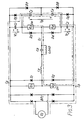
- FIG. 7 shows two discharge lamps F 1 and F 2 , which form the load, arranged in series with one another and with a primary winding T P of a transformer T (an electromagnetic coupling device).
- a capacitor C R is in parallel with the lamps and T P .
- the inductor L R is the lamp choke.
- the lamps are connected across the supply via a pair of alternatively operative switching means, as described earlier.
- a capacitive network is connected across the output of the supply, the capacitive network providing a specific capacitive circuit across one switching element of each switching means.
- the network incorporates a secondary winding T S of T 1 .
- capacitors C 2 , C 4 and C 6 operate in conjunction with switching element Q 4 and capacitors C 1 , C 3 and C5 operate in association with switching element Q 3 .
- T S is common to the specific capacitive circuits and the diodes D 1 , D 2 , D3 and D 4 bridge the respective switching elements as shown.
- Currents I B and I D therefore maintain the charge across the smoothing capacitors C 3 and C 4 throughout the supply cycles and substantially prevent current spikes being drawn from the A.C. supply.
- the current I D is proportional to the load current, so that if the current drawn by the load is reduced, the charge t Q buffer capacitors C 3 and C 4 is also reduced.
- the load comprises discharge lamps
- the energy transferred to C 3 and C 4 is reduced by the same proportion, thus preventing the over-generation of energy in C 3 and C 4 .
- I E and I A or I B Current (I E and I A or I B ) is always being drawn from the supply and the resultant supply current waveform has low harmonic distortion and a high power factor. It will be appreciated that I E is phase shifted from I A and I B . This results from the lamp current lagging the resonant current. The current drawn from the supply is therefore substantially continuous and the radio frequency interference generated is low.
- the buffer capacitance provided by capacitors C 3 and C 4 could be achieved by one large capacitor across Q 3 and Q 4 which would enable smaller capacitors to be used on the basis of capacitors C 3 and C 4 .
Applications Claiming Priority (2)
| Application Number | Priority Date | Filing Date | Title |
|---|---|---|---|
| NZ21228785 | 1985-06-04 | ||
| NZ212287 | 1985-06-04 |
Publications (3)
| Publication Number | Publication Date |
|---|---|
| EP0205287A2 true EP0205287A2 (de) | 1986-12-17 |
| EP0205287A3 EP0205287A3 (en) | 1987-10-21 |
| EP0205287B1 EP0205287B1 (de) | 1989-12-06 |
Family
ID=19921229
Family Applications (1)
| Application Number | Title | Priority Date | Filing Date |
|---|---|---|---|
| EP86304117A Expired EP0205287B1 (de) | 1985-06-04 | 1986-05-30 | Verbessertes Schaltnetzteil |
Country Status (5)
| Country | Link |
|---|---|
| US (1) | US4763239A (de) |
| EP (1) | EP0205287B1 (de) |
| AU (1) | AU579475B2 (de) |
| DE (1) | DE3667367D1 (de) |
| ZA (1) | ZA864120B (de) |
Cited By (10)
| Publication number | Priority date | Publication date | Assignee | Title |
|---|---|---|---|---|
| EP0307065A2 (de) * | 1987-09-09 | 1989-03-15 | Plaser Light Corp. | Steuereinrichtung für Entladungslampe |
| EP0352703A1 (de) * | 1988-07-27 | 1990-01-31 | Siemens Aktiengesellschaft | Elektronisches Vorschaltgerät |
| EP0392770A2 (de) * | 1989-04-14 | 1990-10-17 | TLG plc | Vorschaltschaltungen für Entladungslampen |
| EP0395159A1 (de) * | 1989-04-28 | 1990-10-31 | Koninklijke Philips Electronics N.V. | Wechselrichter zum Speisen zweier Gas und / oder Dampfentladungslampen |
| EP0395776A1 (de) * | 1989-05-02 | 1990-11-07 | Siemens Aktiengesellschaft | Elektronisches Vorschaltgerät |
| US5068573A (en) * | 1990-09-20 | 1991-11-26 | North American Philips Corporation | Power supply with energy storage for improved voltage regulation |
| WO1992004808A1 (en) * | 1990-08-31 | 1992-03-19 | Siew Ean Wong | Improvements in electronic ballasts |
| GB2261779A (en) * | 1991-11-20 | 1993-05-26 | Tokyo Electric Co Ltd | AC-DC-AC converter, particularly for fluorescent lamps |
| US5426344A (en) * | 1990-08-31 | 1995-06-20 | Ultralite International Pty Limited | Electronic ballasts |
| AU671545B2 (en) * | 1990-08-31 | 1996-08-29 | Ultralite International Pty. Limited | Improvements in electronic ballasts |
Families Citing this family (32)
| Publication number | Priority date | Publication date | Assignee | Title |
|---|---|---|---|---|
| US5111380A (en) * | 1986-10-10 | 1992-05-05 | Nilssen Ole K | Controlled series-resonance-loaded inverter |
| US4983887A (en) * | 1986-10-10 | 1991-01-08 | Nilssen Ole K | Controlled series-resonance-loaded ballast |
| US4887007A (en) * | 1987-02-18 | 1989-12-12 | U.S. Philips Corporation | DC-AC converter for supplying a gas and/or vapour discharge lamp |
| FR2613554B1 (fr) * | 1987-03-30 | 1993-05-07 | Telemecanique Electrique | Convertisseur a modulation de largeur d'impulsions |
| US4952849A (en) * | 1988-07-15 | 1990-08-28 | North American Philips Corporation | Fluorescent lamp controllers |
| US5187414A (en) * | 1988-07-15 | 1993-02-16 | North American Philips Corporation | Fluorescent lamp controllers |
| JP2585739B2 (ja) * | 1988-08-12 | 1997-02-26 | 株式会社日立製作所 | 電力変換装置 |
| DE69033820T2 (de) * | 1989-05-17 | 2002-04-11 | Koninkl Philips Electronics Nv | Schaltanordnung |
| US5402052A (en) * | 1989-05-25 | 1995-03-28 | International Business Machines Corporation | Inductive current switching system with resonance |
| AU651368B2 (en) * | 1990-08-31 | 1994-07-21 | Ultralite International Pty. Limited | Improvements in electronic ballasts |
| FI87412C (fi) * | 1991-02-25 | 1992-12-28 | Kemppi Oy | Svetsningsinverter och foerfarande foer styrning av svetsningsinverter |
| US5138233A (en) * | 1991-03-07 | 1992-08-11 | Motorola, Inc. | Driver circuit for a plurality of gas discharge lamps |
| US6121733A (en) * | 1991-06-10 | 2000-09-19 | Nilssen; Ole K. | Controlled inverter-type fluorescent lamp ballast |
| KR940009513B1 (ko) * | 1992-04-22 | 1994-10-14 | 고선웅 | 자동 점멸 형광등 점등회로 |
| US5652479A (en) * | 1995-01-25 | 1997-07-29 | Micro Linear Corporation | Lamp out detection for miniature cold cathode fluorescent lamp system |
| US5754012A (en) * | 1995-01-25 | 1998-05-19 | Micro Linear Corporation | Primary side lamp current sensing for minature cold cathode fluorescent lamp system |
| US5844378A (en) * | 1995-01-25 | 1998-12-01 | Micro Linear Corp | High side driver technique for miniature cold cathode fluorescent lamp system |
| US5818669A (en) * | 1996-07-30 | 1998-10-06 | Micro Linear Corporation | Zener diode power dissipation limiting circuit |
| US5965989A (en) * | 1996-07-30 | 1999-10-12 | Micro Linear Corporation | Transformer primary side lamp current sense circuit |
| US5825223A (en) * | 1996-07-30 | 1998-10-20 | Micro Linear Corporation | Technique for controlling the slope of a periodic waveform |
| US5896015A (en) * | 1996-07-30 | 1999-04-20 | Micro Linear Corporation | Method and circuit for forming pulses centered about zero crossings of a sinusoid |
| US5859519A (en) * | 1997-05-29 | 1999-01-12 | General Electric Company | Single phase motor drive |
| US6232727B1 (en) * | 1998-10-07 | 2001-05-15 | Micro Linear Corporation | Controlling gas discharge lamp intensity with power regulation and end of life protection |
| US6344980B1 (en) | 1999-01-14 | 2002-02-05 | Fairchild Semiconductor Corporation | Universal pulse width modulating power converter |
| US6259615B1 (en) * | 1999-07-22 | 2001-07-10 | O2 Micro International Limited | High-efficiency adaptive DC/AC converter |
| US6501234B2 (en) | 2001-01-09 | 2002-12-31 | 02 Micro International Limited | Sequential burst mode activation circuit |
| US6869157B2 (en) * | 2001-03-26 | 2005-03-22 | Canon Kabushiki Kaisha | Method of driving and controlling ink jet print head, ink jet print head, and ink jet printer |
| US20060152955A1 (en) * | 2002-08-19 | 2006-07-13 | Ryuichi Shimada | Pulse power supply for regenerating magnetic energy |
| US7057611B2 (en) * | 2003-03-25 | 2006-06-06 | 02Micro International Limited | Integrated power supply for an LCD panel |
| US6936975B2 (en) * | 2003-04-15 | 2005-08-30 | 02Micro International Limited | Power supply for an LCD panel |
| US6897698B1 (en) | 2003-05-30 | 2005-05-24 | O2Micro International Limited | Phase shifting and PWM driving circuits and methods |
| US8188682B2 (en) * | 2006-07-07 | 2012-05-29 | Maxim Integrated Products, Inc. | High current fast rise and fall time LED driver |
Citations (2)
| Publication number | Priority date | Publication date | Assignee | Title |
|---|---|---|---|---|
| US4346332A (en) * | 1980-08-14 | 1982-08-24 | General Electric Company | Frequency shift inverter for variable power control |
| GB2147159A (en) * | 1983-09-19 | 1985-05-01 | Minitronics Pty Ltd | Power converter |
Family Cites Families (8)
| Publication number | Priority date | Publication date | Assignee | Title |
|---|---|---|---|---|
| US4251752A (en) * | 1979-05-07 | 1981-02-17 | Synergetics, Inc. | Solid state electronic ballast system for fluorescent lamps |
| US4370600A (en) * | 1980-11-26 | 1983-01-25 | Honeywell Inc. | Two-wire electronic dimming ballast for fluorescent lamps |
| US4392087A (en) * | 1980-11-26 | 1983-07-05 | Honeywell, Inc. | Two-wire electronic dimming ballast for gaseous discharge lamps |
| EP0059053A3 (de) * | 1981-02-21 | 1983-05-18 | THORN EMI plc | Getakteter Schaltnetzteil |
| DE3266600D1 (en) * | 1981-02-21 | 1985-11-07 | Emi Plc Thorn | Lamp driver circuits |
| GB2115627B (en) * | 1982-02-20 | 1986-04-30 | Transtar Limited | Power supplies |
| US4511823A (en) * | 1982-06-01 | 1985-04-16 | Eaton William L | Reduction of harmonics in gas discharge lamp ballasts |
| US4639849A (en) * | 1985-05-08 | 1987-01-27 | International Exide Electronics/Corporation | Snubber circuit for H.F. bridge converter |
-
1986
- 1986-05-30 DE DE8686304117T patent/DE3667367D1/de not_active Expired - Lifetime
- 1986-05-30 EP EP86304117A patent/EP0205287B1/de not_active Expired
- 1986-06-03 US US06/870,185 patent/US4763239A/en not_active Expired - Fee Related
- 1986-06-03 AU AU58294/86A patent/AU579475B2/en not_active Ceased
- 1986-06-03 ZA ZA864120A patent/ZA864120B/xx unknown
Patent Citations (2)
| Publication number | Priority date | Publication date | Assignee | Title |
|---|---|---|---|---|
| US4346332A (en) * | 1980-08-14 | 1982-08-24 | General Electric Company | Frequency shift inverter for variable power control |
| GB2147159A (en) * | 1983-09-19 | 1985-05-01 | Minitronics Pty Ltd | Power converter |
Cited By (16)
| Publication number | Priority date | Publication date | Assignee | Title |
|---|---|---|---|---|
| EP0307065A3 (de) * | 1987-09-09 | 1989-08-30 | Plaser Light Corp. | Steuereinrichtung für Entladungslampe |
| EP0307065A2 (de) * | 1987-09-09 | 1989-03-15 | Plaser Light Corp. | Steuereinrichtung für Entladungslampe |
| EP0352703A1 (de) * | 1988-07-27 | 1990-01-31 | Siemens Aktiengesellschaft | Elektronisches Vorschaltgerät |
| EP0392770A3 (de) * | 1989-04-14 | 1992-02-12 | TLG plc | Vorschaltschaltungen für Entladungslampen |
| EP0392770A2 (de) * | 1989-04-14 | 1990-10-17 | TLG plc | Vorschaltschaltungen für Entladungslampen |
| EP0395159A1 (de) * | 1989-04-28 | 1990-10-31 | Koninklijke Philips Electronics N.V. | Wechselrichter zum Speisen zweier Gas und / oder Dampfentladungslampen |
| EP0395776A1 (de) * | 1989-05-02 | 1990-11-07 | Siemens Aktiengesellschaft | Elektronisches Vorschaltgerät |
| WO1992004808A1 (en) * | 1990-08-31 | 1992-03-19 | Siew Ean Wong | Improvements in electronic ballasts |
| GB2256099A (en) * | 1990-08-31 | 1992-11-25 | Siew Ean Wong | Improvements in electronic ballasts |
| GB2256099B (en) * | 1990-08-31 | 1994-10-19 | Siew Ean Wong | Improvements in electronic ballasts |
| US5426344A (en) * | 1990-08-31 | 1995-06-20 | Ultralite International Pty Limited | Electronic ballasts |
| AU671545B2 (en) * | 1990-08-31 | 1996-08-29 | Ultralite International Pty. Limited | Improvements in electronic ballasts |
| US5068573A (en) * | 1990-09-20 | 1991-11-26 | North American Philips Corporation | Power supply with energy storage for improved voltage regulation |
| GB2261779A (en) * | 1991-11-20 | 1993-05-26 | Tokyo Electric Co Ltd | AC-DC-AC converter, particularly for fluorescent lamps |
| US5331534A (en) * | 1991-11-20 | 1994-07-19 | Tokyo Electric Co., Ltd. | Power supply apparatus |
| GB2261779B (en) * | 1991-11-20 | 1996-03-13 | Tokyo Electric Co Ltd | Power supply apparatus |
Also Published As
| Publication number | Publication date |
|---|---|
| AU5829486A (en) | 1986-12-11 |
| ZA864120B (en) | 1987-06-24 |
| AU579475B2 (en) | 1988-11-24 |
| US4763239A (en) | 1988-08-09 |
| DE3667367D1 (de) | 1990-01-11 |
| EP0205287A3 (en) | 1987-10-21 |
| EP0205287B1 (de) | 1989-12-06 |
Similar Documents
| Publication | Publication Date | Title |
|---|---|---|
| US4763239A (en) | Switched mode power supplies | |
| US7554271B2 (en) | Single stage PFC and power converter circuit | |
| JP2559033Y2 (ja) | ガス放電ランプ用安定器 | |
| CA2314782C (en) | Multi-mode power converters incorporating balancer circuits and methods of operation thereof | |
| EP0597426A2 (de) | AC-DC Schaltung | |
| CA2058207C (en) | Inverter with shared chopper function for high input power factor with restrained higher harmonies | |
| WO1995010930A1 (en) | Integrated electronic energy converter | |
| US5789871A (en) | Series-capacitor electronic ballast | |
| JP2001513253A (ja) | 並列貯蔵直列駆動電子安定器 | |
| EP0740493B1 (de) | Betriebsgerät für Entladungslampen | |
| US5502635A (en) | Parallel resonant integrated inverter ballast for gas discharge lamps | |
| EP0602908A1 (de) | Schaltungsanordnung mit hohem Leistungsfaktor zum Betreiben einer Last | |
| US5117157A (en) | Ballast circuits for discharge lamps | |
| US4722040A (en) | Self-resonant inverter circuit | |
| JP2001211658A (ja) | 相補形スイッチを有するハロゲン電力変換器 | |
| JPH08126322A (ja) | 直流電源装置 | |
| JPS61240597A (ja) | 交流‐直流変換回路 | |
| JP3539464B2 (ja) | 電源装置および放電灯点灯装置 | |
| JP2906056B2 (ja) | 放電灯点灯回路 | |
| JP2802529B2 (ja) | 放電灯点灯装置 | |
| JPH04133297A (ja) | 電源装置 | |
| JP3261706B2 (ja) | インバータ装置 | |
| JP3134958B2 (ja) | 電源装置、放電灯点灯装置および照明装置 | |
| JP2617478B2 (ja) | 放電灯点灯装置 | |
| JPH08186982A (ja) | 直流電源装置 |
Legal Events
| Date | Code | Title | Description |
|---|---|---|---|
| PUAI | Public reference made under article 153(3) epc to a published international application that has entered the european phase |
Free format text: ORIGINAL CODE: 0009012 |
|
| AK | Designated contracting states |
Kind code of ref document: A2 Designated state(s): DE FR GB IT NL |
|
| PUAL | Search report despatched |
Free format text: ORIGINAL CODE: 0009013 |
|
| AK | Designated contracting states |
Kind code of ref document: A3 Designated state(s): DE FR GB IT NL |
|
| 17P | Request for examination filed |
Effective date: 19880324 |
|
| 17Q | First examination report despatched |
Effective date: 19880802 |
|
| GRAA | (expected) grant |
Free format text: ORIGINAL CODE: 0009210 |
|
| AK | Designated contracting states |
Kind code of ref document: B1 Designated state(s): DE FR GB IT NL |
|
| REF | Corresponds to: |
Ref document number: 3667367 Country of ref document: DE Date of ref document: 19900111 |
|
| ET | Fr: translation filed | ||
| ITF | It: translation for a ep patent filed |
Owner name: FUMERO BREVETTI S.N.C. |
|
| PLBE | No opposition filed within time limit |
Free format text: ORIGINAL CODE: 0009261 |
|
| STAA | Information on the status of an ep patent application or granted ep patent |
Free format text: STATUS: NO OPPOSITION FILED WITHIN TIME LIMIT |
|
| 26N | No opposition filed | ||
| ITTA | It: last paid annual fee | ||
| PGFP | Annual fee paid to national office [announced via postgrant information from national office to epo] |
Ref country code: GB Payment date: 19920526 Year of fee payment: 7 |
|
| PGFP | Annual fee paid to national office [announced via postgrant information from national office to epo] |
Ref country code: FR Payment date: 19920529 Year of fee payment: 7 |
|
| PGFP | Annual fee paid to national office [announced via postgrant information from national office to epo] |
Ref country code: NL Payment date: 19920531 Year of fee payment: 7 |
|
| PGFP | Annual fee paid to national office [announced via postgrant information from national office to epo] |
Ref country code: DE Payment date: 19920728 Year of fee payment: 7 |
|
| PG25 | Lapsed in a contracting state [announced via postgrant information from national office to epo] |
Ref country code: GB Effective date: 19930530 |
|
| PG25 | Lapsed in a contracting state [announced via postgrant information from national office to epo] |
Ref country code: NL Effective date: 19931201 |
|
| NLV4 | Nl: lapsed or anulled due to non-payment of the annual fee | ||
| GBPC | Gb: european patent ceased through non-payment of renewal fee |
Effective date: 19930530 |
|
| PG25 | Lapsed in a contracting state [announced via postgrant information from national office to epo] |
Ref country code: FR Effective date: 19940131 |
|
| PG25 | Lapsed in a contracting state [announced via postgrant information from national office to epo] |
Ref country code: DE Effective date: 19940201 |
|
| REG | Reference to a national code |
Ref country code: FR Ref legal event code: ST |
|
| PG25 | Lapsed in a contracting state [announced via postgrant information from national office to epo] |
Ref country code: IT Free format text: LAPSE BECAUSE OF NON-PAYMENT OF DUE FEES Effective date: 20050530 |