EP0204662B2 - Regelbare Unterstützung für Rauchabsaugvorrichtungen - Google Patents
Regelbare Unterstützung für Rauchabsaugvorrichtungen Download PDFInfo
- Publication number
- EP0204662B2 EP0204662B2 EP86830027A EP86830027A EP0204662B2 EP 0204662 B2 EP0204662 B2 EP 0204662B2 EP 86830027 A EP86830027 A EP 86830027A EP 86830027 A EP86830027 A EP 86830027A EP 0204662 B2 EP0204662 B2 EP 0204662B2
- Authority
- EP
- European Patent Office
- Prior art keywords
- rigid
- suction
- parallelogram
- hood
- fume
- Prior art date
- Legal status (The legal status is an assumption and is not a legal conclusion. Google has not performed a legal analysis and makes no representation as to the accuracy of the status listed.)
- Expired - Lifetime
Links
Images


Classifications
-
- F—MECHANICAL ENGINEERING; LIGHTING; HEATING; WEAPONS; BLASTING
- F16—ENGINEERING ELEMENTS AND UNITS; GENERAL MEASURES FOR PRODUCING AND MAINTAINING EFFECTIVE FUNCTIONING OF MACHINES OR INSTALLATIONS; THERMAL INSULATION IN GENERAL
- F16L—PIPES; JOINTS OR FITTINGS FOR PIPES; SUPPORTS FOR PIPES, CABLES OR PROTECTIVE TUBING; MEANS FOR THERMAL INSULATION IN GENERAL
- F16L27/00—Adjustable joints, Joints allowing movement
- F16L27/08—Adjustable joints, Joints allowing movement allowing adjustment or movement only about the axis of one pipe
- F16L27/0861—Arrangements of joints with one another and with pipes or hoses
-
- B—PERFORMING OPERATIONS; TRANSPORTING
- B08—CLEANING
- B08B—CLEANING IN GENERAL; PREVENTION OF FOULING IN GENERAL
- B08B15/00—Preventing escape of dirt or fumes from the area where they are produced; Collecting or removing dirt or fumes from that area
- B08B15/002—Preventing escape of dirt or fumes from the area where they are produced; Collecting or removing dirt or fumes from that area using a central suction system, e.g. for collecting exhaust gases in workshops
-
- F—MECHANICAL ENGINEERING; LIGHTING; HEATING; WEAPONS; BLASTING
- F16—ENGINEERING ELEMENTS AND UNITS; GENERAL MEASURES FOR PRODUCING AND MAINTAINING EFFECTIVE FUNCTIONING OF MACHINES OR INSTALLATIONS; THERMAL INSULATION IN GENERAL
- F16L—PIPES; JOINTS OR FITTINGS FOR PIPES; SUPPORTS FOR PIPES, CABLES OR PROTECTIVE TUBING; MEANS FOR THERMAL INSULATION IN GENERAL
- F16L27/00—Adjustable joints, Joints allowing movement
- F16L27/08—Adjustable joints, Joints allowing movement allowing adjustment or movement only about the axis of one pipe
- F16L27/0849—Adjustable joints, Joints allowing movement allowing adjustment or movement only about the axis of one pipe the fluid being turned through an angle when passing from one joint element to another
- F16L27/0857—Adjustable joints, Joints allowing movement allowing adjustment or movement only about the axis of one pipe the fluid being turned through an angle when passing from one joint element to another with hinge and bellows sealing
Definitions
- the present invention relates to an adjustable support for a smoke- or fume-exhauster and the like. More particularly, this invention relates to a support of said type having structural and functional properties such as to assure a very high flexibility of employment. Moreover, the support according to the present invention, in addition to be made of a modular structure, gives the possibility of keeping the orientation of the suction hood in the desired position, even in the case of moving the suction arm and shifting the same in any direction and through any angle.
- Smoke- or fume-exhausters and the like are increasingly employed at the present time in the industrial field.
- the device disclosed in the Italian patent 967309 provides a supporting structure inside the flexible suction tube, said structure being centrally articulated, as well as articulated at the connection point with the suction box. It is well evident that a structure provided inside the suction tube gives rise to a number of problems and drawbacks because of the fact that the material so sucked comes in contact with the supporting structure and deposits on the same, so as to compromise possibly the good performance of the device, and in addition because of load losses which occur, so that it is necessary to oversize the suction system.
- the device that is the object of the Italian patent No. 1058789 in the name of CORAL S.a.s., provides a structure made up of two (or more) rigid tube members which are articulated at theircon- nections and whose actions counteracting the friction forces at the connection points are obtained, for the first arm, through a large spring fastened to the connection end of the exhauster and to the articulation point, whereas no such action is provided for the next arms, so that the structure is quite heavy and hard to move. Said device does not allow to keep the orientation of the suction hood unaltered when the position of the arm is changed.
- the eldest solution (1.033.016) comprised a structure having a tubular conduct connecting the solution inlet to the suction fan made up of two or more rigid suction tubes connected by sections flexible hose and reciprocally articulated by collars realizing articulated elbows.
- the adjustable support according to the present invention aims at obviating these and other drawbacks by providing a device which consists of a modular structure comprising two or more articulated parallelograms, whose lower arm is the same suction tube, said parallelograms being articulated centrally by means of a four points transmission plate which allows said parallelogram to close completely so that the articulating capacity of the support is increased.
- the supporting action is obtained in the support according to the present invention through springs, the frictions provided at the various hinge points having the function of compensating the spring actions.
- the support according to the present invention allows the orientation of the suction hood to be kept unaltered also when the arm is moved.
- Afurther object of the present invention is that of supplying a double-friction articulation system of the suction hood, so that the orientation of such system keeps unaltered unless said hood is directly acted upon.
- an adjustable support for smoke- or fume-exhausters and the like comprising rigid suction tubes and flexible conduit sections extending between said exhauster and the discharge end of the first rigid suction tube, between the intake end of said first rigid suction tube and the discharge end of said second suction tube, and between the intake end of said second suction tube and an intake hood, so that a continuous exhaust passage between said intake hood and said exhauster is realized, and parallelogram means consisting of rod means and of a rigid suction tube, each one associated to a pair of compensating springs and a couple of four point transmission plates, provided between each couple of adjacent parallelograms, characterized in that said four transmission plates are trapezium shaped and have inferior sides closest to the inner side of the flexible section longer than the diameter of said suction tubes, and in that said compensating springs associated to each of said parallelograms are fastened with their upper part to the upper side of the plates at a point lying on the line vertical to the inferiorside of the plate and passing through the inferior hinge point
- the compensating springs associated to each of said parallelograms are fastened at the upper part to a point on the vertical line of the lower hinge point of the parallelogram so as to avoid the presence of a residual angle which, in the position of maximum extension of the spring, would alter the equilibrium state of the whole system.
- two inverted U-shaped sections or inverted “channels” can be provided which are laterally fastened to said rigid tube through bolts, which give a higher stiffness to the structure so consisting of the same together with said rigid tube one end of said compensating spring pairs being centrally coupled to said U-shaped sections, and the respective articulation points being hinged at the two end.
- a doube-friction system is provided at the end of the parallelogram where the suction hood is coupled at the articulation point of said upper rods, of said rigid tube as well as of said suction hood, said friction system experiencing between the upper rod and the rigid pipe a friction lower than the friction occurring between the rigid pipe and the articulation point of said hood, so that motions given to the two parallelograms as a whole do not give rise to motions of said hood.
- an angle section or L-shaped rod can be provided which is hinged at the upper part with an upper rod of said parallelogram, at the center position, on the connection system between the rigid pipe, the length of the flexible hose between the rigid tube and the hood, and, at the lower part, on an articulation plate of the hood itself, the friction system of lower friction action being provided at said central hinge, the friction system of higher friction action being provided at said lower hinge, and a similar system being provided between the other upper rod of the parallelogram and the articulation point of said hood.
- the suction arm can be acted upon as desired without changing the angular orientation of the hood.
- a rod is provided between said four point transmission plates, which rod is transversal and fastened at the connection point of said compensating springs associated to the parallelogram, such rod transmitting in that way a fraction of the present stress.
- two such parallelograms are provided, in series.
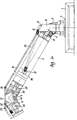
- an exhauster 1 of the known type bears at the upper part a revolving or rotating connection member 2 to which the suction tube is attached through a length of a flexible hose 3 ending with a bush 4.
- the suction tube in addition is made up of a first rigid tube 5, a second length of a flexible hose 6, a second rigid tube 7 and a third length of a flexible hose 8.
- the small suction hood 9 is provided at the end of the hose 8 .
- Such fastening is of a direct type at the point 12 and 12' as regards the upper rods 10 and 10', whereas the fastening action occurs through the interposition of a plate 13 as regards the tube 5.
- Friction members are provided at points 12, 12' and 14, 14' where hinges are placed, said friction members being interposed between the single members hinged at said points and movable with respect to each other.
- the second parallelogram similarly to the first one, is made up of the rigid tube 7 and of two upper rods 15 and 15'. Said rods 15,15'are hinged at 16 and 16', two plates 17 and 17', hinged at 18, 18', beginning at said points 16, 16'. Moreover, two plates 10 and 19' rigidly connected to the rigid tube 7 at points indicated with references 20 and 21 are hinged at the points 18, 18'.
- Ashaped plate 22 is also hinged at the points 18, 18', which plate is connected to the small suction hood 9 through the rod 23 which is articulated at point 24, the articulated joint 25 and the L-shaped rod 26, so as to control the motions of said hood.
- a double friction system is provided at the articulation joint 18,18' so as to cause the motions of the articulated parallelograms assembly to be independent of the motions of the small suction hoods.
- friction systems will be provided between the plates 17,19 and 17', 19', which systems exert a friction force lower than those provided between the plates 17,17'and 22.
- the orientation of the small hood 9 will be fixed manually and independently of the motions of the suction tube, that is, independently of the rotation about points indicated with reference 18, 18' as regards the vertical motions, about point 24 as regards the horizontal motions, and about point 25 as regards rotatory motions.
- the friction system with higher friction force will be arranged at the lower hinge point, whereas the system with lower friction value will be arranged at the central hinge point.
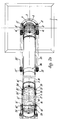
- Two transmission plates 27, 27' with four points are provided at the point of the central articulation joint between the two parallelogram systems. Said four points transmission plates 27, 27' allow the parallelogram assembly to close completely.
- the rods 10, 10' are hinged at points indicated with references 28, 28', whereas the rods 15, 15' are hinged at points 29, 29'.
- the two rigid pipes 5 and 7 are hinged in their turn at the points 30, 30' and 31, 31' through two pairs of plates 32, 32' and 33, 33' which are rigidly connected to the same.
- a first pair of compensating springs 35, 35' is provided between the plates 11, 11' and a central collar 36 on the tube 5, on which said springs are fastened at the points 37 and 37'.
- a second pair of springs 38, 38' is provided between the central collar 39 on the pipe 7, on which the transmission plates 27, 27' are fastened at the points 40, 40'.
- a structure of the kind disclosed above, in which the parallelogram properties are exploited, also allows to obtain a constant deflection of the spring because a progressive compensation caused by the reduction of the angular displacement corresponds to an increased extension of the springs.
- a rod 43 is provided between the two transmission plates 27 and 27', more exactly between the two coupling points 42 and 42' of the springs 38, 38', which rod, by acting as a strut, transmits a fraction of the stress.
Landscapes
- Engineering & Computer Science (AREA)
- General Engineering & Computer Science (AREA)
- Mechanical Engineering (AREA)
- Ventilation (AREA)
- Exhaust Silencers (AREA)
- Respiratory Apparatuses And Protective Means (AREA)
- Prevention Of Fouling (AREA)
- Compounds Of Unknown Constitution (AREA)
- Organic Low-Molecular-Weight Compounds And Preparation Thereof (AREA)
- Exhaust Gas After Treatment (AREA)
- Incineration Of Waste (AREA)
- Supports For Pipes And Cables (AREA)
Claims (5)
Priority Applications (1)
| Application Number | Priority Date | Filing Date | Title |
|---|---|---|---|
| AT86830027T ATE42915T1 (de) | 1985-02-06 | 1986-02-03 | Regelbare unterstuetzung fuer rauchabsaugvorrichtungen. |
Applications Claiming Priority (2)
| Application Number | Priority Date | Filing Date | Title |
|---|---|---|---|
| IT47643/85A IT1182179B (it) | 1985-02-06 | 1985-02-06 | Supporto regolabile per apparecchi aspiratori di fumi esalazioni e simili |
| IT4764385 | 1985-02-06 |
Publications (3)
| Publication Number | Publication Date |
|---|---|
| EP0204662A1 EP0204662A1 (de) | 1986-12-10 |
| EP0204662B1 EP0204662B1 (de) | 1989-05-10 |
| EP0204662B2 true EP0204662B2 (de) | 1993-03-31 |
Family
ID=11261628
Family Applications (1)
| Application Number | Title | Priority Date | Filing Date |
|---|---|---|---|
| EP86830027A Expired - Lifetime EP0204662B2 (de) | 1985-02-06 | 1986-02-03 | Regelbare Unterstützung für Rauchabsaugvorrichtungen |
Country Status (7)
| Country | Link |
|---|---|
| US (1) | US4699046A (de) |
| EP (1) | EP0204662B2 (de) |
| AT (1) | ATE42915T1 (de) |
| CA (1) | CA1268074A (de) |
| DE (1) | DE3663228D1 (de) |
| ES (1) | ES8701355A1 (de) |
| IT (1) | IT1182179B (de) |
Families Citing this family (27)
| Publication number | Priority date | Publication date | Assignee | Title |
|---|---|---|---|---|
| SE8702139L (sv) * | 1987-05-22 | 1988-11-23 | Stefan J Moszkowski | Sugkaapa foer anslutning till ett punktsugsystem |
| DE3805425C1 (de) * | 1988-02-22 | 1989-02-02 | Rittal-Werk Rudolf Loh Gmbh & Co Kg, 6348 Herborn, De | |
| JPH0253187U (de) * | 1988-10-05 | 1990-04-17 | ||
| DE4116464A1 (de) * | 1991-05-21 | 1992-11-26 | Loh Kg Rittal Werk | Tragarm fuer eine aufhaengevorrichtung von steuergeraeten, steuertafeln und dgl. |
| SE469622B (sv) * | 1991-08-26 | 1993-08-09 | Nederman Philip & Co Ab | Staellbar anordning foer utsugning och/eller tillfoersel av gas |
| SE506161C2 (sv) * | 1991-12-13 | 1997-11-17 | Plymovent Ab | Punktutsug |
| SE506838C2 (sv) * | 1992-04-21 | 1998-02-16 | Plymex Fabriksfoersaeljning Ab | Inställbar punktutsugningsanordning med filter |
| SE507903C2 (sv) * | 1993-07-12 | 1998-07-27 | Nederman Philip & Co Ab | Anordning för utsugning av hälsofarliga gaser från arbetsplatser |
| NL9301563A (nl) * | 1993-09-09 | 1995-04-03 | Euromate Ind Air Cleaning Syst | Inrichting voor het afzuigen van gas of dergelijke. |
| US5362273A (en) * | 1994-01-19 | 1994-11-08 | Exhaust Track, Inc. | Vehicle exhaust distribution system for buildings |
| US5536206A (en) * | 1995-02-10 | 1996-07-16 | Airflow Systems, Inc. | Articulated duct fume collection and exhaust apparatus |
| US5609298A (en) * | 1995-11-03 | 1997-03-11 | Hyslop; William J. | Exhaust nozzle assembly for an exhaust extraction system |
| US5655962A (en) * | 1996-01-22 | 1997-08-12 | Exhaust Track, Inc. | Continuous seal vehicular exhaust distribution system for building |
| IT1291164B1 (it) | 1997-03-04 | 1998-12-29 | Coral Spa | Condotto universale di convogliamento di fumi o gas nocivi da un posto di lavorazione. |
| US5927759A (en) * | 1998-06-30 | 1999-07-27 | Hyslop; William J. | Connection assembly for an exhaust extraction system |
| US6308707B1 (en) * | 1999-02-10 | 2001-10-30 | Li-Chow Lu | Vacuum equipment for medical tables |
| JP3700824B2 (ja) | 1999-07-26 | 2005-09-28 | トヨタ自動車株式会社 | 回転速度検出装置 |
| US6354937B1 (en) | 2000-02-05 | 2002-03-12 | Dale J. Crook | Flexible duct sleeve |
| US20050161945A1 (en) * | 2004-01-23 | 2005-07-28 | San Ford Machinery Co., Ltd. | Cantilever wind-exhausting pipe |
| ITMI20040380A1 (it) * | 2004-03-02 | 2004-06-02 | Airbox Srl | Braccio aspirante a pantografo con ancoraggio variabile delle molle di bilanciamento |
| DE102004032636A1 (de) * | 2004-07-06 | 2006-02-16 | Max Homeier | Vorrichtung zum Absaugen von Küchendunst |
| CN101678408B (zh) * | 2007-05-11 | 2012-09-26 | 福迈克斯股份公司 | 安装装置、接头结构、通风臂以及通风系统 |
| US7527305B2 (en) * | 2007-05-31 | 2009-05-05 | Hyslop William J | Hose connector with adjustable ambient air inlets |
| US8038175B2 (en) * | 2007-09-20 | 2011-10-18 | Crook Dale J | HVAC duct assembly and support |
| US7914047B2 (en) * | 2007-09-20 | 2011-03-29 | Crook Dale J | Support for flexible duct bend |
| US20130052928A1 (en) * | 2011-08-24 | 2013-02-28 | Björn L. WOLFHAGEN | Exhaust extraction system |
| SE542019C2 (en) * | 2018-06-08 | 2020-02-11 | Fumex Ab | Support arm arrangement for a local gas extractor, and a local gas extractor with such a support arm arrangement |
Family Cites Families (8)
| Publication number | Priority date | Publication date | Assignee | Title |
|---|---|---|---|---|
| US1075541A (en) * | 1911-10-02 | 1913-10-14 | White S Dental Mfg Co | Bracket. |
| SE424409B (sv) * | 1975-12-04 | 1982-07-19 | Coral Sas | Anordning for lokaliserad utsugning av gaser, rokstoft och liknande |
| GB1506886A (en) * | 1976-07-26 | 1978-04-12 | Cleen Flo Ltd | Devices for exhausting fumes or dust from work stations |
| GB2002871A (en) * | 1977-06-03 | 1979-02-28 | Noble Distribution Ltd | Improvements in and relating to flexible ducting |
| FI54401C (fi) * | 1977-07-12 | 1978-11-10 | Lival Oy Ab | Ledanordning vid belysningsarmaturer saosom kontorslampor |
| FR2499395A1 (fr) * | 1981-02-10 | 1982-08-13 | Amphoux Andre | Conduit deformable tel que bras d'aspiration de fluide gazeux |
| JPS6057345B2 (ja) * | 1981-09-04 | 1985-12-14 | 義一 多田 | 歯科診療室の汚染浄化方法および汚染浄化装置 |
| DE3225953A1 (de) * | 1982-07-10 | 1984-01-12 | Schmidt, Kranz & Co GmbH Zweigniederlassung Zorge, 3421 Zorge | Absaugarm zum absaugen von rauch und gasen |
-
1985
- 1985-02-06 IT IT47643/85A patent/IT1182179B/it active
-
1986
- 1986-02-03 US US06/825,322 patent/US4699046A/en not_active Expired - Fee Related
- 1986-02-03 AT AT86830027T patent/ATE42915T1/de not_active IP Right Cessation
- 1986-02-03 DE DE8686830027T patent/DE3663228D1/de not_active Expired
- 1986-02-03 EP EP86830027A patent/EP0204662B2/de not_active Expired - Lifetime
- 1986-02-05 ES ES551661A patent/ES8701355A1/es not_active Expired
- 1986-02-06 CA CA000501255A patent/CA1268074A/en not_active Expired - Fee Related
Also Published As
| Publication number | Publication date |
|---|---|
| CA1268074A (en) | 1990-04-24 |
| ES551661A0 (es) | 1986-11-16 |
| EP0204662B1 (de) | 1989-05-10 |
| IT8547643A0 (it) | 1985-02-06 |
| US4699046A (en) | 1987-10-13 |
| ATE42915T1 (de) | 1989-05-15 |
| DE3663228D1 (en) | 1989-06-15 |
| ES8701355A1 (es) | 1986-11-16 |
| EP0204662A1 (de) | 1986-12-10 |
| IT8547643A1 (it) | 1986-08-06 |
| IT1182179B (it) | 1987-09-30 |
Similar Documents
| Publication | Publication Date | Title |
|---|---|---|
| EP0204662B2 (de) | Regelbare Unterstützung für Rauchabsaugvorrichtungen | |
| US4158462A (en) | Localized suction device with a sucking inlet head carried by a tubular duct end orientable in space | |
| US6524180B1 (en) | Adjustable duct assembly for fume and dust removal | |
| DE3261320D1 (en) | Vacuum arm in the form of a variable pipe for gaseous media | |
| CA2281558A1 (en) | All-purpose conduit for conveying harmful fumes or gases away from a work station | |
| CA2149620A1 (en) | Height adjustable conveyor system | |
| JP3606875B2 (ja) | 掻き取りにより掃除可能な手動選択連結装置 | |
| CA2036921C (en) | Temporary selective connection installation with multiple fluid inlets and outlets | |
| US4207920A (en) | Swivel assembly for interconnecting two relatively movable conduits | |
| US5024211A (en) | Heat exchange medium connector for movable solar heaters | |
| DE3868545D1 (de) | Verbindung zweier rohre einer leitung fuer heisse medien. | |
| CA2108275C (en) | Support arm | |
| GB2042466A (en) | Articulated fluid loading arm | |
| GB2289034A (en) | Loading arm | |
| KR100315541B1 (ko) | 작업장으로부터 발생되는 유해가스를 이송하기 위한 관 | |
| EP0516213B1 (de) | Ellbogengelenkverbindung mit einem einstückigen Gelenkarmpaar mit entsprechenden Spannschellen | |
| CN218031989U (zh) | 一种废气治理用废气处理输送机构 | |
| GB2084216A (en) | Power adjustable, jointed pipe sections for goaf-stowing pneumatic conveyer system | |
| JPS6245435B2 (de) | ||
| SU1305490A1 (ru) | Шарнирный компенсатор дл трубопроводов | |
| MXPA99008053A (en) | All-purpose conduit for conveying harmful fumes or gases away from a work station | |
| GB2028258A (en) | A fluid transfer system | |
| SU887872A2 (ru) | Устройство дл соединени труб посредством муфты | |
| ES289778U (es) | Dispositivo de soporte y de sujecion rigida de una tuberia. | |
| RU2275542C2 (ru) | Узел компенсации температурных удлинений трубопроводов |
Legal Events
| Date | Code | Title | Description |
|---|---|---|---|
| PUAI | Public reference made under article 153(3) epc to a published international application that has entered the european phase |
Free format text: ORIGINAL CODE: 0009012 |
|
| AK | Designated contracting states |
Kind code of ref document: A1 Designated state(s): AT BE CH DE FR GB IT LI LU NL SE |
|
| 17P | Request for examination filed |
Effective date: 19870514 |
|
| 17Q | First examination report despatched |
Effective date: 19880204 |
|
| GRAA | (expected) grant |
Free format text: ORIGINAL CODE: 0009210 |
|
| AK | Designated contracting states |
Kind code of ref document: B1 Designated state(s): AT BE CH DE FR GB IT LI LU NL SE |
|
| REF | Corresponds to: |
Ref document number: 42915 Country of ref document: AT Date of ref document: 19890515 Kind code of ref document: T |
|
| ITF | It: translation for a ep patent filed |
Owner name: BARZANO' E ZANARDO ROMA S.P.A. |
|
| REF | Corresponds to: |
Ref document number: 3663228 Country of ref document: DE Date of ref document: 19890615 |
|
| ET | Fr: translation filed | ||
| PLBI | Opposition filed |
Free format text: ORIGINAL CODE: 0009260 |
|
| 26 | Opposition filed |
Opponent name: AB PH. NEDERMAN & CO. Effective date: 19900208 |
|
| NLR1 | Nl: opposition has been filed with the epo |
Opponent name: AB PH. NEDERMAN & CO. |
|
| PGFP | Annual fee paid to national office [announced via postgrant information from national office to epo] |
Ref country code: LU Payment date: 19911218 Year of fee payment: 7 |
|
| ITTA | It: last paid annual fee | ||
| EPTA | Lu: last paid annual fee | ||
| PG25 | Lapsed in a contracting state [announced via postgrant information from national office to epo] |
Ref country code: LU Free format text: LAPSE BECAUSE OF NON-PAYMENT OF DUE FEES Effective date: 19930203 |
|
| PUAH | Patent maintained in amended form |
Free format text: ORIGINAL CODE: 0009272 |
|
| STAA | Information on the status of an ep patent application or granted ep patent |
Free format text: STATUS: PATENT MAINTAINED AS AMENDED |
|
| 27A | Patent maintained in amended form |
Effective date: 19930331 |
|
| AK | Designated contracting states |
Kind code of ref document: B2 Designated state(s): AT BE CH DE FR GB IT LI LU NL SE |
|
| REG | Reference to a national code |
Ref country code: CH Ref legal event code: AEN |
|
| ITF | It: translation for a ep patent filed |
Owner name: MARCHI & MITTLER S.R.L. |
|
| NLR2 | Nl: decision of opposition | ||
| ET3 | Fr: translation filed ** decision concerning opposition | ||
| NLR3 | Nl: receipt of modified translations in the netherlands language after an opposition procedure | ||
| EAL | Se: european patent in force in sweden |
Ref document number: 86830027.8 |
|
| PGFP | Annual fee paid to national office [announced via postgrant information from national office to epo] |
Ref country code: AT Payment date: 20010222 Year of fee payment: 16 |
|
| REG | Reference to a national code |
Ref country code: GB Ref legal event code: IF02 |
|
| PG25 | Lapsed in a contracting state [announced via postgrant information from national office to epo] |
Ref country code: AT Free format text: LAPSE BECAUSE OF NON-PAYMENT OF DUE FEES Effective date: 20020203 |
|
| PGFP | Annual fee paid to national office [announced via postgrant information from national office to epo] |
Ref country code: GB Payment date: 20020206 Year of fee payment: 17 |
|
| PGFP | Annual fee paid to national office [announced via postgrant information from national office to epo] |
Ref country code: NL Payment date: 20020228 Year of fee payment: 17 |
|
| PG25 | Lapsed in a contracting state [announced via postgrant information from national office to epo] |
Ref country code: GB Free format text: LAPSE BECAUSE OF NON-PAYMENT OF DUE FEES Effective date: 20030203 |
|
| PGFP | Annual fee paid to national office [announced via postgrant information from national office to epo] |
Ref country code: SE Payment date: 20030213 Year of fee payment: 18 |
|
| PGFP | Annual fee paid to national office [announced via postgrant information from national office to epo] |
Ref country code: DE Payment date: 20030221 Year of fee payment: 18 |
|
| PG25 | Lapsed in a contracting state [announced via postgrant information from national office to epo] |
Ref country code: NL Free format text: LAPSE BECAUSE OF NON-PAYMENT OF DUE FEES Effective date: 20030901 |
|
| GBPC | Gb: european patent ceased through non-payment of renewal fee | ||
| NLV4 | Nl: lapsed or anulled due to non-payment of the annual fee |
Effective date: 20030901 |
|
| PG25 | Lapsed in a contracting state [announced via postgrant information from national office to epo] |
Ref country code: SE Free format text: LAPSE BECAUSE OF NON-PAYMENT OF DUE FEES Effective date: 20040204 |
|
| PGFP | Annual fee paid to national office [announced via postgrant information from national office to epo] |
Ref country code: BE Payment date: 20040323 Year of fee payment: 19 |
|
| PG25 | Lapsed in a contracting state [announced via postgrant information from national office to epo] |
Ref country code: DE Free format text: LAPSE BECAUSE OF NON-PAYMENT OF DUE FEES Effective date: 20040901 |
|
| EUG | Se: european patent has lapsed | ||
| PGFP | Annual fee paid to national office [announced via postgrant information from national office to epo] |
Ref country code: FR Payment date: 20050222 Year of fee payment: 20 |
|
| PGFP | Annual fee paid to national office [announced via postgrant information from national office to epo] |
Ref country code: IT Payment date: 20050224 Year of fee payment: 20 Ref country code: CH Payment date: 20050224 Year of fee payment: 20 |
|
| PG25 | Lapsed in a contracting state [announced via postgrant information from national office to epo] |
Ref country code: BE Free format text: LAPSE BECAUSE OF NON-PAYMENT OF DUE FEES Effective date: 20050228 |
|
| BERE | Be: lapsed |
Owner name: *AIRBOX S.R.L. Effective date: 20050228 |
|
| REG | Reference to a national code |
Ref country code: CH Ref legal event code: PL |
|
| BERE | Be: lapsed |
Owner name: *AIRBOX S.R.L. Effective date: 20050228 |