EP0204635B1 - Verfahren zur Übertragung von digitaler Information in Wörterblöcken - Google Patents
Verfahren zur Übertragung von digitaler Information in Wörterblöcken Download PDFInfo
- Publication number
- EP0204635B1 EP0204635B1 EP86401185A EP86401185A EP0204635B1 EP 0204635 B1 EP0204635 B1 EP 0204635B1 EP 86401185 A EP86401185 A EP 86401185A EP 86401185 A EP86401185 A EP 86401185A EP 0204635 B1 EP0204635 B1 EP 0204635B1
- Authority
- EP
- European Patent Office
- Prior art keywords
- words
- bits
- linked
- information
- redundancy
- Prior art date
- Legal status (The legal status is an assumption and is not a legal conclusion. Google has not performed a legal analysis and makes no representation as to the accuracy of the status listed.)
- Expired - Lifetime
Links
- 238000000034 method Methods 0.000 title claims abstract description 58
- 230000005540 biological transmission Effects 0.000 claims abstract description 31
- 208000011580 syndromic disease Diseases 0.000 claims description 92
- 239000011159 matrix material Substances 0.000 claims description 54
- 239000013598 vector Substances 0.000 claims description 46
- 238000001514 detection method Methods 0.000 claims description 10
- 230000015654 memory Effects 0.000 description 19
- 238000004364 calculation method Methods 0.000 description 8
- 238000010200 validation analysis Methods 0.000 description 7
- 230000000873 masking effect Effects 0.000 description 5
- 238000009432 framing Methods 0.000 description 4
- 230000006870 function Effects 0.000 description 4
- 230000000875 corresponding effect Effects 0.000 description 2
- 230000005236 sound signal Effects 0.000 description 2
- 101100422780 Caenorhabditis elegans sur-5 gene Proteins 0.000 description 1
- 230000002159 abnormal effect Effects 0.000 description 1
- 230000002596 correlated effect Effects 0.000 description 1
- 125000004122 cyclic group Chemical group 0.000 description 1
- 230000007547 defect Effects 0.000 description 1
- 230000009977 dual effect Effects 0.000 description 1
- 239000000428 dust Substances 0.000 description 1
- 235000021183 entrée Nutrition 0.000 description 1
- 238000000605 extraction Methods 0.000 description 1
- 230000000737 periodic effect Effects 0.000 description 1
- 238000004904 shortening Methods 0.000 description 1
- 230000001360 synchronised effect Effects 0.000 description 1
- 230000003936 working memory Effects 0.000 description 1
Images


Classifications
-
- G—PHYSICS
- G11—INFORMATION STORAGE
- G11B—INFORMATION STORAGE BASED ON RELATIVE MOVEMENT BETWEEN RECORD CARRIER AND TRANSDUCER
- G11B20/00—Signal processing not specific to the method of recording or reproducing; Circuits therefor
- G11B20/10—Digital recording or reproducing
- G11B20/18—Error detection or correction; Testing, e.g. of drop-outs
- G11B20/1806—Pulse code modulation systems for audio signals
- G11B20/1809—Pulse code modulation systems for audio signals by interleaving
-
- H—ELECTRICITY
- H03—ELECTRONIC CIRCUITRY
- H03M—CODING; DECODING; CODE CONVERSION IN GENERAL
- H03M13/00—Coding, decoding or code conversion, for error detection or error correction; Coding theory basic assumptions; Coding bounds; Error probability evaluation methods; Channel models; Simulation or testing of codes
- H03M13/03—Error detection or forward error correction by redundancy in data representation, i.e. code words containing more digits than the source words
- H03M13/05—Error detection or forward error correction by redundancy in data representation, i.e. code words containing more digits than the source words using block codes, i.e. a predetermined number of check bits joined to a predetermined number of information bits
- H03M13/13—Linear codes
Definitions
- the present invention relates to a method of transmitting digital information word blocks. It relates more particularly to a coding and decoding technique in which transmission blocks are formed each composed of a series of digital information words and associated redundancy words, these redundancy words being constructed so as to detect and to correct, upon reception, packets of errors of great length, such as those encountered in digital recording on magnetic tape.
- the information to be recorded is organized in frames each comprising a synchronization word, an identification word, one or more information words and a detector code d 'fault.
- This error detecting code may not detect all errors.
- the information words are separated into a sequence of even information words and a sequence of odd information words. These sequences are coded and transmitted with a time offset.
- This technique avoids that a fault affecting the transmission channel, or the recording medium, causes an error on two consecutive information words. An incorrectly recognized information word can thus be corrected or, if correction is not possible, interpolated from the previous information word and the next information word. This interpolation obviously has a meaning only if the successive information words are correlated, which is in particular the case in digital recording of a sound signal.
- the transmission or recording format has a sliding structure, that is to say that the interlacing of the frames is such that it is impossible to define independent blocks as is the case in article cited.
- the object of the invention is in particular to remedy the drawbacks of known transmission methods and for objective a method of transmission in independent blocks, in order to be able to make mounting easily, in particular electronic mounting.
- Another object of the invention is a transmission method capable of withstanding a loss of information occurring over the entire width of a magnetic tape over a length of approximately 5 to 10 mm, in the case where the recording is carried out in parallel on several magnetic tracks, and suitable for resist the complete loss of a magnetic strip when the information is distributed for example on four magnetic tracks.
- Another object of the invention is a transmission method making it possible to correct at least three errors, that is to say a transmission method in which the probability of non-correctable error is proportional to p4, when the probability of having an error is equal to p.
- the invention finally aims to detect and correct errors not detected by the error detector codes protecting the information and redundancy words.
- the redundancy words are preferably obtained by an extended Hamming code, that is to say of the form (2 m , 2 m -m-1), where m is an integer. But it is also possible to use a normal Hamming code of the form (2 m -1, 2 m -m-1). In both cases, the code can be shortened. It is then respectively of the form (2 m -p, 2 m -m-1-p) or of the form 2 m -1-p, 2 m -m-1-p). This shortening consists in forcing the value of p bits of each information word to a particular binary value, in general the value "0".
- a transmitted block comprises several interleaved linked sets.
- the homologous words in each set form a group.
- These homologous words are distributed in one or more frames each provided with an error detecting code, for example a code word of the CRC type.
- a Hamming matrix with n2 columns and k rows is used, all the column vectors of which are of odd parity.
- the Hamming code does not allow all errors to be corrected, unlike the Reed-Solomon code generally used. However, it has the advantage over this latter of a simpler decoding, which is important if this decoding must be done in real time.
- the Hamming matrix is chosen according to the errors that one wishes to be able to correct.
- a Hamming matrix is chosen of which any sequence of k consecutive column vectors forms a linearly independent system.
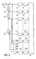
- a block constitutes an independent entity. It consists of a series of n2 groups G1, G2, .... G n 2. Each group contains a determined number of words which are either information words or redundancy words. To reduce the risk of errors, these groups are organized in frames. As an example, in the representation of FIG. 1, each group consists of a series of 8 frames T1, T2, ... T8, each frame comprising a synchronization word SY, an identification word ID noting the number of the frame in the group and the number of the group in the block, a series of 16 words M1, M2, ... M16 and an error-detecting code word. This identification word can possibly be extended to carry various information associated with the words M1 to M16 of the frame, such as a scale factor.
- This block contains 8 linked sets each formed by a series of n2-k frames of 16 information words and k frames of 16 redundancy words.
- the elements (bit, word or frame) of a linked set are distributed at the rate of one element per group, these elements occupying homologous positions in each group.
- the first n2-k groups contain for example the n2- k information words of each linked set and the last k groups the associated redundancy words.
- the number of words per frame, frames per group and groups per block depends on the transmission channel or the recording medium used. In the case where the transmission is carried out in packets, it may be advantageous to match frame and package.
- two main types of errors can occur: long errors due to large mechanical incidents affecting the magnetic tape over a length of approximately 5 to 10 mm, and short errors due to dust or a magnetic defect affecting the strip over a length of the order of a tenth of a millimeter.
- each frame has a length of the order of a tenth of a millimeter to avoid losing an entire group when there is a short error.
- FIG. 2 a mode for producing a transmission device for implementing the method of the invention.
- This device uses an extended Hamming code (16, 11) to associate 5 redundancy words with each sequence of 11 information words.
- This device includes a set of 11 shift registers 21, 22, ... 211 of N bits connected in series, a coding circuit 4 to 11 inputs each connected to an output of a shift register 21, 22, .. ., 211 and with 5 outputs, a set of 16 registers of the first input-first output type 61, 62, ... 616, the first 11 being connected as input each to one of the shift registers 21, -211 and the other 5 being connected at the input each to one of the 5 outputs of the coding circuit, a set of 16 framing means 81, 82, ... 816 each connected to one of the registers 61, 62,. .. 616 and a means of multiplexing and mixing 10.
- the device receives sequences of 11 ⁇ N bits on the input of the 21 shift register. These 11 ⁇ N bits load the shift registers 21, 22, ... 211 with N bits each.
- N is a multiple of the length n1 of the information words.
- 11 bits are available in parallel, one at the output of each register 21, 22, ... 211. These 11 bits are homologous bits, i.e. of the same rank, of 11 different information words.
- the coding circuit 4 performs, by means of a set of OU-EXCLUSIVE gates, the calculation of the 5 associated redundancy bits by Hamming coding to these 11 bits of information. These 5 redundancy bits and these 11 information bits form a set of 16 linked bits which are stored, one bit per register, in registers 61, 62, ... 616.
- the Hamming coding of the 11 information bits is represented by a Hamming matrix with 16 columns and 5 lines. This matrix is chosen according to the transmission or recording format of the blocks. By choosing a matrix whose column vectors are of odd parity, it is certain that any triplet of column vectors forms a linearly independent system. This allows at least three errors to be corrected in all cases, if the frame error detection codes have detected three erroneous frames.
- the matrix can be optimized to correct up to 5 errors relating to consecutive linked elements (up to k in the general case, where k is the number of redundancy words).
- the column vectors of the matrix can also be chosen as a function of the recording format of the block on the recording medium or of the transmission format of the block in the transmission channel.
- the column vectors such as the vectors of index i, i + P, i + 2P,. .. form a linearly independent system (or 1 i P). This ensures the correction of a track among P, for P sufficiently large.
- the coding operation is repeated N times for each of the N sets of 11 bits contained in parallel in the shift registers 21, 22, ... 211.
- the registers 61, 62, ... 616 then each contain N bits.
- Each set of N bits is transmitted to a framing means which delivers by means of a frame containing a synchronization word, a frame identification word, N information or redundancy bits and an error detecting code , for example a code word of type CRC.
- the set of 16 frames delivered by the framing means constitutes a linked set.
- the multiplexing and shuffling means 10 can form a transmission block by simply multiplexing these frames.
- the block then includes a single linked set and each of the 16 groups in the block contains a single frame.
- the means 10 is provided with storage means for storing several linked sets and mixing or interleaving means for interleaving the frames of the linked sets in order to deliver a block of which each group comprises several frames.
- the purpose of this interleaving is to geographically separate the frames of the same linked set so as to limit the probability of losing several frames of the same linked set.
- the block produced by the device of FIG. 2 and the structure of which has been described with reference to FIG. 1 is transmitted over a transmission channel or recorded on a recording medium.
- the recording medium may include one or more tracks in parallel.
- the recording medium comprises a single track
- it is analogous to a transmission channel.
- the block is recorded linearly according to the format of Figure 1.
- the recording medium is a magnetic tape
- it generally comprises several tracks in parallel.
- Each linked assembly of the block is then preferably distributed over several tracks of the magnetic strip.
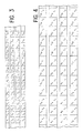
- FIG. 3 shows a recording format of 4 blocks G, H, J, K comprising respectively the groups G1 to G16, H1 to H16, J1 to J16 and K1 to K16.
- the successive groups of the same block are arranged sequentially in the longitudinal direction of the strip and with a cyclic shift of a track in the transverse direction of the strip.
- each linked set composed of 11 information words and 5 redundancy words distributed in the 16 groups of a block
- 4 words appear on each track. These words are linked to independent column vectors if the coding of each block is obtained with the matrix H indicated above.
- the 4 words of a linked set recorded on the same track can be lost simultaneously without exceeding the error correction capacity, i.e. these 4 words can be corrected by the 12 words of all linked spread over the other 3 tracks.
- the blocks G, H, J and K being independent, the coding of the invention makes it possible to correct a track of which all the information has been lost.
- the set of 4 blocks G, H, J, K has limits defined on the recording medium. This set itself constitutes a block. The structure in independent consecutive blocks on the recording medium is therefore preserved, which makes it possible to easily do electronic editing.
- the correction property is linked to the fact that the words of a linked set which are recorded on the same track are associated with vectors linearly independent of the Hamming matrix. This property can be obtained in different ways.
- Another example is to use a single block, each group of which is split into a number of frames p prime with the number of tracks on the magnetic tape and by recording successive frames in the transverse direction of the strip.
- Such a format is represented in FIG. 4 for a block of 16 groups G1 to G16 each comprising three frames T1, T2 and T3 recorded on a magnetic strip with 4 tracks.
- the 16 words forming a linked whole are divided into the 16 groups at the rate of one word per group; each word occupying a homologous position in each group is contained in a frame of the same index.
- the matrix H chosen in particular, the column column vectors (1, 5, 9, 13) are linearly independent. This makes it possible to correct in particular the frames G1T1, G5T1, G9T1 and G13T1 from the frames T1 of the other groups. More precisely, the matrix chosen and the recording format of FIG. 4 make it possible to completely correct the information of a track from the other three tracks.
- This method also makes it possible, with the matrix H chosen, to correct a large number of configurations in which any 4 or 5 bits (consecutive or not) of a linked set have been invalidated by the error detecting codes.
- Error configuration rates correctable are respectively 93% and 66% of cases for 4 and 5 errors.
- a1, a2, ... a11 the linked bits or homologous bits of information words of a linked set.
- the transmitted values a3, a4, a5, a6 and a7 have not been validated by the frame error detector codes, that is to say that they are likely to be erroneous, and note a ' 3, a'4, a'5, a'6 and a'7 the received values and (e3, e4, e5, e6, e7) the error vector.
- the correction capacity stops there; it is not possible to correct errors not detected by the frame error detector codes.
- the missing bits can be estimated by known masking techniques such as by interpolation between consecutive information words.
- this compatibility equation is not checked, the frame error detector codes have not detected all the errors. In this case, it is not possible to correct the words received.
- the erroneous bits can then be estimated by masking techniques.
- the method of the invention also makes it possible to correct an error not detected by the error detector codes in a set of linked bits, when no error has been detected by these frame error detector codes. This situation occurs when all the bits of a linked set are validated and the associated syndrome is not zero.
- the location of the error in the bits of the linked set is determined by the value of the syndrome. If the undetected error is unique, which is the most probable case, the syndrome is equal to the column vector of the matrix H whose rank is the same as that of the erroneous bit.
- the method of the invention finally makes it possible to correct an error not detected by the frame error detecting codes when a bit of the set of linked bits has been invalidated.
- the undetected erroneous bit is therefore that of rank 11.
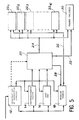
- This device comprises three circuits shown respectively in FIGS. 5 to 7.
- the circuit of FIG. 5 is a circuit for recognizing valid frames in the received frames. This circuit has a classic structure.
- the demodulation operation makes it possible to detect the frame synchronization word in the event that it is transmitted by code violation.
- Such a technique is particularly advantageous in the case of a long interruption of the received signal, as is the case when a fault affects a magnetic tape, because it allows very rapid resynchronization of the means 12 on the received frames.
- the means 12 delivers the frame identification word to an index recognition means 14, the information necessary for the detection of frame errors to a test means 16 and the N bits of the information or redundancy words to a buffer 18.
- the entry of data into the means 14, 16 and into the buffer 18 is timed by clock signals produced in a known manner by the means 12.
- the useful information bits of the frame are validated by a validation means 20 if the identification word is recognized by the means 14 and if the error detecting code indicates the absence of errors.
- the validation means can also decide to invalidate a frame based on other information which can be communicated by the means 12 such as an abnormal frame length or a code violation for the useful information bits. .
- the frame is considered as an indivisible entity as regards its validity. If the error detection code of a frame detects an error, the frame is considered invalid and all the bits of this frame are marked.
- the error detector code invalidates only the bits of the frame considered to be erroneous.
- the treatment detection and correction of errors by means of the redundancy words is then a bit-by-bit processing, that is to say that this processing affects sets of n2 bits, including n2-k of information and k of redundancy, extracted from n2 linked frames, and that this processing is repeated for each set of n2 bits which occupies a given rank in said frames.
- this treatment notably includes a matrix inversion step. It is understood that the bit by bit processing of a frame can be long. It is therefore generally preferable to validate or invalidate all the bits of the frame simultaneously. Thus, the same matrix is used for each set of n2 bits; in this case there is only one inverse matrix calculation per set of linked frames, resulting in a much higher processing speed.
- this frame processing is entirely suited to the probability of error on the recording medium since, as indicated above, the length of a frame is chosen by the same order of magnitude as short errors (about 1/10 of a millimeter) on the recording medium.
- a frame When a frame is validated, it is stored in one of the 16 memories 221, 222, ... 2216. These memories are shown separately for a better understanding. In practice, these are areas of the same working memory. These memories are addressed by an address bus 24 by the validation means 20.
- a data line 26 connects the data output of the buffer 18 to the inputs of the memories 221 to 2216; the emission of serial data on this data line is controlled by a connection 28 connecting the validation means 20 to the buffer 18.
- the addressing of the memories 221 to 2216 is done so as to store the linked frames in the same order as in the means of framing of the transmission device of FIG. 2.
- the circuit of FIG. 5 finally comprises a register 30 connected to the address bus 24. This register is emptied before a block is received by the circuit. This is achieved by the validation means 20 by a control signal sent over a connection 32. Then, for each frame received, the validation means 20 sends data to said register 30 to mark the valid frames received.
- the content of the memories associated with the invalid frames is irrelevant for the correction as long as the correction capacities are not exceeded.
- the memory loading strategy is linked to the masking methods possibly applied to the information transmitted. In the case of packet transmission, an erroneous or lost packet will be considered as an invalid frame.
- the circuit shown in FIG. 5 corresponds to the case where the signal received comes from a single transmission channel or from a recording medium with a single track. In the case, for example, of a recording medium with several tracks, it is necessary to provide for each track an assembly consisting of the means 12, 14, 16, 18 and 20.
- the memories 221 to 2216 are accessed in writing by the frame recognition circuit of FIG. 5. They are also accessed in reading by the circuit for calculating the syndrome of the Figure 6.
- a first solution consists in providing two sets of memories 221 to 2216 and two registers 30, one set being accessible in reading and the other in writing during the reception of a block, the role of the two sets being swapped after each block.
- Another solution is to use memories with several ports organized in pages, each page being assigned to the frames of a block. This solution also makes it possible to ensure the deinterlacing function when the linked frames are interlaced with other frames, as is the case in the format of FIG. 1.
- the circuit represented in FIG. 6 calculates the syndromes associated with the sets of 16 linked bits received. It compares these syndromes to zero and is able to memorize two different non-zero syndromes.
- each memory includes a single data output which is connected to an input d '' a syndrome calculation means 34 to 16 entries E1, E2, ..., E16.
- This means delivers on 5 outputs S1, S2, S3, S4 and S5 the syndrome defined by the product between the Hamming matrix H and the vector of the 16 linked bits received.
- An OR gate 36 whose inputs are connected to the outputs of the means 34 makes it possible to detect if the syndrome is zero.
- the circuit also includes two D-type flip-flops 38, 40 in series, each flip-flop containing 5 bits, flip-flop 38 being connected to the output of the means 34 by a data bus 42.
- the two flip-flops are loaded simultaneously by the output signal an AND gate 44, one input of which is connected to the output of the OR gate 36 and the other input of which is connected to the output of a comparison means 46 which delivers a signal at the high level when the syndromes delivered by the means 34 and rocker 38 are different.
- This set in which the flip-flops are initialized to zero at the start of the block, makes it possible to store the first non-zero syndrome of a block in flip-flop 38 and, when a second non-zero syndrome is detected, to shift the first syndrome flip-flop 38 to flip-flop 40 and to store the second syndrome in flip-flop 38. If a third non-zero syndrome is detected, there is a new shift in the content of flip-flops 38 and 40 and the first syndrome is lost. Generally, flip-flops 38 and 40 store the last two non-zero syndromes of a frame.
- the value of the syndrome associated with a set of linked bits and the state of validity of the frames each containing one of these linked bits makes it possible to correct the set of linked bits received in order to find the set of transmitted linked bits.
- This correction is implemented in the correction circuit, an exemplary embodiment of which is given in FIG. 7.
- the memories 221 to 2216, the register 30 and the flip-flops 38 and 40 which reproduce respectively sets of linked frames, frame validation bits and, where appropriate, non-zero syndromes have been reproduced.
- the circuit shown in Figure 7 includes a multiplexer 48 whose inputs are connected to the outputs of memories 221 to 2211 containing information bits.
- the output of this multiplexer is connected to an input of a parity operator 50 of the OU-EXCLUSIVE type.
- the data output is connected to the input of an AND gate 5212 to 5216, the output of which is applied to an input of the parity operator 50.
- the second input of each AND gate is supplied with a bit of a 5-bit mask contained in a random access memory (RAM) 54.
- RAM random access memory
- the circuit also includes a means of calculation, such as a microprocessor 56, to calculate this mask as a function of the content of the register 30 and flip-flops 38 and 40.
- the microprocessor 56 is synchronized with a sequencer 58 which ensures the selection of the data at the input of the multiplexer 48 and in the RAM 54.
- the processing carried out by the microprocessor 56 relates to a complete set of linked frames and comprises two successive stages: the search for erroneous frames not detected by the frame error detector codes, and the calculation of the correction coefficients forming the mask applied to the second inputs of AND gates 5212 to 5216.
- the microprocessor reads the content of register 30 to determine the number of invalid frames detected, that is to say the number of linked bits invalidated among the 16 bits of a linked set. If this number of invalid frames is greater than 5 (number of redundancy bits), the correction is impossible and the 11 information bits of the set of linked bits are estimated by masking techniques.
- the microprocessor examines the syndromes K1 and K2 contained in flip-flops 38 and 40 to detect a possible false frame which would not have been invalidated by its error detecting code.
- the next step consists for the microprocessor 56, in forming the matrix H ′ with c ( c 5) columns and 5 lines formed by the c column vectors associated with the c invalidated frames classified by increasing rank.
- This matrix H ' is transformed in a conventional manner, for example by triangulation, to produce a matrix H' -1 with 5 columns and 5 rows.
- the sequencer 58 simultaneously controls the multiplexer 48 and the RAM memory 54 to deliver to the parity operator 50 a bit of a frame and the associated correction word, this word being equal to the syndrome multiplied by the mask formed by the 5 coefficients correction binaries.
Landscapes
- Engineering & Computer Science (AREA)
- Multimedia (AREA)
- Signal Processing (AREA)
- Physics & Mathematics (AREA)
- Probability & Statistics with Applications (AREA)
- Theoretical Computer Science (AREA)
- Error Detection And Correction (AREA)
- Detection And Prevention Of Errors In Transmission (AREA)
- Radio Relay Systems (AREA)
- Mobile Radio Communication Systems (AREA)
- Compression, Expansion, Code Conversion, And Decoders (AREA)
- Reduction Or Emphasis Of Bandwidth Of Signals (AREA)
Claims (11)
- Verfahren zum Übertragen digitaler Information in wörterblöcken, von denen jeder eine Länge von n₁ Bits besitzt, wo n₁ eine ganze Zahl ist, wobei das verfahren darin besteht, sukzessive den zu übertragenden Informationswörtern Wörter eines Fehlerkorrekturcodes und Wörter eines Fehlerdetektorcodes hinzuzufügen; wobei in diesem Verfahren:- der Fehlerkorrekturcode ein Hammingcode ist, mittels dessen man k Redundanzwörter jeder Folge von n₂-k (n₂>k) aufeinanderfolgenden Informationswörtern hinzufügt, wobei die n₂-k Informationswörter mit den k Redundanzwörtern eine Wörteranordnung bilden, die verbundene Anordnung genannt wird, wobei jedes Redundanzwort n₁ Bits besitzt und für jeden Rang i, wobei 1≦αµρ¨i≦αµρ¨n₁, die k Bits des Rangs i der Redundanzwörter Redundanzbits der n₂-k Bits des Rangs i der n₂-k Informationswörter sind, wobei die Codierung durch eine Hammingmatrix durchgeführt wird, deren Spaltenvektoren so ausgewählt sind, daß eine Korrektur einer bestimmten Untermenge von möglichen Fehlern ermöglicht wird,- der Fehlerdetektorcode auf Folgen von Informationswörtern oder auf Folgen von Redundanzwörtern angewandt wird, wobei die Wörter einerselben Folge verschiedenen verbundenen Anordnungen angehören, wobei jeder übertragene Block eine Mehrzahl von Folgen mit n₂-k Informationswörtern und den damit verbundenen Wörtern des Fehlerdetektorcodes und des Fehlerkorrekturcodes umfaßt,dadurch gekennzeichnet, daß für ein auf einem Träger mit P parallelen Spuren aufgenommenes Signal die k Redundanzbits, die mit den n₂-k Informationsbits verbunden sind, erzeugt werden unter Verwendung einer Hammingmatrix mit n₂ Spalten und k Zeilen, von der sofort k Zeigervektoren i, i+P, i+2P,..., i+(k-1)P, wo 1,P ganze Zahlen und i+(k-1)P≦αµρ¨n₂ sind, ein linear unabhängiges System bilden, wobei jede verbundene Anordnung eines Blocks auf mehrere Spuren verteilt ist, wobei ein Codierwort so auf mehrere Spuren verteilt ist, während mehrere Elemente des Worts auf der gleichen Spur aufgenommen sind.
- Verfahren nach Anspruch 1 zur Aufnahme eines Blocks auf einen Informationsträger mit P parallelen Aufnahmespuren, dadurch gekennzeichnet, daß man die n₂ Wörter einer verbundenen Anordnung derart auf die P Spuren verteilt, daß die auf derselben Spur aufgenommenen Wörter mit Spaltenvektoren der Hammingmatrix, die ein linear unabhängiges System bilden, verbunden sind.
- Verfahren nach Anspruch 1 oder 2, dadurch gekennzeichnet, daß man nach dem Verbinden von k Redundanzwörtern mit n₂-k Informationswörtern, um eine Anordnung von verbundenen Wörtern herzustellen, die Wörter von n₃ verbundenen Anordnungen verkettet, um einen aus n₂ Gruppen bestehenden Ausgabeblock zu bilden, wobei jede Gruppe ein Wort aus jeder verbundenen Anordnung und wenigstens einen Fehlerdetektorcode enthält.
- Verfahren nach Anspruch 3, dadurch gekennzeichnet, daß die Gruppen, die Redundanzwörter enthalten, in der Blockmitte zwischen den Gruppen, die gerade Informationswörter, und den Gruppen, die ungerade Informationswörter enthalten, angeordnet sind.
- Verfahren nach einem der Ansprüche 1 bis 4, dadurch gekennzeichnet, daß jedes Wort einer verbundenen Anordnung in einem Teilbild enthalten ist, wobei jedes Teilbild ein Synchronisationswort, wenigsten ein Informationswort oder Redundanzwort und einen Fehlerdetektorcode enhält.
- Verfahren nach Anspruch 5 zur Aufnahme eines Blocks auf einen Informationsträger mit P parallelen Aufnahmespuren, wobei jede Gruppe des Blocks p Teilbilder enthält, wobei p mit der Zahl der Spuren P zuerst ist, dadurch gekennzeichnet, daß man die n₂ Wörter einer verbundenen Anordnung derart auf die P Spuren verteilt, daß die auf derselben Spur aufgenommenen Wörter mit Spaltenvektoren der Hammingmatrix, die ein linear unabhängiges System Teilbilden, verbunden sind, und daß man den Block Teilbild für Teilbild aufnimmt, wobei die Teilbilder jeder Anordnung aus p aufeinanderfolgenden Teilbildern des Blocks parallel auf den P Spuren angeordnet sind.
- Verfahren anch Anspruch 1, dadurch gekennzeichnet, daß man bei der Aufnahme die Gültigkeit jedes Informationsbits oder Redundanzbits in Verbindung mit den mit den Informationswörtern oder Redundanzwörtern verbundenen Fehlerdetektionscodes bestimmt, man für jede Anordnung aus n₂ verbundenen Bits die mit dieser Anordnung verbundene Verknüpfung berechnet, daß man von der Verknüpfung und den auf jedes Bit bezogenen Gültigkeitsinformationen einen Fehlervektor bezogen auf den verwendeten Hammingcode ableitet und daß man jeden Vektor von n₂-k empfangenen Bits durch diesen Fehlervektor korrigiert.
- Verfahren nach Anspruch 7, dadurch gekennzeichnet, daß man zum Berechnen des Fehlervektors für einen Vektor aus n₂-k verbundenen Bits eine reduzierte Matrix (H') definiert, die aus den Spaltenvektoren der bei der Ausgabe verwendeten Hammingmatrix (H) besteht, deren Ränge gleich denen der durch den Fehlerdetektionscode ungültig erklärten, verbundenen Bits sind, und daß man daraus eine weitere Matrix (H'-1, H") herleitet, so daß das Produkt dieser weiteren Matrix mit der Verknüpfung gleich dem Fehlervektor ist.
- Verfahren nach einem der Ansprüche 7 und 8, dadurch gekennzeichnet, daß man für jede Anordnung verbundener Bits die Verknüpfung verwendet, wenn sie nicht Null ist, um fehlerhafte Bits zu detektieren, die nicht durch den Fehlerdetektionscode ungültig gemacht wurden.
- Verfahren nach Anspruch 7, bei dem die Informationswörter und Redundanzwörter in Teilbildern ausgegeben werden, dadurch gekennzeichnet, daß man die Gültigkeit eines empfangenen Teilbilds in Verbindung mit seinem Fehlerdetektionscode detektiert und daß man für jede Anordnung verbundener Teilbilder eine reduzierte Matrix (H') definiert, die aus den Spaltenvektoren der bei der Ausgabe verwendeten Hammingmatrix (H) besteht, deren Ränge gleich denen der durch den Fehlerdetektionscode ungültig erklärten, verbundenen Teilbilder sind, und daß man daraus eine weitere Matrix (H'-1, H"), die für jede Anordnung von verbundenen Teilbildern eindeutig ist, herleitet, so daß das Produkt dieser weiteren Matrix mit der Verbindung gleich dem Fehlervektor ist.
- Verfahren nach Anspruch 10, dadurch gekennzeichnet, daß man wenigstens bestimmte Verknüpfungen, die nicht Null sind und mit Anordnungen von mit verbundenen Teilbildern verbundenen Bits verbunden sind, speichert, und daß man diese Verknüpfungen, die nicht Null sind, verwendet, um fehlerhafte Teilbilder zu entdecken, die nicht vom Fehlerdetektionscode ungültig gemacht wurden.
Priority Applications (1)
| Application Number | Priority Date | Filing Date | Title |
|---|---|---|---|
| AT86401185T ATE63412T1 (de) | 1985-06-05 | 1986-06-03 | Verfahren zur uebertragung von digitaler information in woerterbloecken. |
Applications Claiming Priority (2)
| Application Number | Priority Date | Filing Date | Title |
|---|---|---|---|
| FR8508481A FR2583240B1 (fr) | 1985-06-05 | 1985-06-05 | Procede de transmission en blocs de mots d'information numerique |
| FR8508481 | 1985-06-05 |
Publications (2)
| Publication Number | Publication Date |
|---|---|
| EP0204635A1 EP0204635A1 (de) | 1986-12-10 |
| EP0204635B1 true EP0204635B1 (de) | 1991-05-08 |
Family
ID=9319895
Family Applications (1)
| Application Number | Title | Priority Date | Filing Date |
|---|---|---|---|
| EP86401185A Expired - Lifetime EP0204635B1 (de) | 1985-06-05 | 1986-06-03 | Verfahren zur Übertragung von digitaler Information in Wörterblöcken |
Country Status (6)
| Country | Link |
|---|---|
| US (1) | US4744086A (de) |
| EP (1) | EP0204635B1 (de) |
| JP (1) | JPS61281722A (de) |
| AT (1) | ATE63412T1 (de) |
| DE (1) | DE3679104D1 (de) |
| FR (1) | FR2583240B1 (de) |
Cited By (2)
| Publication number | Priority date | Publication date | Assignee | Title |
|---|---|---|---|---|
| RU2108667C1 (ru) * | 1994-01-19 | 1998-04-10 | Акционерное общество "Тейвас" | Способ кодирования и декодирования данных для системы персонального радиовызова и декодер для системы персонального радиовызова |
| RU2110148C1 (ru) * | 1994-04-15 | 1998-04-27 | Акционерное общество "Тейвас" | Способ кодирования и декодирования данных для системы радиовещательной передачи цифровых сообщений |
Families Citing this family (14)
| Publication number | Priority date | Publication date | Assignee | Title |
|---|---|---|---|---|
| JPS63274222A (ja) * | 1987-05-01 | 1988-11-11 | Matsushita Electric Ind Co Ltd | インタ−リ−ブ方法 |
| US5111463A (en) * | 1989-11-09 | 1992-05-05 | Exabyte Corporation | Error correction method and apparatus |
| US5247579A (en) * | 1990-12-05 | 1993-09-21 | Digital Voice Systems, Inc. | Methods for speech transmission |
| US5392294A (en) * | 1991-03-08 | 1995-02-21 | International Business Machines Corporation | Diagnostic tool and method for locating the origin of parasitic bit faults in a memory array |
| US5517511A (en) * | 1992-11-30 | 1996-05-14 | Digital Voice Systems, Inc. | Digital transmission of acoustic signals over a noisy communication channel |
| US5481566A (en) * | 1993-12-29 | 1996-01-02 | At&T Corp. | Method and apparatus to increase efficiency of systematic codes |
| FR2717644B1 (fr) * | 1994-03-15 | 1996-04-26 | Alcatel Mobile Comm France | Procédé de codage - Entrelacement et procédé correspondant de désentrelacement - décodage. |
| DE69924261T2 (de) * | 1998-07-24 | 2006-05-18 | Thomson Multimedia | Erfassung der abtastphase |
| US6781987B1 (en) * | 1999-10-19 | 2004-08-24 | Lucent Technologies Inc. | Method for packet transmission with error detection codes |
| US6748566B1 (en) * | 2000-07-21 | 2004-06-08 | Lucent Technologies Inc. | Ensuring proper acceptance of data at a receiver in wireless multiple access communications systems |
| TWI341095B (en) * | 2007-12-12 | 2011-04-21 | Nat Univ Tsing Hua | Light-overhead and flexible wireless sensor message authentication method |
| TWI459749B (zh) | 2010-12-27 | 2014-11-01 | Ind Tech Res Inst | 數位資訊編碼方法、解碼方法、資訊傳播裝置及資訊管理裝置 |
| RU2566336C1 (ru) * | 2014-12-12 | 2015-10-20 | Российская Федерация, от имени которой выступает Государственная корпорация по атомной энергии "Росатом" | СПОСОБ ИСПРАВЛЕНИЯ ОШИБОК ПРИ ПЕРЕДАЧЕ ИНФОРМАЦИИ БИИМПУЛЬСНЫМ КОДОМ Манчестер-II И УСТРОЙСТВО ЕГО ОСУЩЕСТВЛЕНИЯ |
| US10635909B2 (en) * | 2015-12-30 | 2020-04-28 | Texas Instruments Incorporated | Vehicle control with efficient iterative triangulation |
Family Cites Families (11)
| Publication number | Priority date | Publication date | Assignee | Title |
|---|---|---|---|---|
| US3439331A (en) * | 1965-06-16 | 1969-04-15 | Ibm | Error detection and correction apparatus |
| JPS5857781B2 (ja) * | 1978-01-17 | 1983-12-21 | 三菱電機株式会社 | 符号化復号化方式 |
| JPS55120250A (en) * | 1979-03-08 | 1980-09-16 | Sony Corp | Pcm signal transmitting method |
| DE3040004A1 (de) * | 1979-10-24 | 1981-05-07 | Matsushita Electric Industrial Co., Ltd., Kadoma, Osaka | Verfahren und vorrichtung zum codieren von pruefworten geringer redundanz aus ursprungsdaten |
| JPS5898814A (ja) * | 1981-12-08 | 1983-06-11 | Sony Corp | エラ−デ−タ補間装置 |
| JPH07118159B2 (ja) * | 1982-12-06 | 1995-12-18 | ソニー株式会社 | Pcm信号記録方法 |
| JPH0661156B2 (ja) * | 1983-05-21 | 1994-08-10 | ソニー株式会社 | エラ−訂正のための符号化方法 |
| CA1243774A (en) * | 1983-06-15 | 1988-10-25 | Takaharu Noguchi | Pcm signal recording/reproducing apparatus |
| JPS6061954A (ja) * | 1983-09-14 | 1985-04-09 | Hitachi Ltd | ディジタル信号処理装置 |
| JPH0828052B2 (ja) * | 1983-06-15 | 1996-03-21 | 株式会社日立製作所 | Pcmデータのフレーム生成方法 |
| JPH07111815B2 (ja) * | 1984-07-23 | 1995-11-29 | 株式会社日立製作所 | デイジタル信号記録方式 |
-
1985
- 1985-06-05 FR FR8508481A patent/FR2583240B1/fr not_active Expired - Fee Related
-
1986
- 1986-06-03 EP EP86401185A patent/EP0204635B1/de not_active Expired - Lifetime
- 1986-06-03 AT AT86401185T patent/ATE63412T1/de not_active IP Right Cessation
- 1986-06-03 DE DE8686401185T patent/DE3679104D1/de not_active Expired - Fee Related
- 1986-06-04 US US06/870,703 patent/US4744086A/en not_active Expired - Fee Related
- 1986-06-05 JP JP61131076A patent/JPS61281722A/ja active Pending
Non-Patent Citations (1)
| Title |
|---|
| W.W. Peterson, E.J. Weldon Jr., "Error-Connecting Codes", 2e édition, 1972, pages 117-120, 131, 220, 357, 358 * |
Cited By (2)
| Publication number | Priority date | Publication date | Assignee | Title |
|---|---|---|---|---|
| RU2108667C1 (ru) * | 1994-01-19 | 1998-04-10 | Акционерное общество "Тейвас" | Способ кодирования и декодирования данных для системы персонального радиовызова и декодер для системы персонального радиовызова |
| RU2110148C1 (ru) * | 1994-04-15 | 1998-04-27 | Акционерное общество "Тейвас" | Способ кодирования и декодирования данных для системы радиовещательной передачи цифровых сообщений |
Also Published As
| Publication number | Publication date |
|---|---|
| EP0204635A1 (de) | 1986-12-10 |
| JPS61281722A (ja) | 1986-12-12 |
| US4744086A (en) | 1988-05-10 |
| DE3679104D1 (de) | 1991-06-13 |
| FR2583240A1 (fr) | 1986-12-12 |
| ATE63412T1 (de) | 1991-05-15 |
| FR2583240B1 (fr) | 1994-02-04 |
Similar Documents
| Publication | Publication Date | Title |
|---|---|---|
| EP0204635B1 (de) | Verfahren zur Übertragung von digitaler Information in Wörterblöcken | |
| EP0108655B1 (de) | System zur Erkennung und Korrektur von Übertragungsfehlern in einer binären Nachricht mit einem Fehlererkennungs- und Korrekturcode des verzahnten zyklischen Reed-Solomon-Typs | |
| EP0848501B1 (de) | System und Verfahren zur digitalen Übertragung mit einem Produktkode kombiniert mit multidimensionaler Modulation | |
| FR2467520A1 (fr) | Dispositif d'enregistrement de videodisque et dispositif decodeur de videodisque avec appareil pour la synchronisation du cadrage du mot de donnee enregistre et du tourne-videodisque sur le mot de donnee enregistre | |
| FR2546348A1 (fr) | Procede de codage de correction d'erreur | |
| CH653457A5 (fr) | Procede de correction d'erreurs dans des signaux de donnees digitales. | |
| FR2481027A1 (fr) | Procede et appareil de traitement de signaux numeriques | |
| CH646825A5 (fr) | Procedes et dispositifs d'emission et de reception d'une sequence de mots d'information numerique. | |
| FR2545298A1 (fr) | Procede de codage pour correction d'erreurs | |
| EP0436251A2 (de) | System zur Kodierung/Dekodierung von digitalen Signalen zur Übertragung und/oder Speicherung | |
| FR2550402A1 (de) | ||
| EP0821493A1 (de) | Fehlerkorrekturssystem in Datenrastern mit horizontalen und vertikalen Paritätskoden | |
| EP0848524A1 (de) | Punktierte, trelliskodierte QAM, mit iterativer Dekodierung | |
| EP1841078A1 (de) | Zweikanal Empfangsschaltkreis | |
| EP0042776A1 (de) | Echtzeit-Fehler-Korrektureinrichtung für aufgezeichnete Daten auf einem magnetischen Träger | |
| FR2673341A1 (fr) | Agencement de circuit pour detecter et corriger des defauts dans des mots de donnees. | |
| FR2540690A1 (fr) | Verificateur de codeur | |
| FR2845220A1 (fr) | Procedes et dispositifs pour le decodage des codes de geometrie algebrique a un point | |
| EP1076933B1 (de) | Vorrichtung zur berichtigung von fehlern und optischer plattenspieler, der eine solche vorrichtung einschliesst | |
| EP0350368B1 (de) | Datenkodierung und Formungsvorrichtung für ein Aufzeichnungsgerät mit drehenden Köpfen | |
| FR2776115A1 (fr) | Dispositif de correction d'erreurs et lecteur de disque optique comportant un tel dispositif | |
| FR2703551A1 (fr) | Procédé et dispositif de traitement de données d'image pour enregistrer vidéo numérique à bande. | |
| FR2900294A1 (fr) | Chargement de la memoire d'entree d'un decodeur ldpc avec des donnees a decoder | |
| EP0010506B1 (de) | Verfahren und Vorrichtungen zur binären Codierung und Decodierung für die Aufzeichnung von Audio-Signalen mit einem Fernsehsignal, insbesondere auf eine Videoplatte | |
| EP0982866B1 (de) | Verfahren zur Faltungskodierung und Uebertragung von digitalen Datenpaketen, Gerät und Verfahren zur entsprechenden Dekodierung |
Legal Events
| Date | Code | Title | Description |
|---|---|---|---|
| PUAI | Public reference made under article 153(3) epc to a published international application that has entered the european phase |
Free format text: ORIGINAL CODE: 0009012 |
|
| AK | Designated contracting states |
Kind code of ref document: A1 Designated state(s): AT BE CH DE GB IT LI LU NL SE |
|
| 17P | Request for examination filed |
Effective date: 19870509 |
|
| 17Q | First examination report despatched |
Effective date: 19890208 |
|
| GRAA | (expected) grant |
Free format text: ORIGINAL CODE: 0009210 |
|
| AK | Designated contracting states |
Kind code of ref document: B1 Designated state(s): AT BE CH DE GB IT LI LU NL SE |
|
| REF | Corresponds to: |
Ref document number: 63412 Country of ref document: AT Date of ref document: 19910515 Kind code of ref document: T |
|
| REF | Corresponds to: |
Ref document number: 3679104 Country of ref document: DE Date of ref document: 19910613 |
|
| ITF | It: translation for a ep patent filed | ||
| GBT | Gb: translation of ep patent filed (gb section 77(6)(a)/1977) | ||
| PLBE | No opposition filed within time limit |
Free format text: ORIGINAL CODE: 0009261 |
|
| STAA | Information on the status of an ep patent application or granted ep patent |
Free format text: STATUS: NO OPPOSITION FILED WITHIN TIME LIMIT |
|
| 26N | No opposition filed | ||
| EPTA | Lu: last paid annual fee | ||
| EAL | Se: european patent in force in sweden |
Ref document number: 86401185.3 |
|
| PGFP | Annual fee paid to national office [announced via postgrant information from national office to epo] |
Ref country code: GB Payment date: 19950526 Year of fee payment: 10 |
|
| PGFP | Annual fee paid to national office [announced via postgrant information from national office to epo] |
Ref country code: SE Payment date: 19950530 Year of fee payment: 10 |
|
| PGFP | Annual fee paid to national office [announced via postgrant information from national office to epo] |
Ref country code: LU Payment date: 19950601 Year of fee payment: 10 |
|
| PGFP | Annual fee paid to national office [announced via postgrant information from national office to epo] |
Ref country code: BE Payment date: 19950607 Year of fee payment: 10 |
|
| PGFP | Annual fee paid to national office [announced via postgrant information from national office to epo] |
Ref country code: CH Payment date: 19950609 Year of fee payment: 10 |
|
| PGFP | Annual fee paid to national office [announced via postgrant information from national office to epo] |
Ref country code: DE Payment date: 19950614 Year of fee payment: 10 Ref country code: AT Payment date: 19950614 Year of fee payment: 10 |
|
| PGFP | Annual fee paid to national office [announced via postgrant information from national office to epo] |
Ref country code: NL Payment date: 19950727 Year of fee payment: 10 |
|
| PG25 | Lapsed in a contracting state [announced via postgrant information from national office to epo] |
Ref country code: LU Free format text: LAPSE BECAUSE OF NON-PAYMENT OF DUE FEES Effective date: 19960603 Ref country code: GB Effective date: 19960603 Ref country code: AT Effective date: 19960603 |
|
| PG25 | Lapsed in a contracting state [announced via postgrant information from national office to epo] |
Ref country code: SE Effective date: 19960604 |
|
| PG25 | Lapsed in a contracting state [announced via postgrant information from national office to epo] |
Ref country code: LI Effective date: 19960630 Ref country code: CH Effective date: 19960630 Ref country code: BE Effective date: 19960630 |
|
| BERE | Be: lapsed |
Owner name: TELEDIFFUSIONDE FRANCE Effective date: 19960630 |
|
| PG25 | Lapsed in a contracting state [announced via postgrant information from national office to epo] |
Ref country code: NL Effective date: 19970101 |
|
| GBPC | Gb: european patent ceased through non-payment of renewal fee |
Effective date: 19960603 |
|
| REG | Reference to a national code |
Ref country code: CH Ref legal event code: PL |
|
| PG25 | Lapsed in a contracting state [announced via postgrant information from national office to epo] |
Ref country code: DE Effective date: 19970301 |
|
| EUG | Se: european patent has lapsed |
Ref document number: 86401185.3 |
|
| NLV4 | Nl: lapsed or anulled due to non-payment of the annual fee |
Effective date: 19970101 |
|
| PG25 | Lapsed in a contracting state [announced via postgrant information from national office to epo] |
Ref country code: IT Free format text: LAPSE BECAUSE OF NON-PAYMENT OF DUE FEES Effective date: 20050603 |