EP0204635B1 - Method for transmitting digital information in word blocks - Google Patents
Method for transmitting digital information in word blocks Download PDFInfo
- Publication number
- EP0204635B1 EP0204635B1 EP86401185A EP86401185A EP0204635B1 EP 0204635 B1 EP0204635 B1 EP 0204635B1 EP 86401185 A EP86401185 A EP 86401185A EP 86401185 A EP86401185 A EP 86401185A EP 0204635 B1 EP0204635 B1 EP 0204635B1
- Authority
- EP
- European Patent Office
- Prior art keywords
- words
- bits
- linked
- information
- redundancy
- Prior art date
- Legal status (The legal status is an assumption and is not a legal conclusion. Google has not performed a legal analysis and makes no representation as to the accuracy of the status listed.)
- Expired - Lifetime
Links
- 238000000034 method Methods 0.000 title claims abstract description 58
- 230000005540 biological transmission Effects 0.000 claims abstract description 31
- 208000011580 syndromic disease Diseases 0.000 claims description 92
- 239000011159 matrix material Substances 0.000 claims description 54
- 239000013598 vector Substances 0.000 claims description 46
- 238000001514 detection method Methods 0.000 claims description 10
- 230000015654 memory Effects 0.000 description 19
- 238000004364 calculation method Methods 0.000 description 8
- 238000010200 validation analysis Methods 0.000 description 7
- 230000000873 masking effect Effects 0.000 description 5
- 238000009432 framing Methods 0.000 description 4
- 230000006870 function Effects 0.000 description 4
- 230000000875 corresponding effect Effects 0.000 description 2
- 230000005236 sound signal Effects 0.000 description 2
- 101100422780 Caenorhabditis elegans sur-5 gene Proteins 0.000 description 1
- 230000002159 abnormal effect Effects 0.000 description 1
- 230000002596 correlated effect Effects 0.000 description 1
- 125000004122 cyclic group Chemical group 0.000 description 1
- 230000007547 defect Effects 0.000 description 1
- 230000009977 dual effect Effects 0.000 description 1
- 239000000428 dust Substances 0.000 description 1
- 235000021183 entrée Nutrition 0.000 description 1
- 238000000605 extraction Methods 0.000 description 1
- 230000000737 periodic effect Effects 0.000 description 1
- 238000004904 shortening Methods 0.000 description 1
- 230000001360 synchronised effect Effects 0.000 description 1
- 230000003936 working memory Effects 0.000 description 1
Images


Classifications
-
- G—PHYSICS
- G11—INFORMATION STORAGE
- G11B—INFORMATION STORAGE BASED ON RELATIVE MOVEMENT BETWEEN RECORD CARRIER AND TRANSDUCER
- G11B20/00—Signal processing not specific to the method of recording or reproducing; Circuits therefor
- G11B20/10—Digital recording or reproducing
- G11B20/18—Error detection or correction; Testing, e.g. of drop-outs
- G11B20/1806—Pulse code modulation systems for audio signals
- G11B20/1809—Pulse code modulation systems for audio signals by interleaving
-
- H—ELECTRICITY
- H03—ELECTRONIC CIRCUITRY
- H03M—CODING; DECODING; CODE CONVERSION IN GENERAL
- H03M13/00—Coding, decoding or code conversion, for error detection or error correction; Coding theory basic assumptions; Coding bounds; Error probability evaluation methods; Channel models; Simulation or testing of codes
- H03M13/03—Error detection or forward error correction by redundancy in data representation, i.e. code words containing more digits than the source words
- H03M13/05—Error detection or forward error correction by redundancy in data representation, i.e. code words containing more digits than the source words using block codes, i.e. a predetermined number of check bits joined to a predetermined number of information bits
- H03M13/13—Linear codes
Definitions
- the present invention relates to a method of transmitting digital information word blocks. It relates more particularly to a coding and decoding technique in which transmission blocks are formed each composed of a series of digital information words and associated redundancy words, these redundancy words being constructed so as to detect and to correct, upon reception, packets of errors of great length, such as those encountered in digital recording on magnetic tape.
- the information to be recorded is organized in frames each comprising a synchronization word, an identification word, one or more information words and a detector code d 'fault.
- This error detecting code may not detect all errors.
- the information words are separated into a sequence of even information words and a sequence of odd information words. These sequences are coded and transmitted with a time offset.
- This technique avoids that a fault affecting the transmission channel, or the recording medium, causes an error on two consecutive information words. An incorrectly recognized information word can thus be corrected or, if correction is not possible, interpolated from the previous information word and the next information word. This interpolation obviously has a meaning only if the successive information words are correlated, which is in particular the case in digital recording of a sound signal.
- the transmission or recording format has a sliding structure, that is to say that the interlacing of the frames is such that it is impossible to define independent blocks as is the case in article cited.
- the object of the invention is in particular to remedy the drawbacks of known transmission methods and for objective a method of transmission in independent blocks, in order to be able to make mounting easily, in particular electronic mounting.
- Another object of the invention is a transmission method capable of withstanding a loss of information occurring over the entire width of a magnetic tape over a length of approximately 5 to 10 mm, in the case where the recording is carried out in parallel on several magnetic tracks, and suitable for resist the complete loss of a magnetic strip when the information is distributed for example on four magnetic tracks.
- Another object of the invention is a transmission method making it possible to correct at least three errors, that is to say a transmission method in which the probability of non-correctable error is proportional to p4, when the probability of having an error is equal to p.
- the invention finally aims to detect and correct errors not detected by the error detector codes protecting the information and redundancy words.
- the redundancy words are preferably obtained by an extended Hamming code, that is to say of the form (2 m , 2 m -m-1), where m is an integer. But it is also possible to use a normal Hamming code of the form (2 m -1, 2 m -m-1). In both cases, the code can be shortened. It is then respectively of the form (2 m -p, 2 m -m-1-p) or of the form 2 m -1-p, 2 m -m-1-p). This shortening consists in forcing the value of p bits of each information word to a particular binary value, in general the value "0".
- a transmitted block comprises several interleaved linked sets.
- the homologous words in each set form a group.
- These homologous words are distributed in one or more frames each provided with an error detecting code, for example a code word of the CRC type.
- a Hamming matrix with n2 columns and k rows is used, all the column vectors of which are of odd parity.
- the Hamming code does not allow all errors to be corrected, unlike the Reed-Solomon code generally used. However, it has the advantage over this latter of a simpler decoding, which is important if this decoding must be done in real time.
- the Hamming matrix is chosen according to the errors that one wishes to be able to correct.
- a Hamming matrix is chosen of which any sequence of k consecutive column vectors forms a linearly independent system.
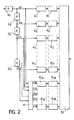
- a block constitutes an independent entity. It consists of a series of n2 groups G1, G2, .... G n 2. Each group contains a determined number of words which are either information words or redundancy words. To reduce the risk of errors, these groups are organized in frames. As an example, in the representation of FIG. 1, each group consists of a series of 8 frames T1, T2, ... T8, each frame comprising a synchronization word SY, an identification word ID noting the number of the frame in the group and the number of the group in the block, a series of 16 words M1, M2, ... M16 and an error-detecting code word. This identification word can possibly be extended to carry various information associated with the words M1 to M16 of the frame, such as a scale factor.
- This block contains 8 linked sets each formed by a series of n2-k frames of 16 information words and k frames of 16 redundancy words.
- the elements (bit, word or frame) of a linked set are distributed at the rate of one element per group, these elements occupying homologous positions in each group.
- the first n2-k groups contain for example the n2- k information words of each linked set and the last k groups the associated redundancy words.
- the number of words per frame, frames per group and groups per block depends on the transmission channel or the recording medium used. In the case where the transmission is carried out in packets, it may be advantageous to match frame and package.
- two main types of errors can occur: long errors due to large mechanical incidents affecting the magnetic tape over a length of approximately 5 to 10 mm, and short errors due to dust or a magnetic defect affecting the strip over a length of the order of a tenth of a millimeter.
- each frame has a length of the order of a tenth of a millimeter to avoid losing an entire group when there is a short error.
- FIG. 2 a mode for producing a transmission device for implementing the method of the invention.
- This device uses an extended Hamming code (16, 11) to associate 5 redundancy words with each sequence of 11 information words.
- This device includes a set of 11 shift registers 21, 22, ... 211 of N bits connected in series, a coding circuit 4 to 11 inputs each connected to an output of a shift register 21, 22, .. ., 211 and with 5 outputs, a set of 16 registers of the first input-first output type 61, 62, ... 616, the first 11 being connected as input each to one of the shift registers 21, -211 and the other 5 being connected at the input each to one of the 5 outputs of the coding circuit, a set of 16 framing means 81, 82, ... 816 each connected to one of the registers 61, 62,. .. 616 and a means of multiplexing and mixing 10.
- the device receives sequences of 11 ⁇ N bits on the input of the 21 shift register. These 11 ⁇ N bits load the shift registers 21, 22, ... 211 with N bits each.
- N is a multiple of the length n1 of the information words.
- 11 bits are available in parallel, one at the output of each register 21, 22, ... 211. These 11 bits are homologous bits, i.e. of the same rank, of 11 different information words.
- the coding circuit 4 performs, by means of a set of OU-EXCLUSIVE gates, the calculation of the 5 associated redundancy bits by Hamming coding to these 11 bits of information. These 5 redundancy bits and these 11 information bits form a set of 16 linked bits which are stored, one bit per register, in registers 61, 62, ... 616.
- the Hamming coding of the 11 information bits is represented by a Hamming matrix with 16 columns and 5 lines. This matrix is chosen according to the transmission or recording format of the blocks. By choosing a matrix whose column vectors are of odd parity, it is certain that any triplet of column vectors forms a linearly independent system. This allows at least three errors to be corrected in all cases, if the frame error detection codes have detected three erroneous frames.
- the matrix can be optimized to correct up to 5 errors relating to consecutive linked elements (up to k in the general case, where k is the number of redundancy words).
- the column vectors of the matrix can also be chosen as a function of the recording format of the block on the recording medium or of the transmission format of the block in the transmission channel.
- the column vectors such as the vectors of index i, i + P, i + 2P,. .. form a linearly independent system (or 1 i P). This ensures the correction of a track among P, for P sufficiently large.
- the coding operation is repeated N times for each of the N sets of 11 bits contained in parallel in the shift registers 21, 22, ... 211.
- the registers 61, 62, ... 616 then each contain N bits.
- Each set of N bits is transmitted to a framing means which delivers by means of a frame containing a synchronization word, a frame identification word, N information or redundancy bits and an error detecting code , for example a code word of type CRC.
- the set of 16 frames delivered by the framing means constitutes a linked set.
- the multiplexing and shuffling means 10 can form a transmission block by simply multiplexing these frames.
- the block then includes a single linked set and each of the 16 groups in the block contains a single frame.
- the means 10 is provided with storage means for storing several linked sets and mixing or interleaving means for interleaving the frames of the linked sets in order to deliver a block of which each group comprises several frames.
- the purpose of this interleaving is to geographically separate the frames of the same linked set so as to limit the probability of losing several frames of the same linked set.
- the block produced by the device of FIG. 2 and the structure of which has been described with reference to FIG. 1 is transmitted over a transmission channel or recorded on a recording medium.
- the recording medium may include one or more tracks in parallel.
- the recording medium comprises a single track
- it is analogous to a transmission channel.
- the block is recorded linearly according to the format of Figure 1.
- the recording medium is a magnetic tape
- it generally comprises several tracks in parallel.
- Each linked assembly of the block is then preferably distributed over several tracks of the magnetic strip.
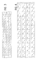
- FIG. 3 shows a recording format of 4 blocks G, H, J, K comprising respectively the groups G1 to G16, H1 to H16, J1 to J16 and K1 to K16.
- the successive groups of the same block are arranged sequentially in the longitudinal direction of the strip and with a cyclic shift of a track in the transverse direction of the strip.
- each linked set composed of 11 information words and 5 redundancy words distributed in the 16 groups of a block
- 4 words appear on each track. These words are linked to independent column vectors if the coding of each block is obtained with the matrix H indicated above.
- the 4 words of a linked set recorded on the same track can be lost simultaneously without exceeding the error correction capacity, i.e. these 4 words can be corrected by the 12 words of all linked spread over the other 3 tracks.
- the blocks G, H, J and K being independent, the coding of the invention makes it possible to correct a track of which all the information has been lost.
- the set of 4 blocks G, H, J, K has limits defined on the recording medium. This set itself constitutes a block. The structure in independent consecutive blocks on the recording medium is therefore preserved, which makes it possible to easily do electronic editing.
- the correction property is linked to the fact that the words of a linked set which are recorded on the same track are associated with vectors linearly independent of the Hamming matrix. This property can be obtained in different ways.
- Another example is to use a single block, each group of which is split into a number of frames p prime with the number of tracks on the magnetic tape and by recording successive frames in the transverse direction of the strip.
- Such a format is represented in FIG. 4 for a block of 16 groups G1 to G16 each comprising three frames T1, T2 and T3 recorded on a magnetic strip with 4 tracks.
- the 16 words forming a linked whole are divided into the 16 groups at the rate of one word per group; each word occupying a homologous position in each group is contained in a frame of the same index.
- the matrix H chosen in particular, the column column vectors (1, 5, 9, 13) are linearly independent. This makes it possible to correct in particular the frames G1T1, G5T1, G9T1 and G13T1 from the frames T1 of the other groups. More precisely, the matrix chosen and the recording format of FIG. 4 make it possible to completely correct the information of a track from the other three tracks.
- This method also makes it possible, with the matrix H chosen, to correct a large number of configurations in which any 4 or 5 bits (consecutive or not) of a linked set have been invalidated by the error detecting codes.
- Error configuration rates correctable are respectively 93% and 66% of cases for 4 and 5 errors.
- a1, a2, ... a11 the linked bits or homologous bits of information words of a linked set.
- the transmitted values a3, a4, a5, a6 and a7 have not been validated by the frame error detector codes, that is to say that they are likely to be erroneous, and note a ' 3, a'4, a'5, a'6 and a'7 the received values and (e3, e4, e5, e6, e7) the error vector.
- the correction capacity stops there; it is not possible to correct errors not detected by the frame error detector codes.
- the missing bits can be estimated by known masking techniques such as by interpolation between consecutive information words.
- this compatibility equation is not checked, the frame error detector codes have not detected all the errors. In this case, it is not possible to correct the words received.
- the erroneous bits can then be estimated by masking techniques.
- the method of the invention also makes it possible to correct an error not detected by the error detector codes in a set of linked bits, when no error has been detected by these frame error detector codes. This situation occurs when all the bits of a linked set are validated and the associated syndrome is not zero.
- the location of the error in the bits of the linked set is determined by the value of the syndrome. If the undetected error is unique, which is the most probable case, the syndrome is equal to the column vector of the matrix H whose rank is the same as that of the erroneous bit.
- the method of the invention finally makes it possible to correct an error not detected by the frame error detecting codes when a bit of the set of linked bits has been invalidated.
- the undetected erroneous bit is therefore that of rank 11.
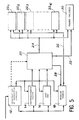
- This device comprises three circuits shown respectively in FIGS. 5 to 7.
- the circuit of FIG. 5 is a circuit for recognizing valid frames in the received frames. This circuit has a classic structure.
- the demodulation operation makes it possible to detect the frame synchronization word in the event that it is transmitted by code violation.
- Such a technique is particularly advantageous in the case of a long interruption of the received signal, as is the case when a fault affects a magnetic tape, because it allows very rapid resynchronization of the means 12 on the received frames.
- the means 12 delivers the frame identification word to an index recognition means 14, the information necessary for the detection of frame errors to a test means 16 and the N bits of the information or redundancy words to a buffer 18.
- the entry of data into the means 14, 16 and into the buffer 18 is timed by clock signals produced in a known manner by the means 12.
- the useful information bits of the frame are validated by a validation means 20 if the identification word is recognized by the means 14 and if the error detecting code indicates the absence of errors.
- the validation means can also decide to invalidate a frame based on other information which can be communicated by the means 12 such as an abnormal frame length or a code violation for the useful information bits. .
- the frame is considered as an indivisible entity as regards its validity. If the error detection code of a frame detects an error, the frame is considered invalid and all the bits of this frame are marked.
- the error detector code invalidates only the bits of the frame considered to be erroneous.
- the treatment detection and correction of errors by means of the redundancy words is then a bit-by-bit processing, that is to say that this processing affects sets of n2 bits, including n2-k of information and k of redundancy, extracted from n2 linked frames, and that this processing is repeated for each set of n2 bits which occupies a given rank in said frames.
- this treatment notably includes a matrix inversion step. It is understood that the bit by bit processing of a frame can be long. It is therefore generally preferable to validate or invalidate all the bits of the frame simultaneously. Thus, the same matrix is used for each set of n2 bits; in this case there is only one inverse matrix calculation per set of linked frames, resulting in a much higher processing speed.
- this frame processing is entirely suited to the probability of error on the recording medium since, as indicated above, the length of a frame is chosen by the same order of magnitude as short errors (about 1/10 of a millimeter) on the recording medium.
- a frame When a frame is validated, it is stored in one of the 16 memories 221, 222, ... 2216. These memories are shown separately for a better understanding. In practice, these are areas of the same working memory. These memories are addressed by an address bus 24 by the validation means 20.
- a data line 26 connects the data output of the buffer 18 to the inputs of the memories 221 to 2216; the emission of serial data on this data line is controlled by a connection 28 connecting the validation means 20 to the buffer 18.
- the addressing of the memories 221 to 2216 is done so as to store the linked frames in the same order as in the means of framing of the transmission device of FIG. 2.
- the circuit of FIG. 5 finally comprises a register 30 connected to the address bus 24. This register is emptied before a block is received by the circuit. This is achieved by the validation means 20 by a control signal sent over a connection 32. Then, for each frame received, the validation means 20 sends data to said register 30 to mark the valid frames received.
- the content of the memories associated with the invalid frames is irrelevant for the correction as long as the correction capacities are not exceeded.
- the memory loading strategy is linked to the masking methods possibly applied to the information transmitted. In the case of packet transmission, an erroneous or lost packet will be considered as an invalid frame.
- the circuit shown in FIG. 5 corresponds to the case where the signal received comes from a single transmission channel or from a recording medium with a single track. In the case, for example, of a recording medium with several tracks, it is necessary to provide for each track an assembly consisting of the means 12, 14, 16, 18 and 20.
- the memories 221 to 2216 are accessed in writing by the frame recognition circuit of FIG. 5. They are also accessed in reading by the circuit for calculating the syndrome of the Figure 6.
- a first solution consists in providing two sets of memories 221 to 2216 and two registers 30, one set being accessible in reading and the other in writing during the reception of a block, the role of the two sets being swapped after each block.
- Another solution is to use memories with several ports organized in pages, each page being assigned to the frames of a block. This solution also makes it possible to ensure the deinterlacing function when the linked frames are interlaced with other frames, as is the case in the format of FIG. 1.
- the circuit represented in FIG. 6 calculates the syndromes associated with the sets of 16 linked bits received. It compares these syndromes to zero and is able to memorize two different non-zero syndromes.
- each memory includes a single data output which is connected to an input d '' a syndrome calculation means 34 to 16 entries E1, E2, ..., E16.
- This means delivers on 5 outputs S1, S2, S3, S4 and S5 the syndrome defined by the product between the Hamming matrix H and the vector of the 16 linked bits received.
- An OR gate 36 whose inputs are connected to the outputs of the means 34 makes it possible to detect if the syndrome is zero.
- the circuit also includes two D-type flip-flops 38, 40 in series, each flip-flop containing 5 bits, flip-flop 38 being connected to the output of the means 34 by a data bus 42.
- the two flip-flops are loaded simultaneously by the output signal an AND gate 44, one input of which is connected to the output of the OR gate 36 and the other input of which is connected to the output of a comparison means 46 which delivers a signal at the high level when the syndromes delivered by the means 34 and rocker 38 are different.
- This set in which the flip-flops are initialized to zero at the start of the block, makes it possible to store the first non-zero syndrome of a block in flip-flop 38 and, when a second non-zero syndrome is detected, to shift the first syndrome flip-flop 38 to flip-flop 40 and to store the second syndrome in flip-flop 38. If a third non-zero syndrome is detected, there is a new shift in the content of flip-flops 38 and 40 and the first syndrome is lost. Generally, flip-flops 38 and 40 store the last two non-zero syndromes of a frame.
- the value of the syndrome associated with a set of linked bits and the state of validity of the frames each containing one of these linked bits makes it possible to correct the set of linked bits received in order to find the set of transmitted linked bits.
- This correction is implemented in the correction circuit, an exemplary embodiment of which is given in FIG. 7.
- the memories 221 to 2216, the register 30 and the flip-flops 38 and 40 which reproduce respectively sets of linked frames, frame validation bits and, where appropriate, non-zero syndromes have been reproduced.
- the circuit shown in Figure 7 includes a multiplexer 48 whose inputs are connected to the outputs of memories 221 to 2211 containing information bits.
- the output of this multiplexer is connected to an input of a parity operator 50 of the OU-EXCLUSIVE type.
- the data output is connected to the input of an AND gate 5212 to 5216, the output of which is applied to an input of the parity operator 50.
- the second input of each AND gate is supplied with a bit of a 5-bit mask contained in a random access memory (RAM) 54.
- RAM random access memory
- the circuit also includes a means of calculation, such as a microprocessor 56, to calculate this mask as a function of the content of the register 30 and flip-flops 38 and 40.
- the microprocessor 56 is synchronized with a sequencer 58 which ensures the selection of the data at the input of the multiplexer 48 and in the RAM 54.
- the processing carried out by the microprocessor 56 relates to a complete set of linked frames and comprises two successive stages: the search for erroneous frames not detected by the frame error detector codes, and the calculation of the correction coefficients forming the mask applied to the second inputs of AND gates 5212 to 5216.
- the microprocessor reads the content of register 30 to determine the number of invalid frames detected, that is to say the number of linked bits invalidated among the 16 bits of a linked set. If this number of invalid frames is greater than 5 (number of redundancy bits), the correction is impossible and the 11 information bits of the set of linked bits are estimated by masking techniques.
- the microprocessor examines the syndromes K1 and K2 contained in flip-flops 38 and 40 to detect a possible false frame which would not have been invalidated by its error detecting code.
- the next step consists for the microprocessor 56, in forming the matrix H ′ with c ( c 5) columns and 5 lines formed by the c column vectors associated with the c invalidated frames classified by increasing rank.
- This matrix H ' is transformed in a conventional manner, for example by triangulation, to produce a matrix H' -1 with 5 columns and 5 rows.
- the sequencer 58 simultaneously controls the multiplexer 48 and the RAM memory 54 to deliver to the parity operator 50 a bit of a frame and the associated correction word, this word being equal to the syndrome multiplied by the mask formed by the 5 coefficients correction binaries.
Landscapes
- Engineering & Computer Science (AREA)
- Multimedia (AREA)
- Signal Processing (AREA)
- Physics & Mathematics (AREA)
- Probability & Statistics with Applications (AREA)
- Theoretical Computer Science (AREA)
- Error Detection And Correction (AREA)
- Detection And Prevention Of Errors In Transmission (AREA)
- Radio Relay Systems (AREA)
- Mobile Radio Communication Systems (AREA)
- Compression, Expansion, Code Conversion, And Decoders (AREA)
- Reduction Or Emphasis Of Bandwidth Of Signals (AREA)
Abstract
Description
La présente invention a pour objet un procédé de transmission en blocs de mots d'information numérique. Elle concerne plus particulièrement une technique de codage et de décodage dans laquelle on forme des blocs d'émission composés chacun d'une suite de mots d'information numérique et de mots de redondance associés, ces mots de redondance étant construits de manière à détecter et à corriger, à la réception, des paquets d'erreurs de grande longueur, telles que celles rencontrées en enregistrement numérique sur bande magnétique.The present invention relates to a method of transmitting digital information word blocks. It relates more particularly to a coding and decoding technique in which transmission blocks are formed each composed of a series of digital information words and associated redundancy words, these redundancy words being constructed so as to detect and to correct, upon reception, packets of errors of great length, such as those encountered in digital recording on magnetic tape.
De manière classique, dans le domaine de l'enregistrement numérique sur bande magnétique, l'information à enregistrer est organisée en trames comprenant chacune un mot de synchronisation, un mot d'identification, un ou plusieurs mots d'information et un code détecteur d'erreur. Ce code détecteur d'erreur peut ne pas détecter toutes les erreurs.Conventionally, in the field of digital recording on magnetic tape, the information to be recorded is organized in frames each comprising a synchronization word, an identification word, one or more information words and a detector code d 'fault. This error detecting code may not detect all errors.
Pour améliorer les capacités de détection et de correction des erreurs, il est connu de regrouper les trames en ensembles de trames et de relier les informations homologues (i.e. les bits de même rang) des trames d'un même ensemble par des relations mathématiques simples telles que la parité de la somme des bits homologues. Il est également connu de former un bloc d'émission en entrelaçant les suites de trames de plusieurs ensembles liés de façon à rendre les probabilités d'erreurs sur les trames d'un même ensemble indépendantes les unes des autres.To improve the detection and correction capabilities of errors, it is known to group the frames into sets of frames and to link the homologous information (ie the bits of the same rank) of the frames of the same set by simple mathematical relationships such as than the parity of the sum of the homologous bits. It is also known to form a transmission block by interleaving the series of frames from several linked sets so as to make the probabilities of errors on the frames of the same set independent of each other.
L'article "Improved two channel PCM tape recorder for professional use" de K. Tanaka et al présenté au 64ème congrès de la Société des Ingénieurs Audio, New-York,Novembre 1979 décrit un tel procédé de transmission en blocs de mots d'information numérique. L'enregistrement est réalisé sur une bande magnétique à 8 pistes dont 6 sont affectées aux mots d'information et 2 aux mots de redondance reliant les informations homologues des trames d'un même ensemble. Ces mots de redondance sont obtenus à l'aide d'un code du type Reed-Solomon.The article "Improved two channel PCM tape recorder for professional use" by K. Tanaka et al presented at the 64th congress of the Society of Audio Engineers, New York, November 1979 describes such a method of transmission in blocks of information words digital. The recording is carried out on a magnetic strip with 8 tracks, 6 of which are assigned to the information words and 2 to the redundancy words connecting the homologous information of the frames of the same set. These redundancy words are obtained using a code of the Reed-Solomon type.
Ce procédé connu n'est pas pleinement satisfaisant car le code de Reed-Solomon est un code complexe. La détection et la correction des erreurs au moyen de ce code demandent donc des calculs longs et compliqués. Par ailleurs, la capacité de correction du procédé décrit, c'est-à-dire la probabilité d'avoir une erreur non corrigeable, est proportionnelle à p³ lorsque la probabilité d'avoir une erreur est égale à p. Cette capacité de correction n'est pas très élevée. Le rapport performance à complexité apparaît donc très moyen.This known method is not fully satisfactory because the Reed-Solomon code is a complex code. Detecting and correcting errors using this code therefore requires long and complicated calculations. Furthermore, the correction capacity of the process described, that is to say the probability of having an uncorrectable error, is proportional to p³ when the probability of having an error is equal to p. This correction capacity is not very high. The performance to complexity ratio therefore appears very average.
On connait des procédés de transmission dans lesquels la probabilité d'erreur non corrigeable est proportionnelle à p⁴. Un tel procédé est décrit dans la demande de brevet français n°2 467 510 intitulée "Procédé et dispositif de transmission d'une séquence de mots d'information numérique".Transmission methods are known in which the probability of error which cannot be corrected is proportional to p⁴. Such a method is described in French patent application No. 2,467,510 entitled "Method and device for transmitting a sequence of digital information words".
Dans ce procédé, les mots d'information sont séparés en une séquence de mots d'informatíon pairs et une séquence de mots d'information impairs. Ces séquences sont codées et transmises avec un décalage temporel. Cette technique permet d'éviter qu'un défaut affectant le canal de transmission, ou le support d'enregistrement, ne provoque une erreur sur deux mots d'information consécutifs. Un mot d'information reconnu erroné peut ainsi être corrigé ou, si la correction n'est pas possible, interpolé à partir du mot d'information précédent et du mot d'information suivant. Cette interpolation n'a évidemment un sens que si les mots d' information successifs sont corrélés, ce qui est notamment le cas en enregistrement numérique d'un signal sonore.In this method, the information words are separated into a sequence of even information words and a sequence of odd information words. These sequences are coded and transmitted with a time offset. This technique avoids that a fault affecting the transmission channel, or the recording medium, causes an error on two consecutive information words. An incorrectly recognized information word can thus be corrected or, if correction is not possible, interpolated from the previous information word and the next information word. This interpolation obviously has a meaning only if the successive information words are correlated, which is in particular the case in digital recording of a sound signal.
Dans ce procédé, le format de transmission ou d'enregistrement présente une structure glissante c'est-à-dire que l'entrelacement des trames est tel qu'il est impossible de définir des blocs indépendants comme c'est le cas dans l'article cité. Ceci a pour conséquence une complication lors du montage électronique de programmes sonores, notamment due au fait que les structures glissantes sont brisées au point de montage, ce qui induit une perte de capacité de correction.In this method, the transmission or recording format has a sliding structure, that is to say that the interlacing of the frames is such that it is impossible to define independent blocks as is the case in article cited. This results in a complication during electronic editing of sound programs, in particular due to the fact that the sliding structures are broken at the mounting point, which induces a loss of correction capacity.
D'autre part, on pourra se reporter au document "IBM Technical Disclosure Bulletin", vol. 17, No 2, dans lequel est décrit un procédé de codage utilisant un code correcteur d'erreur et un code détecteur d'erreur.On the other hand, reference may be made to the document "IBM Technical Disclosure Bulletin", vol. 17, No. 2, which describes a coding method using an error correcting code and an error detecting code.
On pourra se reporter également au document "Journal of the Institution of Electronic and Radio Engineers", vol. 55, No 4, avril 1985, dans lequel est décrite l'utilisation d'un code de Hamming.Reference may also be made to the document "Journal of the Institution of Electronic and Radio Engineers", vol. 55, No. 4, April 1985 wherein is described the use of a Hamming code.
Il est également connu du document constitué par l'article de W.W. Peterson, E.J. Weldon, Jr "Error-Correcting Codes", 2ième édition, 1972, d'utiliser un code de Hamming généralisé basé sur des éléments binaires et des éléments non binaires.It is also known from the document constituted by the article by WW Peterson, EJ Weldon, Jr "Error-Correcting Codes", 2 nd edition, 1972, to use a generalized Hamming code based on binary and non-binary elements .
L' invention a notamment pour but de remédier aux inconvénients des procédés de transmission connus et pour objectif un procédé de transmission en blocs indépendants, afin de pouvoir faire du montage facilement, en particulier du montage électronique.The object of the invention is in particular to remedy the drawbacks of known transmission methods and for objective a method of transmission in independent blocks, in order to be able to make mounting easily, in particular electronic mounting.
L'invention a également pour objectif un procédé de transmission apte à résister à une perte d'informations survenant sur toute la largeur d'une bande magnétique sur une longueur de 5 à 10 mm environ, dans le cas où l'enregistrement est effectué en parallèle sur plusieurs pistes magnétiques, et apte à résister à la perte complète d'une piste magnétique lorsque les informations sont réparties par exemple sur quatre pistes magnétiques.Another object of the invention is a transmission method capable of withstanding a loss of information occurring over the entire width of a magnetic tape over a length of approximately 5 to 10 mm, in the case where the recording is carried out in parallel on several magnetic tracks, and suitable for resist the complete loss of a magnetic strip when the information is distributed for example on four magnetic tracks.
L'invention a aussi pour objectif un procédé de transmission permettant de corriger au moins trois erreurs, c'est-à-dire un procédé de transmission dans lequel la probabilité d'erreur non corrigible est proportionnelle à p⁴, lorsque la probabilité d'avoir une erreur est égale à p.Another object of the invention is a transmission method making it possible to correct at least three errors, that is to say a transmission method in which the probability of non-correctable error is proportional to p⁴, when the probability of having an error is equal to p.
L'invention a enfin pour objectif de détecter et de corriger des erreurs non détectées par les codes détecteur d'erreur protégeant les mots d'information et de redondance.The invention finally aims to detect and correct errors not detected by the error detector codes protecting the information and redundancy words.
De manière précise, l'invention a pour objet un procédé de transmission en blocs de mots d'information numériques ayant chacun une longueur de n₁ bits, où n1 est un entier, ledit procédé consistant à ajouter successivement aux mots d'information à transmettre des mots d'un code correcteur d'erreur et des mots d'un code détecteur d'erreur, procédé dans lequel :
- le code correcteur d'erreur est un code de Hamming au moyen duquel on ajoute k mots de redondance à chaque suite de n₂-k (n₂>k) mots d'information consécutifs, lesdits n₂-k mots d'information formant avec les k mots de redondance un ensemble de mots appelé ensemble lié, chaque mot de redondance ayant n₁ bits et, pour chaque rang i, où 1≦αµρ¨ i ≦αµρ¨ n₁, les k bits de rang i des mots de redondance sont des bits de redondance des n₂-k bits de rang i des n₂-k mots d'information, ledit codage étant réalisé par une matrice de Hamming dont les vecteurs colonne sont choisis de manière à permettre la correction d'un sous-ensemble déterminé des erreurs possibles,
- le code détecteur d'erreur est appliqué à des suites de mots d'information ou à des suites de mots de redondance, les mots d'une même suite appartenant à des ensembles liés différents, chaque bloc transmis comprenant une pluralité de suites de n₂-k mots d'information et les mots de codes détecteur et correcteur d'erreur associés,
procédé caractérisé en ce que pour un signal enregistré sur un support à P pistes en paralléle les k bits de redondance associés à n₂-k bits d'information sont produits en utilisant une matrice de Hamming à n₂ colonnes et k lignes dont toute suite de k vecteurs d'indice i, i+P, i+2P,..., i+(k-1)P, où i, P sont entiers et i+(k-1)P ≦αµρ¨ n₂, forme un système linéairement indépendant ; chaque ensemble lié d'un bloc étant réparti sur plusieurs pistes, un mot de code étant ainsi distribué sur plusieurs pistes tandis que plusieurs éléments dudit mot sont enregistrés sur la même piste.Specifically, the subject of the invention is a method of transmitting in blocks of digital information words each having a length of n₁ bits, where n 1 is an integer, said method consisting in successively adding to the information words to be transmitted words of an error correcting code and words of an error detecting code, method in which:
- the error correcting code is a Hamming code by means of which k redundancy words are added to each sequence of n₂-k (n₂> k) consecutive information words, said n₂-k information words forming with the k redundancy words a set of words called linked set, each redundancy word having n₁ bits and, for each rank i, where 1 ≦ αµρ¨ i ≦ αµρ¨ n₁, the k bits of rank i of the redundancy words are bits of redundancy of the n₂-k bits of rank i of the n₂-k information words, said coding being carried out by a Hamming matrix whose column vectors are chosen so as to allow the correction of a determined subset of the possible errors,
- the error detection code is applied to sequences of information words or to sequences of redundancy words, the words of the same sequence belonging to different linked sets, each transmitted block comprising a plurality of sequences of n₂-k information words and the words associated detector and error correction codes,
process characterized in that for a signal recorded on a support with P tracks in parallel the k redundancy bits associated with n₂-k information bits are produced using a Hamming matrix with n₂ columns and k lines of which any sequence of k vectors of index i, i + P, i + 2P, ..., i + (k-1) P, where i, P are integers and i + (k-1) P ≦ αµρ¨ n₂, forms a linearly independent system ; each linked set of a block being distributed over several tracks, a code word being thus distributed over several tracks while several elements of said word are recorded on the same track.
Les mots de redondance sont obtenus de préférence par un code de Hamming étendu, c'est-à-dire de la forme (2m, 2m-m-1), où m est un entier. Mais il est également possible d'utiliser un code de Hamming normal de la forme (2m-1, 2m-m-1). Dans les deux cas, le code peut être raccourci. Il est alors respectivement de la forme (2m-p, 2m-m-1-p) ou de la forme 2m-1-p, 2m-m-1-p). Ce raccourcissement consiste à forcer la valeur de p bits de chaque mot d'information à une valeur binaire particulière, en général la valeur "0".The redundancy words are preferably obtained by an extended Hamming code, that is to say of the form (2 m , 2 m -m-1), where m is an integer. But it is also possible to use a normal Hamming code of the form (2 m -1, 2 m -m-1). In both cases, the code can be shortened. It is then respectively of the form (2 m -p, 2 m -m-1-p) or of the form 2 m -1-p, 2 m -m-1-p). This shortening consists in forcing the value of p bits of each information word to a particular binary value, in general the value "0".
De manière préférée, un bloc transmis comporte plusieurs ensembles liés entrelacés. Les mots homologues de chaque ensemble forment un groupe. Ces mots homologues sont répartis dans une ou plusieurs trames munies chacune d'un code détecteur d'erreur, par exemple d'un mot de code de type CRC.Preferably, a transmitted block comprises several interleaved linked sets. The homologous words in each set form a group. These homologous words are distributed in one or more frames each provided with an error detecting code, for example a code word of the CRC type.
De manière avantageuse, pour produire les k bits de redondance associés à n₂- k bits d'information, on utilise une matrice de Hamming à n₂ colonnes et k lignes dont tous les vecteurs colonne sont de parité impaire.Advantageously, to produce the k redundancy bits associated with n₂-k information bits, a Hamming matrix with n₂ columns and k rows is used, all the column vectors of which are of odd parity.
Le code de Hamming ne permet pas de corriger toutes les erreurs, à la différence du code de Reed-Salomon généralement utilisé. Il présente cependant sur ce dernier l'avantage d'un décodage plus simple, ce qui est important si ce décodage doit être fait en temps réel.The Hamming code does not allow all errors to be corrected, unlike the Reed-Solomon code generally used. However, it has the advantage over this latter of a simpler decoding, which is important if this decoding must be done in real time.
La matrice de Hamming est choisie en fonction des erreurs que l'on souhaite pouvoir corriger.The Hamming matrix is chosen according to the errors that one wishes to be able to correct.
Pour la correction des erreurs longues sur un signal monodimensionnel, on choisit une matrice de Hamming dont toute suite de k vecteurs colonne consécutifs forme un système linéairement indépendant.For the correction of long errors on a monodimensional signal, a Hamming matrix is chosen of which any sequence of k consecutive column vectors forms a linearly independent system.
Pour la correction des erreurs périodiques sur un signal monodimensionnel, ce qui correspond à des erreurs longues affectant une piste parmi P lorsque le signal est enregistré sur un rapport à P pistes en parallèle où 1/p est la fréquence des erreurs dans le signal monodimensionnel, on choisit une matrice de Hamming dont toute suite de vecteurs colonne d'indice i, i+P, i+2P, ..., i+(k-1)P, où i est un entier , forme un système linéairement indépendant.For the correction of periodic errors on a one-dimensional signal, which corresponds to long errors affecting one track among P when the signal is recorded on a ratio with P tracks in parallel where 1 / p is the frequency of errors in the one-dimensional signal, we choose a Hamming matrix of which any sequence of column vectors of index i, i + P, i + 2P, ..., i + (k-1) P, where i is an integer, forms a linearly independent system.
Les caractéristiques et avantages de l'invention ressortiront mieux de la description qui va suivre, donnée à titre illustratif mais non limitatif, en référence aux dessins annexés, sur lesquels :
- la figure 1 illustre le format d'un bloc d'émission obtenu selon le procédé de transmission de l'invention,
- la figure 2 représente un mode de réalisation d'un dispositif de codage pour la mise en oeuvre du procédé de l'invention,
- les figures 3 et 4 illustrent deux modes de rangement des groupes d'un bloc sur un support d'enregistrement à 4 pistes,
- la figure 5 illustre un mode de réalisation de l'étage de reconnaissance des trames valides du dispositif de décodage mettant en oeuvre le procédé de l'invention,
- la figure 6 illustre un mode de réalisation de l'étage de calcul du syndrome du dispositif de décodage associé au procédé de l'invention, et
- la figure 7 illustre un mode de réalisation de l'étage de correction d'erreur du dispositif de décodage associé au procédé de l'invention.
- FIG. 1 illustrates the format of a transmission block obtained according to the transmission method of the invention,
- FIG. 2 represents an embodiment of a coding device for implementing the method of the invention,
- FIGS. 3 and 4 illustrate two methods of storing groups of a block on a 4-track recording medium,
- FIG. 5 illustrates an embodiment of the stage for recognizing valid frames of the decoding device implementing the method of the invention,
- FIG. 6 illustrates an embodiment of the stage for calculating the syndrome of the decoding device associated with the method of the invention, and
- FIG. 7 illustrates an embodiment of the error correction stage of the decoding device associated with the method of the invention.
On va tout d'abord décrire en référence à la figure 1 la structure d'un bloc d'émission produit au moyen du procédé de l'invention.We will first describe with reference to Figure 1 the structure of an emission block produced by the method of the invention.
Un bloc constitue une entité indépendante. Il se compose d'une suite de n₂ groupes G₁, G₂, .... Gn₂. Chaque groupe contient un nombre déterminé de mots qui sont soit des mots d'information, soit des mots de redondance. Pour diminuer les risques d'erreurs, ces groupes sont organisés en trames. A titre d'exemple, dans la représentation de la figure 1, chaque groupe est constitué d'une suite de 8 trames T₁, T₂, ... T₈, chaque trame comprenant un mot de synchronisation SY, un mot d'identification ID notant le numéro de la trame dans le groupe et le numéro du groupe dans le bloc, une suite de 16 mots M₁, M₂, ... M₁₆ et un mot de code détecteur d'erreur. Ce mot d'identification peut éventuellement être étendu pour porter diverses informations associées aux mots M₁ à M₁₆ de la trame, tel qu'un facteur d'échelle.A block constitutes an independent entity. It consists of a series of n₂ groups G₁, G₂, ....
Ce bloc contient 8 ensembles liés formés chacun d'une suite de n₂-k trames de 16 mots d'information et de k trames de 16 mots de redondance. Les éléments (bit, mot ou trame) d'un ensemble lié sont répartis à raison d'un élément par groupe, ces éléments occupant des positions homologues dans chaque groupe. Les n₂-k premiers groupes contiennent par exemple les n₂- k mots d'information de chaque ensemble lié et les k derniers groupes les mots de redondance associés.This block contains 8 linked sets each formed by a series of n₂-k frames of 16 information words and k frames of 16 redundancy words. The elements (bit, word or frame) of a linked set are distributed at the rate of one element per group, these elements occupying homologous positions in each group. The first n₂-k groups contain for example the n₂- k information words of each linked set and the last k groups the associated redundancy words.
Le nombre de mots par trame, de trames par groupe et de groupes par bloc sont fonction du canal de transmission ou du support d'enregistrement utilisé. Dans le cas où la transmission s'effectue par paquets, il peut être avantageux de faire correspondre trame et paquet. Dans le cas de l'enregistrement sur une bande magnétique, deux types principaux d'erreurs peuvent se produire : des erreurs longues dues à de gros incidents mécaniques affectant la bande magnétique sur une longueur d'environ 5 à 10 mm, et des erreurs courtes dues à une poussière ou un défaut magnétique affectant la bande sur une longueur de l'ordre du dixième de millimètre.The number of words per frame, frames per group and groups per block depends on the transmission channel or the recording medium used. In the case where the transmission is carried out in packets, it may be advantageous to match frame and package. In the case of recording on a magnetic tape, two main types of errors can occur: long errors due to large mechanical incidents affecting the magnetic tape over a length of approximately 5 to 10 mm, and short errors due to dust or a magnetic defect affecting the strip over a length of the order of a tenth of a millimeter.
De préférence, chaque trame a une longueur de l'ordre du dixième de millimètre pour éviter de perdre un groupe complet lorsqu'il y a une erreur courte. Le nombre de trames par groupe dépend des capacités de correction souhaitées. Par exemple, pour n₂ = 16, on a k = 5 (code de Hamming étendu (16, 11)) et on peut corriger des erreurs longues s'étendant sur 5 groupes consécutifs, comme on le verra dans la suite de la description. Dans ce cas, chaque groupe doit avoir une longueur de 1 à 2 mm, ce qui représente une dizaine de trames par groupe.Preferably, each frame has a length of the order of a tenth of a millimeter to avoid losing an entire group when there is a short error. The number of frames per group depends on the correction capabilities desired. For example, for n₂ = 16, we have k = 5 (extended Hamming code (16, 11)) and we can correct long errors spanning 5 consecutive groups, as we will see in the following description. In this case, each group must have a length of 1 to 2 mm, which represents about ten frames per group.
Comme il est décrit dans la demande de brevet français n° 2 467 510 déjà citée, il est avantageux, dans le cas de l'enregistrement de mots d'information correspondant à un signal sonore, de séparer géographiquement les mots d'information pairs et les mots d'information impairs. Ceci peut être réalisé dans le cadre du procédé de l'invention en plaçant les trames de redondance en milieu de bloc, entre trames de mots d'information pairs et les trames de mots d'informations impairs.As described in the French patent application No. 2 467 510 already cited, it is advantageous, in the case of the recording of information words corresponding to a sound signal, to geographically separate the even information words and odd information words. This can be achieved in the context of the method of the invention by placing the redundancy frames in the middle of the block, between frames of even information words and the frames of odd information words.
On a représenté sur la figure 2 un mode de réalisation d'un dispositíf de transmission pour la mise en oeuvre du procédé de l'invention. Ce dispositif utilise un code de Hamming étendu (16, 11) pour associer 5 mots de redondance à chaque suite de 11 mots d'information.There is shown in Figure 2 a mode for producing a transmission device for implementing the method of the invention. This device uses an extended Hamming code (16, 11) to associate 5 redundancy words with each sequence of 11 information words.
Ce dispositif comprend un ensemble de 11 registres à décalage 2₁, 2₂, ... 2₁₁ de N bits connectés en série, un circuit de codage 4 à 11 entrées reliées chacune à une sortie d'un registre à décalage 2₁, 2₂,..., 2₁₁ et à 5 sorties, un ensemble de 16 registres du type premier entré-premier sorti 6₁, 6₂, ... 6₁₆, les 11 premiers étant reliés en entrée chacun à l'un des registres à décalage 2₁,-2₁₁ et les 5 autres étant reliés en entrée chacun à l'une des 5 sorties du circuit de codage, un ensemble de 16 moyens de mise en trame 8₁, 8₂, ... 8₁₆ reliés chacun à l'un des registres 6₁, 6₂, ... 6₁₆ et un moyen de multiplexage et de brassage 10.This device includes a set of 11
Le dispositif reçoit des suites de 11×N bits sur l'entrée du registre à décalage 2₁. Ces 11×N bits chargent les registres à décalage 2₁, 2₂, ... 2₁₁ de N bits chacun. De préférence, N est un multiple de la longueur n₁ des mots d'informations. Ainsi, chaque registre contient, à la fin du chargement, un nombre entier de mots. Par exemple, on a N = 256 et n₁ = 16.The device receives sequences of 11 × N bits on the input of the 2₁ shift register. These 11 × N bits load the shift registers 2₁, 2₂, ... 2₁₁ with N bits each. Preferably, N is a multiple of the length n₁ of the information words. Thus, each register contains, at the end of the loading, an integer number of words. For example, we have N = 256 and n₁ = 16.
Après l'opération de chargement, 11 bits sont disponibles en parallèle, un à la sortie de chaque registre 2₁, 2₂, ... 2₁₁. Ces 11 bits sont des bits homologues, i.e. de même rang, de 11 mots d'information différents.After the loading operation, 11 bits are available in parallel, one at the output of each
Le circuit de codage 4 réalise, au moyen d'un ensemble de portes OU-EXCLUSIF, le calcul des 5 bits de redondance associés par codage de Hamming à ces 11 bits d'information. Ces 5 bits de redondance et ces 11 bits d'information forment un ensemble de 16 bits liés qui sont stockés, à raison d'un bit par registre, dans les registres 6₁, 6₂, ... 6₁₆.The
Le codage de Hamming des 11 bits d'information est représenté par une matrice de Hamming à 16 colonnes et 5 lignes. Cette matrice est choisie en fonction du format de transmission ou d'enregistrement des blocs. En choisissant une matrice dont les vecteurs colonnes sont de parité impaire, on est certain que tout triplet de vecteurs colonne forme un système linéairement indépendant. Ceci permet de corriger dans tous les cas au moins trois erreurs, si les codes détecteur d'erreur des trames ont détecté trois trames erronées.The Hamming coding of the 11 information bits is represented by a Hamming matrix with 16 columns and 5 lines. This matrix is chosen according to the transmission or recording format of the blocks. By choosing a matrix whose column vectors are of odd parity, it is certain that any triplet of column vectors forms a linearly independent system. This allows at least three errors to be corrected in all cases, if the frame error detection codes have detected three erroneous frames.
Dans le cas où les codes détecteur d'erreur des trames ont détecté toutes les trames erronées, la matrice peut être optimisée pour corriger jusqu'à 5 erreurs portant sur des éléments liés consécutifs (jusqu'à k dans le cas général, où k est le nombre de mots de redondance).In the case where the frame error detection codes have detected all the erroneous frames, the matrix can be optimized to correct up to 5 errors relating to consecutive linked elements (up to k in the general case, where k is the number of redundancy words).
Les vecteurs colonne de la matrice peuvent également être choisis en fonction du format d'enregistrement du bloc sur le support d'enregistrement ou du format de transmission du bloc dans le canal de transmission. Par exemple, dans le cas de l'enregistrement d'un bloc sur une bande magnétique comportant P pistes en parallèle, il est avantageux de choisir les vecteurs colonne tels que les vecteurs d'indice i, i+P, i+2P, ... forment un système linéairement indépendant (ou 1 i P). Ceci permet d'assurer la correction d'une piste parmi P, pour P suffisamment grand.The column vectors of the matrix can also be chosen as a function of the recording format of the block on the recording medium or of the transmission format of the block in the transmission channel. For example, in the case of the recording of a block on a magnetic tape comprising P tracks in parallel, it is advantageous to choose the column vectors such as the vectors of index i, i + P, i + 2P,. .. form a linearly independent system (or 1 i P). This ensures the correction of a track among P, for P sufficiently large.
Dans le cas du code de Hamming étendu (16, 11), choisi à titre d'exemple, on peut prendre la matrice de Hamming suivante :
Cette matrice est telle que :
- tout triplet de vecteurs colonne forme un système linéairement indépendant ; il est possible de corriger tout triplet de trames reconnues erronées par les codes détecteur d'erreur de chaque trame,
- tout quintuplet de vecteurs colonne consécutifs forme un système linéairement indépendant ; il est possible de corriger la perte de 5 trames liées consécutives reconnues erronées par les codes détecteur d'erreur de chaque trame,
- les vecteurs colonne de rang (1, 5, 9, 13), (2, 6, 10, 14), (3, 7, 11, 15) ou (4, 8, 12, 16) forment des systèmes linéairement indépendants ; il est possible de corriger la perte d'une
piste parmi 4 si les trames liées consécutives d'un bloc sont enregistrées de manière cyclique sur 4 pistes magnétiques.
- any triplet of column vectors forms a linearly independent system; it is possible to correct any triplet of frames recognized as erroneous by the error detector codes of each frame,
- any quintuplet of consecutive column vectors forms a linearly independent system; it is possible to correct the loss of 5 consecutive linked frames recognized as erroneous by the error detector codes of each frame,
- the column column vectors (1, 5, 9, 13), (2, 6, 10, 14), (3, 7, 11, 15) or (4, 8, 12, 16) form linearly independent systems; it is possible to correct the loss of one of 4 tracks if the consecutive linked frames of a block are recorded cyclically on 4 magnetic tracks.
Revenant sur la figure 2, l'opération de codage est répétée N fois pour chacun des N ensembles de 11 bits contenus en parallèle dans les registres à décalage 2₁, 2₂, ... 2₁₁. Les registres 6₁, 6₂, ... 6₁₆ contiennent alors chacun N bits.Returning to FIG. 2, the coding operation is repeated N times for each of the N sets of 11 bits contained in parallel in the shift registers 2₁, 2₂, ... 2₁₁. The
Chaque ensemble de N bits est transmis à un moyen de mise en trame qui délivre au moyen 10 une trame contenant un mot de synchronisation, un mot d'identification de trame, N bits d'information ou de redondance et un code détecteur d'erreur, par exemple un mot de code de type CRC.Each set of N bits is transmitted to a framing means which delivers by means of a frame containing a synchronization word, a frame identification word, N information or redundancy bits and an error detecting code , for example a code word of type CRC.
L'ensemble des 16 trames délivrées par les moyens de mise en trame constitue un ensemble lié. Le moyen de multiplexage et de brassage 10 peut former un bloc d'émission en multiplexant simplement ces trames. Le bloc comprend alors un seul ensemble lié et chacun des 16 groupes du bloc contient une seule trame.The set of 16 frames delivered by the framing means constitutes a linked set. The multiplexing and shuffling means 10 can form a transmission block by simply multiplexing these frames. The block then includes a single linked set and each of the 16 groups in the block contains a single frame.
De préférence, le moyen 10 est doté de moyens de mémorisation pour stocker plusieurs ensembles liés et de moyens de brassage ou d'entrelacement pour entrelacer les trames des ensembles liés afin de délivrer un bloc dont chaque groupe comprend plusieurs trames. Cet entrelacement a pour but de séparer géographiquement les trames d'un même ensemble lié de manière à limiter la probabilité de perdre plusieurs trames d'un même ensemble lié. Ces méthodes d'entrelacement sont bien connues de l'homme de l'art.Preferably, the
Le bloc produit par le dispositif de la figure 2 et dont la structure a été décrite en référence à la figure 1 est transmis sur un canal de transmission ou enregistré sur un support d'enregistrement. Le support d'enregistrement peut comprendre une ou plusieurs pistes en parallèle.The block produced by the device of FIG. 2 and the structure of which has been described with reference to FIG. 1 is transmitted over a transmission channel or recorded on a recording medium. The recording medium may include one or more tracks in parallel.
Dans le cas où le support d'enregistrement comprend une seule piste, il est analogue à un canal de transmission. Le bloc est enregistré linéairement suivant le format de la figure 1.In the case where the recording medium comprises a single track, it is analogous to a transmission channel. The block is recorded linearly according to the format of Figure 1.
Dans le cas où le support d'enregistrement est une bande magnétique, il comprend en général plusieurs pistes en parallèle. Chaque ensemble lié du bloc est alors de préférence réparti sur plusieurs pistes de la bande magnétique.In the case where the recording medium is a magnetic tape, it generally comprises several tracks in parallel. Each linked assembly of the block is then preferably distributed over several tracks of the magnetic strip.
On a représenté sur la figure 3 un format d'enregistrement de 4 blocs G, H, J, K comportant respectivement les groupes G₁ à G₁₆, H₁ à H₁₆, J₁ à J₁₆ et K₁ à K₁₆. Les groupes successifs d'un même bloc sont disposés séquentiellement dans le sens longitudinal de la bande et avec un décalage cyclique d'une piste dans le sens transversal de la bande.FIG. 3 shows a recording format of 4 blocks G, H, J, K comprising respectively the groups G₁ to G₁₆, H₁ to H₁₆, J₁ to J₁₆ and K₁ to K₁₆. The successive groups of the same block are arranged sequentially in the longitudinal direction of the strip and with a cyclic shift of a track in the transverse direction of the strip.
Ainsi, pour chaque ensemble lié, composé de 11 mots d'information et de 5 mots de redondance répartis dans les 16 groupes d'un bloc, 4 mots apparaissent sur chaque piste. Ces mots sont liés à des vecteurs colonnes indépendants si le codage de chaque bloc est obtenu avec la matrice H indiquée plus haut. Dans ce cas, les 4 mots d'un ensemble lié enregistrés sur la même piste peuvent être perdus simultanément sans dépasser la capacité de correction d'erreur, c'est-à-dire que ces 4 mots peuvent être corrigés par les 12 mots de l'ensemble lié répartis sur les 3 autres pistes.Thus, for each linked set, composed of 11 information words and 5 redundancy words distributed in the 16 groups of a block, 4 words appear on each track. These words are linked to independent column vectors if the coding of each block is obtained with the matrix H indicated above. In this case, the 4 words of a linked set recorded on the same track can be lost simultaneously without exceeding the error correction capacity, i.e. these 4 words can be corrected by the 12 words of all linked spread over the other 3 tracks.
Les blocs G, H, J et K étant indépendants, le codage de l'invention permet de corriger une piste dont toutes les informations ont été perdues. L'ensemble des 4 blocs G, H, J, K a des limites définies sur le support d'enregistrement. Cet ensemble constitue lui-même un bloc. La structure en blocs consécutifs indépendants sur le support d'enregistrement est donc préservée, ce qui permet de faire facilement du montage électronique.The blocks G, H, J and K being independent, the coding of the invention makes it possible to correct a track of which all the information has been lost. The set of 4 blocks G, H, J, K has limits defined on the recording medium. This set itself constitutes a block. The structure in independent consecutive blocks on the recording medium is therefore preserved, which makes it possible to easily do electronic editing.
La propriété de correction est liée au fait que les mots d'un ensemble lié qui sont enregistrés sur une même piste sont associés à des vecteurs linéairement indépendants de la matrice de Hamming. Cette propriété peut être obtenue de différentes façons.The correction property is linked to the fact that the words of a linked set which are recorded on the same track are associated with vectors linearly independent of the Hamming matrix. This property can be obtained in different ways.
A titre d'exemple, une autre possibilité consiste à utiliser un bloc unique dont chaque groupe est scindé en un nombre de trames p premier avec le nombre de pistes de la bande magnétique et en enregistrant les trames successives selon la direction transversale de la bande.Another example is to use a single block, each group of which is split into a number of frames p prime with the number of tracks on the magnetic tape and by recording successive frames in the transverse direction of the strip.
Un tel format est représenté sur la figure 4 pour un bloc de 16 groupes G₁ à G₁₆ comprenant chacun trois trames T₁, T₂ et T₃ enregistrées sur une bande magnétique à 4 pistes. Les 16 mots formant un ensemble lié sont répartis dans les 16 groupes à raison d'un mot par groupe ; chaque mot occupant une position homologue dans chaque groupe est contenu dans une trame de même indice. Avec la matrice H choisie, en particulier, les vecteurs colonne de rang (1, 5, 9, 13) sont linéairement indépendants. Ceci permet de corriger notamment les trames G₁T₁, G₅T₁, G₉T₁ et G₁₃T₁ à partir des trames T₁ des autres groupes. Plus précisément, la matrice choisie et le format d'enregistrement de la figure 4 permettent de corriger complètement l'information d'une piste à partir des trois autres pistes.Such a format is represented in FIG. 4 for a block of 16 groups G₁ to G₁₆ each comprising three frames T₁, T₂ and T₃ recorded on a magnetic strip with 4 tracks. The 16 words forming a linked whole are divided into the 16 groups at the rate of one word per group; each word occupying a homologous position in each group is contained in a frame of the same index. With the matrix H chosen, in particular, the column column vectors (1, 5, 9, 13) are linearly independent. This makes it possible to correct in particular the frames G₁T₁, G₅T₁, G₉T₁ and G₁₃T₁ from the frames T₁ of the other groups. More precisely, the matrix chosen and the recording format of FIG. 4 make it possible to completely correct the information of a track from the other three tracks.
On va maintenant décrire une stratégie de détection et de correction des erreurs à la lecture d'un bloc. Cette restitution des mots d'information transmis ou enregistrés se fait en trois étapes :
- une étape de reconnaissance de trames valides ; ceci est réalisé principalement par le code détecteur d'erreur,
- une étape de calcul des syndromes associés à chaque ensemble de n₂- k bits liés, chaque bit occupant une position homologue dans n₂-k trames différentes,
- une étape de détection des erreurs non détectées par les codes détecteur d'erreur et de correction des mots d'information en fonction du résultat des syndromes.
- a step of recognizing valid frames; this is mainly done by the error detection code,
- a step of calculating the syndromes associated with each set of n₂- k linked bits, each bit occupying a homologous position in n₂-k different frames,
- a step of detecting errors not detected by the error detecting codes and correcting the information words as a function of the result of the syndromes.
Ces trois étapes sont mises en oeuvre dans trois circuits constituant un dispositif de décodage. Un mode de réalisation de chacun de ces circuits est représenté sur les figures 5 à 7. Pour une meilleure compréhension de l'invention, on va décrire d'abord le procédé de l'invention en considérant successivement les différents cas d'erreurs possibles. Cette description est faite pour un codage de Hamming étendu (16, 11) défini par la matrice H dont on rappelle la valeur :
Le procédé de décodage de l'invention permet au moins de corriger les erreurs suivantes :
- 3 erreurs sur 3 bits quelconques d'un ensemble de bits liés reconnus invalides par les codes détecteur d'erreur de chaque trame,
- 5 erreurs sur 5 bits liés consécutifs (i.e. associés à 5 vecteurs colonne consécutifs de la matrice H) d'un ensemble de bits liés reconnus invalides par les codes détecteur d'erreur de chaque trame,
- une erreur sur un bit d'un ensemble lié, lorsqu'aucun bit de l'ensemble n'a été invalidé par les codes détecteur d'erreur,
- une erreur sur un bit d'un ensemble lié, lorsqu'un seul autre bit de cet ensemble a été invalidé par un code détecteur d'erreur.
- 3 errors on any 3 bits of a set of linked bits recognized as invalid by the error detection codes of each frame,
- 5 errors on 5 consecutive linked bits (ie associated with 5 consecutive column vectors of the matrix H) of a set of linked bits recognized as invalid by the error detector codes of each frame,
- an error on a bit of a linked set, when no bit of the set has been invalidated by the error detector codes,
- an error on a bit of a linked set, when only one other bit of this set has been invalidated by an error detecting code.
Ce procédé permet également, avec la matrice H choisie, de corriger un nombre important de configurations dans lesquelles 4 ou 5 bits quelconques (consécutifs ou non) d'un ensemble lié ont été invalidés par les codes détecteur d'erreur. Les taux de configurations d'erreurs corrigibles sont respectivement de 93 % et de 66 % des cas pour 4 et 5 erreurs.This method also makes it possible, with the matrix H chosen, to correct a large number of configurations in which any 4 or 5 bits (consecutive or not) of a linked set have been invalidated by the error detecting codes. Error configuration rates correctable are respectively 93% and 66% of cases for 4 and 5 errors.
On note a₁, a₂, ... a₁₁ les bits liés ou bits homologues de mots d'information d'un ensemble lié. Supposons que les valeurs transmises a₃, a₄, a₅, a₆ et a₇ n'ont pas été validées par les codesdétecteur d'erreur de trame, c'est-à-dire qu'elles sont susceptibles d'être erronées, et notons a'₃, a'₄, a'₅, a'₆ et a'₇ les valeurs reçues et (e₃, e₄, e₅, e₆, e₇) le vecteur d'erreur.We note a₁, a₂, ... a₁₁ the linked bits or homologous bits of information words of a linked set. Suppose that the transmitted values a₃, a₄, a₅, a₆ and a₇ have not been validated by the frame error detector codes, that is to say that they are likely to be erroneous, and note a ' ₃, a'₄, a'₅, a'₆ and a'₇ the received values and (e₃, e₄, e₅, e₆, e₇) the error vector.
On a :
Considérons la matrice H' formée des vecteurs colonne de rang 3, 4, 5, 6 et 7 de la matrice H :

La correction du vecteur reçu(a'₃, a'₄, a'₅, a'₆, a'₇) pour obtenir le vecteur transmis (a₃, a₄, a₅, a₆, a₇) se ramène donc au calcul de l'inverse de la matrice H'. Cette matrice inverse n'existe que si les vecteurs colonne de H sont linéairement indépendants . Dans l'exemple choisi, la matrice H' est inversible et on a :
Il est donc possible de corriger les 5 erreurs détectées contenues dans le vecteur reçu.La capacité de correction s'arrête là ; il n'est pas possible de corriger des erreurs non détectées par les codes détecteur d'erreur de trame.It is therefore possible to correct the 5 detected errors contained in the received vector. The correction capacity stops there; it is not possible to correct errors not detected by the frame error detector codes.
Lorsque la matrice H' n'est pas inversible, les bits manquants peuvent être estimés par des techniques de masquage connues telles que par interpolation entre des mots d'information consécutifs.When the matrix H 'is not invertible, the missing bits can be estimated by known masking techniques such as by interpolation between consecutive information words.
Dans le cas où 4 bits d'un ensemble lié n'ont pas été validés par les codes détecteur d'erreur de trame, la correction s'effectue sensiblement de la même manière que dans le cas précédent.In the case where 4 bits of a linked set have not been validated by the frame error detector codes, the correction is carried out in substantially the same manner as in the previous case.
Supposons que les bits de rang 8, 9, 10 et 11 sont invalidés. On considère la matrice H' composée des colonnes de rang 8, 9, 10 et 11 de la matrice H, soit :
La dernière équation du système, soit 0 = s₁ + s₃ + s₅ est une équation de compatibilité. Lorsque cette équation de compatibilité n'est pas vérifiée, c'est que les codes détecteur d'erreur de trame n'ont pas détecté toutes les erreurs. Dans ce cas, il n'est pas possible de corriger les mots reçus. Les bits erronés peuvent alors être estimés par des techniques de masquage.The last equation of the system, that is 0 = s₁ + s₃ + s₅ is a compatibility equation. When this compatibility equation is not checked, the frame error detector codes have not detected all the errors. In this case, it is not possible to correct the words received. The erroneous bits can then be estimated by masking techniques.
Ces techniques de masquage sont également utilisées lorsque la matrice H" n'existe pas.These masking techniques are also used when the matrix H "does not exist.
Les cas où 3, 2 ou 1 bits d'un ensemble lié sont invalidés se traitent de la même manière que le cas où 4 bits d'un ensemble lié sont invalidés, la seule différence étant que pour 3 bits, 2 bits ou 1 bit, il y a respectivement 2, 3 et 4 équations de compatibilité qui doivent être satisfaites.The cases where 3, 2 or 1 bits of a linked set are disabled are treated in the same way as the case where 4 bits of a linked set are disabled, the only difference being that for 3 bits, 2 bits or 1 bit , there are respectively 2, 3 and 4 compatibility equations which must be satisfied.
Le procédé de l'invention permet également de corriger une erreur non détectée par les codes détecteur d'erreur dans un ensemble de bits liés, lorsqu'aucune erreur n'a été détectée par ces codes détecteur d'erreur de trame. Cette situation s'avère lorsque tous les bits d'un ensemble lié sont validés et que le syndrome associé n'est pas nul.The method of the invention also makes it possible to correct an error not detected by the error detector codes in a set of linked bits, when no error has been detected by these frame error detector codes. This situation occurs when all the bits of a linked set are validated and the associated syndrome is not zero.
La localisation de l'erreur dans les bits de l'ensemble lié est déterminée par la valeur du syndrome. Si l'erreur non détectée est unique, ce qui est le cas le plus probable, le syndrome est égal au vecteur colonne de la matrice H dont le rang est le même que celui du bit erroné.The location of the error in the bits of the linked set is determined by the value of the syndrome. If the undetected error is unique, which is the most probable case, the syndrome is equal to the column vector of the matrix H whose rank is the same as that of the erroneous bit.
Le procédé de l'invention permet enfin de corriger une erreur non détectée par les codes détecteur d'erreur de trame alors qu'un bit de l'ensemble de bits liés a été invalidé.The method of the invention finally makes it possible to correct an error not detected by the frame error detecting codes when a bit of the set of linked bits has been invalidated.
Deux cas se présentent selon que le bit non validé est juste ou faux. Ces cas sont distingués par la parité du syndrome. Si le nombre de bits à "1" du syndrome est impair, le bit non validé est juste et le syndrome est égal au vecteur colonne de la matrice H dont le rang est identique à celui du bit erroné non détecté. Si le nombre de bits à "1" du syndrome est pair, le bit non validé est faux et le syndrome est égal à la somme des vecteurs colonne associés au bit non validé et au bit erroné non détecté. Par exemple, si le syndrome est (1, 1, 0, 0, 0) et si le bit de rang 2 est non validé et erroné, le vecteur colonne de la matrice H associé au bit erroné non détecté est
Le bit erroné non détecté est donc celui de rang 11.The undetected erroneous bit is therefore that of
On va maintenant décrire un mode de réalisation du dispositif de décodage mettant en oeuvre le procédé de décodage de l'invention. Ce dispositif comprend trois circuits représentés respectivement sur les figures 5 à 7.We will now describe an embodiment of the decoding device implementing the decoding method of the invention. This device comprises three circuits shown respectively in FIGS. 5 to 7.
Le circuit de la figure 5 est un circuit de reconnaissance des trames valides dans les trames reçues. Ce circuit a une structure classique.The circuit of FIG. 5 is a circuit for recognizing valid frames in the received frames. This circuit has a classic structure.
Il comprend en entrée un moyen de démodulation et d'extraction de synchronisation 12 recevant successivement les différentes trames d'un bloc. L'opération de démodulation permet de détecter le mot de synchronisation de trame dans le cas où celui-ci est transmis par violation de code. Une telle technique est particulièrement intéressante dans le cas d'une longue interruption du signal reçu, comme c'est le cas lorsqu'un défaut affecte une bande magnétique, car elle permet une resynchronisation très rapide du moyen 12 sur les trames reçues.It includes as input a demodulation and synchronization extraction means 12 successively receiving the different frames of a block. The demodulation operation makes it possible to detect the frame synchronization word in the event that it is transmitted by code violation. Such a technique is particularly advantageous in the case of a long interruption of the received signal, as is the case when a fault affects a magnetic tape, because it allows very rapid resynchronization of the
Le moyen 12 délivre le mot d'identification de trame à un moyen de reconnaissance d'indice 14, les informations nécessaires à la détection d'erreurs de trame à un moyen de test 16 et les N bits des mots d'information ou de redondance à un tampon 18. L'entrée des données dans les moyens 14, 16 et dans le tampon 18 est rythmé par des signaux d'horloge produits de manière connue par le moyen 12.The means 12 delivers the frame identification word to an index recognition means 14, the information necessary for the detection of frame errors to a test means 16 and the N bits of the information or redundancy words to a
Les bits d'information utile de la trame sont validés par un moyen de validation 20 si le mot d'identification est reconnu par le moyen 14 et si le code détecteur d'erreur indique l'absence d'erreurs. Le moyen de validation peut en outre décider de l'invalidation d'une trame en fonction d'autres informations qui peuvent être communiquées par le moyen 12 telles qu'une longueur de trame anormale ou une violation de code pour les bits d'information utile.The useful information bits of the frame are validated by a validation means 20 if the identification word is recognized by the
Dans ce circuit, la trame est considérée comme une entité indivisible en ce qui concerne sa validité. Si le code détecteur d'erreur d'une trame détecte une erreur, la trame est considérée invalide et tous les bits de cette trame sont marqués.In this circuit, the frame is considered as an indivisible entity as regards its validity. If the error detection code of a frame detects an error, the frame is considered invalid and all the bits of this frame are marked.
Selon une variante de réalisation, le code détecteur d'erreur invalide uniquement les bits de la trame considérés comme erronés. Le traitement de détection et de correction des erreurs au moyen des mots de redondance est alors un traitement bit à bit, c'est-à-dire que ce traitement afTecte des ensembles de n₂ bits, dont n₂-k d'information et k de redondance, extraits de n₂ trames liées, et que ce traitement est répété pour chaque ensemble de n₂ bits qui occupe un rang donné dans lesdites trames.According to an alternative embodiment, the error detector code invalidates only the bits of the frame considered to be erroneous. The treatment detection and correction of errors by means of the redundancy words is then a bit-by-bit processing, that is to say that this processing affects sets of n₂ bits, including n₂-k of information and k of redundancy, extracted from n₂ linked frames, and that this processing is repeated for each set of n₂ bits which occupies a given rank in said frames.
On a indiqué précédemment que ce traitement comporte notamment une étape d'inversion de matrice. On comprend que le traitement bit à bit d'une trame peut être long. Il est donc en général préférable de valider ou d'invalider simultanément tous les bits de la trame. Ainsi, une même matrice est utilisée pour chaque ensemble de n₂ bits ; il n'y a dans ce cas qu'un seul calcul de matrice inverse par ensemble de trames liées.Il en résulte une vitesse de traitement beaucoup plus importante. De plus, il faut noter que ce traitement par trames est tout à fait adapté à la probabilité d'erreur sur le support d'enregistrement puisque, ainsi qu'on l'a indiqué précédemment, la longueur d'une trame est choisie du même ordre de grandeur que les erreurs courtes (environ 1/10 de millimètre) sur le support d'enregistrement.It was previously indicated that this treatment notably includes a matrix inversion step. It is understood that the bit by bit processing of a frame can be long. It is therefore generally preferable to validate or invalidate all the bits of the frame simultaneously. Thus, the same matrix is used for each set of n₂ bits; in this case there is only one inverse matrix calculation per set of linked frames, resulting in a much higher processing speed. In addition, it should be noted that this frame processing is entirely suited to the probability of error on the recording medium since, as indicated above, the length of a frame is chosen by the same order of magnitude as short errors (about 1/10 of a millimeter) on the recording medium.
Revenons maintenant à la figure 5. Lorsqu'une trame est validée, elle est mémorisée dans l'une des 16 mémoires 22₁, 22₂, ... 22₁₆. Ces mémoires sont représentées distinctes pour une meilleure compréhension. En pratique, ce sont des zones d 'une même mémoire de travail. Ces mémoires sont adressées par un bus d'adresses 24 par le moyen de validation 20. Une ligne de donnée 26 relie la sortie de donnée du tampon 18 aux entrées des mémoires 22₁ à 22₁₆ ; l'émission de données en série sur cette ligne de données est commandée par une connexion 28 reliant le moyen de validation 20 au tampon 18. L'adressage des mémoires 22₁ à 22₁₆ est fait de manière à mémoriser les trames liées dans le même ordre que dans les moyens de mise en trame du dispositif de transmission de la figure 2.Now back to Figure 5. When a frame is validated, it is stored in one of the 16
Le circuit de la figure 5 comprend enfin un registre 30 relié au bus d'adresse 24. Ce registre est vidé avant la réception d'un bloc par le circuit. Ceci est réalisé par le moyen de validation 20 par un signal de commande émis sur une connexion 32. Ensuite, pour chaque trame reçue, le moyen de validation 20 émet vers ledit registre 30 une donnée pour marquer les trames valides reçues.The circuit of FIG. 5 finally comprises a
Le contenu des mémoires associées aux trames non valides est indifférent pour la correction tant que les capacités de correction ne sont pas dépassées. Au-delà, la stratégie de chargement des mémoires est liée aux méthodes de masquage éventuellement appliquées à l'information transmise. Dans le cas de transmission par paquet, un paquet erroné ou perdu sera considéré indifféremment comme une trame invalide.The content of the memories associated with the invalid frames is irrelevant for the correction as long as the correction capacities are not exceeded. In addition, the memory loading strategy is linked to the masking methods possibly applied to the information transmitted. In the case of packet transmission, an erroneous or lost packet will be considered as an invalid frame.
Le circuit représenté sur la figure 5 correspond au cas où le signal reçu provient d'un seul canal de transmission ou d'un support d'enregistrement à une seule piste. Dans le cas par exemple d'un support d'enregistrement à plusieurs pistes, il faut prévoir pour chaque piste un ensemble constitué des moyens 12, 14, 16, 18 et 20.The circuit shown in FIG. 5 corresponds to the case where the signal received comes from a single transmission channel or from a recording medium with a single track. In the case, for example, of a recording medium with several tracks, it is necessary to provide for each track an assembly consisting of the
Les mémoires 22₁ à 22₁₆ sont accédées en écriture par le circuit de reconnaissance de trames de la figure 5. Elles sont également accédées en lecture par le circuit de calcul du syndrome de la figure 6. Plusieurs solutions connues existent pour réaliser ce double accès. Une première solution consiste à prévoir deux jeux de mémoires 22₁ à 22₁₆ et deux registres 30, un jeu étant accessible en lecture et l'autre en écriture pendant la réception d'un bloc, le rôle des deux jeux étant permuté après chaque bloc. Une autre solution est d'utiliser des mémoires à plusieurs ports organisées en pages, chaque page étant affectée aux trames d'un bloc. Cette solution permet également d'assurer la fonction de désentrelacement lorsque les trames liées sont entrelacées avec d'autres trames, comme c'est le cas dans le format de la figure 1.The
Le circuit représenté sur la figure 6 calcule les syndromes associés aux ensembles de 16 bits liés reçus. Il compare ces syndromes à zéro et est apte à mémoriser deux syndromes non nuls différents.The circuit represented in FIG. 6 calculates the syndromes associated with the sets of 16 linked bits received. It compares these syndromes to zero and is able to memorize two different non-zero syndromes.
La possibilité de mémoriser deux syndromes différents ne couvre pas tous les cas. Cette valeur particulière de deux syndromes mémorisables est choisie ici car elle est suffisante pour détecter une erreur non détectée par les codes détecteur d'erreur de trame et car la probabilité d'avoir deux erreurs non détectées par les codes détecteur d'erreur est très improbable.The possibility of memorizing two different syndromes does not cover all cases. This particular value of two memorizable syndromes is chosen here because it is sufficient to detect an error not detected by the frame error detecting codes and because the probability of having two errors not detected by the error detecting codes is very unlikely .
Sur le circuit de la figure 6, on a reproduit les mémoires 22₁ à 22₁₆ dont l'accès est partagé avec le circuit de reconnaissance des trames valides de la figure 5. Chaque mémoire comprend une sortie de données unique qui est reliée à une entrée d'un moyen de calcul de syndrome 34 à 16 entrées E₁, E₂, ..., E₁₆. Ce moyen délivre sur 5 sorties S₁, S₂, S₃, S₄ et S₅ le syndrome défini par le produit entre la matrice de Hamming H et le vecteur des 16 bits liés reçu.On the circuit of FIG. 6, the
Une porte OU 36 dont les entrées sont reliées aux sorties du moyen 34 permet de détecter si le syndrome est nul. Le circuit comprend également deux bascules de type D 38, 40 en série, chaque bascule contenant 5 bits, la bascule 38 étant reliée à la sortie du moyen 34 par un bus de données 42. Les deux bascules sont chargées simultanément par le signal de sortie d'une porte ET 44 dont une entrée est reliée à la sortie de la porte OU 36 et dont l'autre entrée est reliée à la sortie d'un moyen de comparaison 46 qui délivre un signal au niveau haut lorsque les syndromes délivrés par le moyen 34 et la bascule 38 sont différents.An OR
Cet ensemble,dans lequel les bascules sont initialisées à zéro en début de bloc, permet de mémoriser le premier syndrome non nul d'un bloc dans la bascule 38 et, lorsqu'un second syndrome non nul est détecté, de décaler le premier syndrome de la bascule 38 à la bascule 40 et de mémoriser le second syndrome dans la bascule 38. Si un troisième syndrome non nul est détecté, il y a un nouveau décalage du contenu des bascules 38 et 40 et le premier syndrome est perdu. De manière générale, les bascules 38 et 40 mémorisent les deux derniers syndromes non nuls d'une trame.This set, in which the flip-flops are initialized to zero at the start of the block, makes it possible to store the first non-zero syndrome of a block in flip-
Tous les syndromes calculés, qu'ils soient nuls ou non nuls, sont réintroduits dans les mémoires 22₁₂ à 22₁₆ en remplacement des bits de redondance correspondants. Ceci est réalisé par l'intermédiaire du bus de données 42 dont chaque ligne de donnée est reliée à une entrée de donnée des mémoires 22₁₂ à 22₁₆All the calculated syndromes, whether zero or non-zero, are reintroduced into
A la fin du calcul des syndromes d'un ensemble de mots liés, trois cas peuvent se présenter :
- tous les syndromes sont nuls ; les bascules 38 et 40 contiennent des valeurs nulles,
- un unique syndrome est non nul ; il est contenu dans la bascule 38,
- au moins deux syndrones différents sont non nuls ; deux d'entre eux sont contenus dans les bascules 38
et 40.
- all syndromes are zero; flip-
flops - a single syndrome is not zero; it is contained in
scale 38, - at least two different union members are non-zero; two of them are contained in
scales
Ainsi qu'on l'a expliqué précédemment, la valeur du syndrome associé à un ensemble de bits liés et l'état de validité des trames contenant chacune un de ces bits liés permet de corriger l'ensemble de bits liés reçus pour retrouver l'ensemble de bits liés transmis. Cette correction est mise en oeuvre dans le circuit de correction dont un exemple de réalisation est donné sur la figure 7.As explained above, the value of the syndrome associated with a set of linked bits and the state of validity of the frames each containing one of these linked bits makes it possible to correct the set of linked bits received in order to find the set of transmitted linked bits. This correction is implemented in the correction circuit, an exemplary embodiment of which is given in FIG. 7.
Sur cette figure, on a reproduit les mémoires 22₁ à 22₁₆, le registre 30 et les bascules 38 et 40 qui contiennent respectivement des ensembles de trames liées, des bits de validation de trame et, le cas échéant, des syndromes non nuls.In this figure, the
Le circuit représenté sur la figure 7 comprend un multiplexeur 48 dont les entrées sont reliées aux sorties des mémoires 22₁ à 22₁₁ contenant des bits d'information. La sortie de ce multiplexeur est reliée à une entrée d'un opérateur de parité 50 de type OU-EXCLUSIF. Pour chaque mémoire 22₁₂ à 22₁₆ contenant les bits du syndrome, la sortie de données est reliée à l'entrée d'une porte ET 52₁₂ à 52₁₆ dont la sortie est appliquée sur une entrée de l'opérateur de parité 50. La deuxième entrée de chaque porte ET est alimentée par un bit d'un masque de 5 bits contenu dans une mémoire vive (RAM) 54.The circuit shown in Figure 7 includes a
Le circuit comprend également un moyen de calcul, tel qu'un microprocesseur 56, pour calculer ce masque en fonction du contenu du registre 30 et des bascules 38 et 40. Le microprocesseur 56 est synchronisé avec un séquenceur 58 qui assure la sélection des données en entrée du multiplexeur 48 et dans la mémoire vive 54.The circuit also includes a means of calculation, such as a
Le traitement effectué par le microprocesseur 56 porte sur un ensemble complet de trames liées et comprend deux étapes successives : la recherche de trames erronées non détectées par les codes détecteur d'erreur de trame, et le calcul des coefficients de correction formant le masque appliqué sur les deuxièmes entrées des portes ET 52₁₂ à 52₁₆.The processing carried out by the
Dans une première étape, le microprocesseur lit le contenu du registre 30 pour déterminer le nombre de trames invalides détectées, c'est-à-dire le nombre de bits liés invalidés parmi les 16 bits d'un ensemble liés. Si ce nombre de trames invalides est supérieur à 5 (nombre de bits de redondance), la correction est impossible et les 11 bits d'information de l'ensemble de bits liés sont estimés par des techniques de masquage.In a first step, the microprocessor reads the content of
Dans le cas où le nombre de trames déclarées invalides par le registre 30 est égal à 0 ou 1, le microprocesseur examine les syndromes K₁ et K₂ contenus dans les bascules 38 et 40 pour détecter une éventuelle trame fausse qui n'aurait pas été invalidée par son code détecteur d'erreur.In the case where the number of frames declared invalid by the
L'observation des syndromes K₁ et K₂ permet de détecter, dans certains cas, deux trames fausses non invalidées par les codes détecteur d'erreur. Cette éventualité est très peu probable et n'est pas prise en compte ici.The observation of the syndromes K₂ and K₂ makes it possible to detect, in certain cases, two false frames not invalidated by the error detector codes. This eventuality is very unlikely and is not taken into account here.
Si aucune erreur n'a été détectée par les codes détecteur d'erreur, trois cas sont possibles :
- a) les syndromes K₁ et K₂ sont nuls ; aucune trame n'est erronée, le microprocesseur 56 inscrit dans la mémoire
RAM 54, pour chaque trame, un masque constitué de 5 "0". Ce masque est appliqué sur les entrées des portes ET 52₁₂ à 52₁₆ : l'opérateur de parité 50 est transparent pour les mots série délivrés par le multiplexeur 48. - b) le syndrome K₁ présente un nombre impair de "1" et le syndrome K₂ est nul. Il existe alors une trame invalide non détectée par son code détecteur d'erreur. Cette trame est celle qui est associée au vecteur colonne égal au syndrome K₁.
- c) le syndrome K₁ présente un nombre pair de "1" ou le syndrome K₂ n'est pas nul. Il y a alors plus d'une trame invalide non détectée par les codes détecteur d'erreur ; la correction n'est pas entreprise (ce cas est très peu probable).
- a) the K₁ and K₂ syndromes are zero; no frame is erroneous, the
microprocessor 56 written in theRAM memory 54, for each frame, a mask consisting of 5 "0". This mask is applied to the inputs of the ANDgates 52₁₂ to 52₁₆: theparity operator 50 is transparent for the serial words delivered by themultiplexer 48. - b) K₁ syndrome has an odd number of "1" and K₂ syndrome is zero. There is then an invalid frame not detected by its error detecting code. This frame is the one associated with the column vector equal to the K₁ syndrome.
- c) the K₁ syndrome has an even number of "1" or the K₂ syndrome is not zero. There is then more than one invalid frame not detected by the error detector codes; the correction is not undertaken (this case is very unlikely).
Considérons maintenant le cas où une erreur a été détectée par un code détecteur d'erreur. Quatre cas se présentent :
- a) les syndromes K₁ et K₂ sont nuls. On considère alors que l'erreur détectée par le code détecteur d'erreur porte sur des bits de la trame autres que des bits liés, par exemple des bits du code détecteur d'erreur,
- b) le syndrome K₁ comporte un nombre impair de "1" et le syndrome K₂ est nul. Si le syndrome K₁ correspond à la trame déjà détectée par le code détecteur d'erreur, i.e. si le syndrome K₁ est égal au vecteur colonne de la matrice de Hamming dont le rang est le même que celui de la trame invalide dans l'ensemble des trames liées, il n'y a pas d'erreur supplémentaire. En revanche, si le syndrome K₁ correspond une autre trame, on considère que cette autre trame est invalide,
- c) les syndromes K₁ et K₂ sont non nuls.
- c1) si les syndromes sont impairs, ils correspondent à deux trames invalides différentes. La correction n'est entreprise que si l'une de ces deux trames invalides est celle détectée par le code détecteur d'erreur,
- c2) si les syndromes sont de parité différentes, le syndrome ayant un nombre impair de "1" résulte d'une erreur sur la trame associée, i.e. dont le rang correspond au vecteur colonne de la matrice égal au syndrome, et le syndrome ayant un nombre pair de "1" résulte d'une erreur sur deux trames différentes. La deuxiéme trame invalide est associée au vecteur colonne égal à K₁ + K₂. La correction n'est entreprise que si l'une des deux trames trouvées invalides par les syndromes K₁ et K₂ est égale à la trame détectée invalidée par le code détecteur d'erreur,
- d) dans les autres cas, il y a plus d'une erreur non détectée par les codes détecteur d'erreur et la correction n'est pas entreprise. Il faut noter qu'il s'agit ici d'une stratégie particulière qui est liée au fait que la probabilité que deux erreurs n'ont pas été détectées par les codes détecteur d'erreur est très faible. Cependant, du seul point de vue mathématique, la correction reste possible, dans ce cas, dans un certain nombre de configurations d'erreurs.
- a) the K₁ and K₂ syndromes are zero. It is then considered that the error detected by the error detector code relates to bits of the frame other than linked bits, for example bits of the error detector code,
- b) K₁ syndrome has an odd number of "1" and K₂ syndrome is zero. If the K₁ syndrome corresponds to the frame already detected by the error detector code, ie if the K₁ syndrome is equal to the column vector of the Hamming matrix whose rank is the same as that of the invalid frame in all of the linked frames, there is no additional error. On the other hand, if the K₁ syndrome corresponds to another frame, it is considered that this other frame is invalid,
- c) the K₁ and K₂ syndromes are non-zero.
- c1) if the syndromes are odd, they correspond to two different invalid frames. The correction is only undertaken if one of these two invalid frames is that detected by the error detecting code,
- c2) if the syndromes are of different parity, the syndrome having an odd number of "1" results from an error on the associated frame, ie whose rank corresponds to the column vector of the matrix equal to the syndrome, and the syndrome having a even number of "1" results from an error on two different frames. The second invalid frame is associated with the column vector equal to K₁ + K₂. The correction is only undertaken if one of the two frames found invalid by the syndromes K₁ and K₂ is equal to the detected frame invalidated by the error detecting code,
- d) in the other cases, there is more than one error not detected by the error detector codes and the correction is not undertaken. It should be noted that this is a particular strategy which is linked to the fact that the probability that two errors have not been detected by the error detector codes is very low. However, from a mathematical point of view, the correction remains possible, in this case, in a number of error configurations.
L'observation des syndromes K₁ et K₂ permet donc de modifier, si nécessaire, le contenu du registre 30 contenant l'état de validité de chaque trame.The observation of the K₁ and K₂ syndromes therefore makes it possible to modify, if necessary, the content of the
L'étape suivante consiste pour le microprocesseur 56, à former la matrice H' à c (c 5) colonnes et 5 lignes formées par les c vecteurs colonnes associés aux c trames invalidées classées par rang croissant. Cette matrice H' est transformée de manière classique, par exemple par triangulation, pour produire une matrice H'-1 à 5 colonnes et 5 lignes.The next step consists for the
Si cette opération n'est pas possible, ce qui peut se produire lorsqu'il y a 4 ou 5 erreurs, la correction n'est pas entreprise. Dans le cas où l'opération est possible, on obtient une relation reliant les erreurs des c trames erronées aux 5 trames de syndromes. Cette relation s'exprime, pour chaque trame, par un jeu de 5 coefficients binaires de correction qui constituent une ligne de la matrice H'⁻¹ ou H". Pour les trames validées, les coefficients de correction sont égaux à "0".If this operation is not possible, which can happen when there are 4 or 5 errors, the correction is not undertaken. In the case where the operation is possible, there is obtained a relationship between the error c erroneous frames to 5 frames syndromes. This relation is expressed, for each frame, by a set of 5 binary correction coefficients which constitute a line of the matrix H'⁻¹ or H ". For the validated frames, the correction coefficients are equal to" 0 ".
Le séquenceur 58 commande simultanément le multiplexeur 48 et la mémoire RAM 54 pour délivrer à l'opérateur de parité 50 un bit d'une trame et le mot de correction associé, ce mot étant égal au syndrome multiplié par le masque formé par les 5 coefficients binaires de correction.The
Claims (11)
- Process for the transmission in blocks of digital information words, each having a length of n1 bits, in which n1 is an integer, said process comprising successively adding to the information words to be transmitted words of an error correcting code and words of an error detecting code, wherein the error correcting code is a Hamming code by means of which k redundancy words are added to each sequence of n2-k (n2>k) consecutive information words, said n2-k information words forming with the k redundancy words a set of words called the linked set, each redundancy word having n1 bits and, for each order i, in which 1<i<n1 , the k bits of order i of the redundancy words are redundancy bits of the n2-k bits of order i of the n2-k information words, said coding being performed by Hamming matrix, whose column vectors are chosen in such a way as to permit the correction of a given subset of possible errors and the error detecting code is applied to sequences of information words or to sequences of redundancy words, the words of a same sequence belonging to different linked sets, each transmitted block comprising a plurality of sequences of n2-k information words and the associated error detecting and correcting code words, characterized in that for a signal recorded on a support with P parallel tracks, the k redundancy bits associated with n2-k information bits are produced by using a Hamming matrix with n2 columns and k rows, in which any sequence of k vectors of index i, i+P, i+2P,..., i+(k-1)P, in which i, P are integers and i+(k-1)P≦αµρ¨n2 forms an independent linear system, each set connected to a block being distributed over several tracks, so that a code word is distributed over several tracks, whilst several elements of said word are recorded on the same track.
- Process according to claim 1 for recording a block on an information medium comprising P parallel recording tracks, characterized in that the n2 words of a linked set are distributed over the P tracks, so that the words recorded on the same track are associated with column vectors of the Hamming matrix forming a linearly independent system.
- Process according to claims 1 or 2, characterized in that, after associating k redundancy words with n2-k information words for forming a set of linked words, the words of n3 linked sets are interlaced to form a transmission block constituted by n2, each group containing one word of each linked set and at lease one error detecting code.
- Process according to claim 3, characterized in that the groups containing redundancy words are placed in the centre of the block, between the groups containing the even information words and the groups containing the uneven information words.
- Process according to any one of the claims 1 to 4, characterized in that each word of a linked set is contained in a frame, each frame comprising a synchronization word, at least one information or redundancy word and an error detecting code.
- Process according to claim 5 for recording a block on an information medium comprising P parallel tracks. each group of said block comprising p frames, in which p is first with the number of tracks P, characterized in that the n2 words of a linked set are distributed over P tracks, so that the words recorded on the same track are associated with column vectors of the Hamming matrix forming a linearly independent system and wherein the block is recorded frame by frame, the frames of each set of p consecutive frames of the block being placed in parallel on the P tracks.
- Process according to claim 1, characterized in that on reception. determination takes place of the validity of each information or redundancy bit linked with the error detecting codes associated with the information or redundancy words and for each set of n2 linked bits, the syndrome associated with said set is calculated and from said syndrome and the validity informations relative to each bit is calculated an error vector related to the Hamming code used and each vector of n2-k bits received is corrected by said error vector.
- Process according to claim 7, characterized in that, for calculating the error vector of a vector of n2-k linked bits, a reduced matrix (h') constituted by the column vectors of the Hamming matrix (H) used on transmission is defined and whereof the orders are equal to those of the linked bits invalidated by the error detecting codes and from this is deduced another matrix (H'-1, H''), such that the product of said other matrix by the syndrome is equal to the error vector.
- Process according to either of the claims 7 and 8, characterized in that, for each set of linked bits, use is made of the syndrome, when it is not zero, for detecting the erroneous bits not invalidated by the error detecting codes.
- Process according to claim 7 in which the information and redundancy words are transmitted in frame, characterized in that detection takes place of the validity of a received frame relative to its error detecting code and wherein for each set of linked frames definition takes place of a reduced matrix (H'') constituted by the column vectors of the Hamming matrix (H) used on transmission and whereof the orders are equal to those of the linked frames invalidated by the error detecting codes and deduction takes place of another single matrix (H'-1, H'') for each set of linked frames, so that the product of this other matrix by a non-zero syndrome is equal to the error vector.
- Process according to claim 10, characterized in that at least certain non-zero syndromes associated with sets of linked bits of linked frames are stored and in that said non-zero syndromes are used for detecting erroneous frames not invalidated by the error detecting codes.
Priority Applications (1)
| Application Number | Priority Date | Filing Date | Title |
|---|---|---|---|
| AT86401185T ATE63412T1 (en) | 1985-06-05 | 1986-06-03 | METHOD OF TRANSMITTING DIGITAL INFORMATION IN WORD BLOCKS. |
Applications Claiming Priority (2)
| Application Number | Priority Date | Filing Date | Title |
|---|---|---|---|
| FR8508481A FR2583240B1 (en) | 1985-06-05 | 1985-06-05 | METHOD FOR THE BLOCK TRANSMISSION OF DIGITAL INFORMATION WORDS |
| FR8508481 | 1985-06-05 |
Publications (2)
| Publication Number | Publication Date |
|---|---|
| EP0204635A1 EP0204635A1 (en) | 1986-12-10 |
| EP0204635B1 true EP0204635B1 (en) | 1991-05-08 |
Family
ID=9319895
Family Applications (1)
| Application Number | Title | Priority Date | Filing Date |
|---|---|---|---|
| EP86401185A Expired - Lifetime EP0204635B1 (en) | 1985-06-05 | 1986-06-03 | Method for transmitting digital information in word blocks |
Country Status (6)
| Country | Link |
|---|---|
| US (1) | US4744086A (en) |
| EP (1) | EP0204635B1 (en) |
| JP (1) | JPS61281722A (en) |
| AT (1) | ATE63412T1 (en) |
| DE (1) | DE3679104D1 (en) |
| FR (1) | FR2583240B1 (en) |
Cited By (2)
| Publication number | Priority date | Publication date | Assignee | Title |
|---|---|---|---|---|
| RU2108667C1 (en) * | 1994-01-19 | 1998-04-10 | Акционерное общество "Тейвас" | Data coding and decoding method for personal radio call system and decoder for personal radio call system |
| RU2110148C1 (en) * | 1994-04-15 | 1998-04-27 | Акционерное общество "Тейвас" | Method for encoding and decoding of data for system of broadcast transmission of digital messages |
Families Citing this family (14)
| Publication number | Priority date | Publication date | Assignee | Title |
|---|---|---|---|---|
| JPS63274222A (en) * | 1987-05-01 | 1988-11-11 | Matsushita Electric Ind Co Ltd | Interleaving method |
| US5111463A (en) * | 1989-11-09 | 1992-05-05 | Exabyte Corporation | Error correction method and apparatus |
| US5247579A (en) * | 1990-12-05 | 1993-09-21 | Digital Voice Systems, Inc. | Methods for speech transmission |
| US5392294A (en) * | 1991-03-08 | 1995-02-21 | International Business Machines Corporation | Diagnostic tool and method for locating the origin of parasitic bit faults in a memory array |
| US5517511A (en) * | 1992-11-30 | 1996-05-14 | Digital Voice Systems, Inc. | Digital transmission of acoustic signals over a noisy communication channel |
| US5481566A (en) * | 1993-12-29 | 1996-01-02 | At&T Corp. | Method and apparatus to increase efficiency of systematic codes |
| FR2717644B1 (en) * | 1994-03-15 | 1996-04-26 | Alcatel Mobile Comm France | Coding method - Interleaving and corresponding method of deinterlacing - decoding. |
| DE69924261T2 (en) * | 1998-07-24 | 2006-05-18 | Thomson Multimedia | COLLECTION OF THE STAMPING PHASE |
| US6781987B1 (en) * | 1999-10-19 | 2004-08-24 | Lucent Technologies Inc. | Method for packet transmission with error detection codes |
| US6748566B1 (en) * | 2000-07-21 | 2004-06-08 | Lucent Technologies Inc. | Ensuring proper acceptance of data at a receiver in wireless multiple access communications systems |
| TWI341095B (en) * | 2007-12-12 | 2011-04-21 | Nat Univ Tsing Hua | Light-overhead and flexible wireless sensor message authentication method |
| TWI459749B (en) | 2010-12-27 | 2014-11-01 | Ind Tech Res Inst | Method for encoding or decoding digital data, data disseminating device and data managing device |
| RU2566336C1 (en) * | 2014-12-12 | 2015-10-20 | Российская Федерация, от имени которой выступает Государственная корпорация по атомной энергии "Росатом" | METHOD OF CORRECTING ERRORS WHEN TRANSMITTING INFORMATION VIA Manchester-II DOUBLE-PULSE CODE AND DEVICE THEREFOR |
| US10635909B2 (en) * | 2015-12-30 | 2020-04-28 | Texas Instruments Incorporated | Vehicle control with efficient iterative triangulation |
Family Cites Families (11)
| Publication number | Priority date | Publication date | Assignee | Title |
|---|---|---|---|---|
| US3439331A (en) * | 1965-06-16 | 1969-04-15 | Ibm | Error detection and correction apparatus |
| JPS5857781B2 (en) * | 1978-01-17 | 1983-12-21 | 三菱電機株式会社 | Encoding/decoding method |
| JPS55120250A (en) * | 1979-03-08 | 1980-09-16 | Sony Corp | Pcm signal transmitting method |
| DE3040004A1 (en) * | 1979-10-24 | 1981-05-07 | Matsushita Electric Industrial Co., Ltd., Kadoma, Osaka | METHOD AND DEVICE FOR CODING CHECK WORDS OF LOW REDUNDANCY FROM ORIGIN DATA |
| JPS5898814A (en) * | 1981-12-08 | 1983-06-11 | Sony Corp | Error data interpolating device |
| JPH07118159B2 (en) * | 1982-12-06 | 1995-12-18 | ソニー株式会社 | PCM signal recording method |
| JPH0661156B2 (en) * | 1983-05-21 | 1994-08-10 | ソニー株式会社 | Encoding method for error correction |
| CA1243774A (en) * | 1983-06-15 | 1988-10-25 | Takaharu Noguchi | Pcm signal recording/reproducing apparatus |
| JPS6061954A (en) * | 1983-09-14 | 1985-04-09 | Hitachi Ltd | digital signal processing equipment |
| JPH0828052B2 (en) * | 1983-06-15 | 1996-03-21 | 株式会社日立製作所 | Frame generation method for PCM data |
| JPH07111815B2 (en) * | 1984-07-23 | 1995-11-29 | 株式会社日立製作所 | Digital signal recording system |
-
1985
- 1985-06-05 FR FR8508481A patent/FR2583240B1/en not_active Expired - Fee Related
-
1986
- 1986-06-03 EP EP86401185A patent/EP0204635B1/en not_active Expired - Lifetime
- 1986-06-03 AT AT86401185T patent/ATE63412T1/en not_active IP Right Cessation
- 1986-06-03 DE DE8686401185T patent/DE3679104D1/en not_active Expired - Fee Related
- 1986-06-04 US US06/870,703 patent/US4744086A/en not_active Expired - Fee Related
- 1986-06-05 JP JP61131076A patent/JPS61281722A/en active Pending
Non-Patent Citations (1)
| Title |
|---|
| W.W. Peterson, E.J. Weldon Jr., "Error-Connecting Codes", 2e édition, 1972, pages 117-120, 131, 220, 357, 358 * |
Cited By (2)
| Publication number | Priority date | Publication date | Assignee | Title |
|---|---|---|---|---|
| RU2108667C1 (en) * | 1994-01-19 | 1998-04-10 | Акционерное общество "Тейвас" | Data coding and decoding method for personal radio call system and decoder for personal radio call system |
| RU2110148C1 (en) * | 1994-04-15 | 1998-04-27 | Акционерное общество "Тейвас" | Method for encoding and decoding of data for system of broadcast transmission of digital messages |
Also Published As
| Publication number | Publication date |
|---|---|
| EP0204635A1 (en) | 1986-12-10 |
| JPS61281722A (en) | 1986-12-12 |
| US4744086A (en) | 1988-05-10 |
| DE3679104D1 (en) | 1991-06-13 |
| FR2583240A1 (en) | 1986-12-12 |
| ATE63412T1 (en) | 1991-05-15 |
| FR2583240B1 (en) | 1994-02-04 |
Similar Documents
| Publication | Publication Date | Title |
|---|---|---|
| EP0204635B1 (en) | Method for transmitting digital information in word blocks | |
| EP0108655B1 (en) | System for the detection and correction of transmission errors in a binary message using an error detecting and correcting interleaved reed-solomon cyclic code | |
| EP0848501B1 (en) | Digital transmission system and method comprising a product code combined with multidimensional modulation | |
| FR2467520A1 (en) | VIDEO DIAL RECORDING DEVICE AND VIDEO DIALER DECODING DEVICE WITH APPARATUS FOR SYNCHRONIZING THE DIALING OF THE RECORDED DATA WORD AND THE VIDEO DRIVE TUNER ON THE RECORDED DATA WORD | |
| FR2546348A1 (en) | ERROR CORRECTION CODING METHOD | |
| CH653457A5 (en) | METHOD FOR CORRECTING ERRORS IN DIGITAL DATA SIGNALS. | |
| FR2481027A1 (en) | METHOD AND APPARATUS FOR PROCESSING DIGITAL SIGNALS | |
| CH646825A5 (en) | METHODS AND DEVICES FOR TRANSMITTING AND RECEIVING A SEQUENCE OF DIGITAL INFORMATION WORDS. | |
| FR2545298A1 (en) | CODING METHOD FOR CORRECTION OF ERRORS | |
| EP0436251A2 (en) | Coder/decoder for digital signals to be transmitted and/or stored | |
| FR2550402A1 (en) | ||
| EP0821493A1 (en) | Error correction system in data frames comprising horizontal and vertical parity codes | |
| EP0848524A1 (en) | Punctured, trellis coded QAM, with interative decoding | |
| EP1841078A1 (en) | Dual channel receiver circuit | |
| EP0042776A1 (en) | Real-time fault correcting apparatus for data recorded on a magnetic carrier | |
| FR2673341A1 (en) | CIRCUIT ARRANGEMENT FOR DETECTING AND CORRECTING DEFECTS IN DATA WORDS. | |
| FR2540690A1 (en) | ENCODER CHECKER | |
| FR2845220A1 (en) | Method and device for decoding the algebraic-geometric codes at a point, comprises the construction of a sequence of syndromes matrices ending with a zero row elements matrix | |
| EP1076933B1 (en) | Error correcting device and optical disk reader comprising same | |
| EP0350368B1 (en) | Data coding and shaping device for a rotating-head recorder | |
| FR2776115A1 (en) | ERROR CORRECTION DEVICE AND OPTICAL DISK DRIVE HAVING SUCH A DEVICE | |
| FR2703551A1 (en) | Image data processing method and device for recording digital video to tape. | |
| FR2900294A1 (en) | Low density parity check decoder`s input/channel memory loading method for set top box, involves carrying out memory accesses in page mode for writing binary word streams in respective zones of input/channel memory by controlling module | |
| EP0010506B1 (en) | Digital coding and decoding methods and devices for the recording of audio signals with a television signal, particularly on a video disk | |
| EP0982866B1 (en) | Method for convolutional coding and transmission of a stream of packets of digital data, and a method and apparatus for corresponding decoding |
Legal Events
| Date | Code | Title | Description |
|---|---|---|---|
| PUAI | Public reference made under article 153(3) epc to a published international application that has entered the european phase |
Free format text: ORIGINAL CODE: 0009012 |
|
| AK | Designated contracting states |
Kind code of ref document: A1 Designated state(s): AT BE CH DE GB IT LI LU NL SE |
|
| 17P | Request for examination filed |
Effective date: 19870509 |
|
| 17Q | First examination report despatched |
Effective date: 19890208 |
|
| GRAA | (expected) grant |
Free format text: ORIGINAL CODE: 0009210 |
|
| AK | Designated contracting states |
Kind code of ref document: B1 Designated state(s): AT BE CH DE GB IT LI LU NL SE |
|
| REF | Corresponds to: |
Ref document number: 63412 Country of ref document: AT Date of ref document: 19910515 Kind code of ref document: T |
|
| REF | Corresponds to: |
Ref document number: 3679104 Country of ref document: DE Date of ref document: 19910613 |
|
| ITF | It: translation for a ep patent filed | ||
| GBT | Gb: translation of ep patent filed (gb section 77(6)(a)/1977) | ||
| PLBE | No opposition filed within time limit |
Free format text: ORIGINAL CODE: 0009261 |
|
| STAA | Information on the status of an ep patent application or granted ep patent |
Free format text: STATUS: NO OPPOSITION FILED WITHIN TIME LIMIT |
|
| 26N | No opposition filed | ||
| EPTA | Lu: last paid annual fee | ||
| EAL | Se: european patent in force in sweden |
Ref document number: 86401185.3 |
|
| PGFP | Annual fee paid to national office [announced via postgrant information from national office to epo] |
Ref country code: GB Payment date: 19950526 Year of fee payment: 10 |
|
| PGFP | Annual fee paid to national office [announced via postgrant information from national office to epo] |
Ref country code: SE Payment date: 19950530 Year of fee payment: 10 |
|
| PGFP | Annual fee paid to national office [announced via postgrant information from national office to epo] |
Ref country code: LU Payment date: 19950601 Year of fee payment: 10 |
|
| PGFP | Annual fee paid to national office [announced via postgrant information from national office to epo] |
Ref country code: BE Payment date: 19950607 Year of fee payment: 10 |
|
| PGFP | Annual fee paid to national office [announced via postgrant information from national office to epo] |
Ref country code: CH Payment date: 19950609 Year of fee payment: 10 |
|
| PGFP | Annual fee paid to national office [announced via postgrant information from national office to epo] |
Ref country code: DE Payment date: 19950614 Year of fee payment: 10 Ref country code: AT Payment date: 19950614 Year of fee payment: 10 |
|
| PGFP | Annual fee paid to national office [announced via postgrant information from national office to epo] |
Ref country code: NL Payment date: 19950727 Year of fee payment: 10 |
|
| PG25 | Lapsed in a contracting state [announced via postgrant information from national office to epo] |
Ref country code: LU Free format text: LAPSE BECAUSE OF NON-PAYMENT OF DUE FEES Effective date: 19960603 Ref country code: GB Effective date: 19960603 Ref country code: AT Effective date: 19960603 |
|
| PG25 | Lapsed in a contracting state [announced via postgrant information from national office to epo] |
Ref country code: SE Effective date: 19960604 |
|
| PG25 | Lapsed in a contracting state [announced via postgrant information from national office to epo] |
Ref country code: LI Effective date: 19960630 Ref country code: CH Effective date: 19960630 Ref country code: BE Effective date: 19960630 |
|
| BERE | Be: lapsed |
Owner name: TELEDIFFUSIONDE FRANCE Effective date: 19960630 |
|
| PG25 | Lapsed in a contracting state [announced via postgrant information from national office to epo] |
Ref country code: NL Effective date: 19970101 |
|
| GBPC | Gb: european patent ceased through non-payment of renewal fee |
Effective date: 19960603 |
|
| REG | Reference to a national code |
Ref country code: CH Ref legal event code: PL |
|
| PG25 | Lapsed in a contracting state [announced via postgrant information from national office to epo] |
Ref country code: DE Effective date: 19970301 |
|
| EUG | Se: european patent has lapsed |
Ref document number: 86401185.3 |
|
| NLV4 | Nl: lapsed or anulled due to non-payment of the annual fee |
Effective date: 19970101 |
|
| PG25 | Lapsed in a contracting state [announced via postgrant information from national office to epo] |
Ref country code: IT Free format text: LAPSE BECAUSE OF NON-PAYMENT OF DUE FEES Effective date: 20050603 |