EP0204621A1 - Torque-limiting device for an automotive vehicle's steering column - Google Patents
Torque-limiting device for an automotive vehicle's steering column Download PDFInfo
- Publication number
- EP0204621A1 EP0204621A1 EP86401145A EP86401145A EP0204621A1 EP 0204621 A1 EP0204621 A1 EP 0204621A1 EP 86401145 A EP86401145 A EP 86401145A EP 86401145 A EP86401145 A EP 86401145A EP 0204621 A1 EP0204621 A1 EP 0204621A1
- Authority
- EP
- European Patent Office
- Prior art keywords
- sleeve
- column
- locking device
- shaft
- deformation
- Prior art date
- Legal status (The legal status is an assumption and is not a legal conclusion. Google has not performed a legal analysis and makes no representation as to the accuracy of the status listed.)
- Granted
Links
- 230000000903 blocking effect Effects 0.000 claims abstract description 12
- 239000000463 material Substances 0.000 claims abstract description 12
- 230000005489 elastic deformation Effects 0.000 claims 1
- 239000007787 solid Substances 0.000 description 6
- 238000010276 construction Methods 0.000 description 4
- 239000002783 friction material Substances 0.000 description 3
- 238000002347 injection Methods 0.000 description 2
- 239000007924 injection Substances 0.000 description 2
- 238000004519 manufacturing process Methods 0.000 description 2
- 239000002184 metal Substances 0.000 description 2
- 229910000831 Steel Inorganic materials 0.000 description 1
- 230000000295 complement effect Effects 0.000 description 1
- 230000006378 damage Effects 0.000 description 1
- 230000007547 defect Effects 0.000 description 1
- 230000001419 dependent effect Effects 0.000 description 1
- 239000006185 dispersion Substances 0.000 description 1
- 238000006073 displacement reaction Methods 0.000 description 1
- 230000003100 immobilizing effect Effects 0.000 description 1
- 238000012856 packing Methods 0.000 description 1
- 239000000243 solution Substances 0.000 description 1
- 239000010959 steel Substances 0.000 description 1
Images


Classifications
-
- B—PERFORMING OPERATIONS; TRANSPORTING
- B60—VEHICLES IN GENERAL
- B60R—VEHICLES, VEHICLE FITTINGS, OR VEHICLE PARTS, NOT OTHERWISE PROVIDED FOR
- B60R25/00—Fittings or systems for preventing or indicating unauthorised use or theft of vehicles
- B60R25/01—Fittings or systems for preventing or indicating unauthorised use or theft of vehicles operating on vehicle systems or fittings, e.g. on doors, seats or windscreens
- B60R25/02—Fittings or systems for preventing or indicating unauthorised use or theft of vehicles operating on vehicle systems or fittings, e.g. on doors, seats or windscreens operating on the steering mechanism
- B60R25/021—Fittings or systems for preventing or indicating unauthorised use or theft of vehicles operating on vehicle systems or fittings, e.g. on doors, seats or windscreens operating on the steering mechanism restraining movement of the steering column or steering wheel hub, e.g. restraining means controlled by ignition switch
- B60R25/02105—Arrangement of the steering column thereof
- B60R25/02107—Arrangement of the steering column thereof comprising overload clutching means
-
- B—PERFORMING OPERATIONS; TRANSPORTING
- B62—LAND VEHICLES FOR TRAVELLING OTHERWISE THAN ON RAILS
- B62D—MOTOR VEHICLES; TRAILERS
- B62D1/00—Steering controls, i.e. means for initiating a change of direction of the vehicle
- B62D1/02—Steering controls, i.e. means for initiating a change of direction of the vehicle vehicle-mounted
- B62D1/04—Hand wheels
- B62D1/10—Hubs; Connecting hubs to steering columns, e.g. adjustable
-
- F—MECHANICAL ENGINEERING; LIGHTING; HEATING; WEAPONS; BLASTING
- F16—ENGINEERING ELEMENTS AND UNITS; GENERAL MEASURES FOR PRODUCING AND MAINTAINING EFFECTIVE FUNCTIONING OF MACHINES OR INSTALLATIONS; THERMAL INSULATION IN GENERAL
- F16D—COUPLINGS FOR TRANSMITTING ROTATION; CLUTCHES; BRAKES
- F16D7/00—Slip couplings, e.g. slipping on overload, for absorbing shock
- F16D7/02—Slip couplings, e.g. slipping on overload, for absorbing shock of the friction type
- F16D7/021—Slip couplings, e.g. slipping on overload, for absorbing shock of the friction type with radially applied torque-limiting friction surfaces
-
- Y—GENERAL TAGGING OF NEW TECHNOLOGICAL DEVELOPMENTS; GENERAL TAGGING OF CROSS-SECTIONAL TECHNOLOGIES SPANNING OVER SEVERAL SECTIONS OF THE IPC; TECHNICAL SUBJECTS COVERED BY FORMER USPC CROSS-REFERENCE ART COLLECTIONS [XRACs] AND DIGESTS
- Y10—TECHNICAL SUBJECTS COVERED BY FORMER USPC
- Y10T—TECHNICAL SUBJECTS COVERED BY FORMER US CLASSIFICATION
- Y10T70/00—Locks
- Y10T70/50—Special application
- Y10T70/5611—For control and machine elements
- Y10T70/5646—Rotary shaft
-
- Y—GENERAL TAGGING OF NEW TECHNOLOGICAL DEVELOPMENTS; GENERAL TAGGING OF CROSS-SECTIONAL TECHNOLOGIES SPANNING OVER SEVERAL SECTIONS OF THE IPC; TECHNICAL SUBJECTS COVERED BY FORMER USPC CROSS-REFERENCE ART COLLECTIONS [XRACs] AND DIGESTS
- Y10—TECHNICAL SUBJECTS COVERED BY FORMER USPC
- Y10T—TECHNICAL SUBJECTS COVERED BY FORMER US CLASSIFICATION
- Y10T70/00—Locks
- Y10T70/50—Special application
- Y10T70/5889—For automotive vehicles
- Y10T70/5956—Steering mechanism with switch
-
- Y—GENERAL TAGGING OF NEW TECHNOLOGICAL DEVELOPMENTS; GENERAL TAGGING OF CROSS-SECTIONAL TECHNOLOGIES SPANNING OVER SEVERAL SECTIONS OF THE IPC; TECHNICAL SUBJECTS COVERED BY FORMER USPC CROSS-REFERENCE ART COLLECTIONS [XRACs] AND DIGESTS
- Y10—TECHNICAL SUBJECTS COVERED BY FORMER USPC
- Y10T—TECHNICAL SUBJECTS COVERED BY FORMER US CLASSIFICATION
- Y10T70/00—Locks
- Y10T70/70—Operating mechanism
- Y10T70/7441—Key
- Y10T70/7915—Tampering prevention or attack defeating
- Y10T70/7949—Yielding or frangible connections
Definitions
- the present invention relates to steering columns for motor vehicles and relates more particularly to torque limiting locking devices for steering column.
- Locking devices are known without torque limitation which comprise a lock for blocking the rotation of the column by immobilizing the latter using a bolt cooperating with a keeper integral with the column.
- the devices of this type have the defect of being destroyed if the torque applied to the steering wheel carried by the column is sufficient to cause the twist or break of the bolt of the lock, or even the release of the bolt from the strike.
- the destruction of the locking device causes in the parts of it deformations which may cause inadvertent blocking of the steering column.
- torque limiting locking devices which allow the rotation of the shaft without destroying the parts, from a certain torque applied to the flywheel, this torque however being sufficiently high for prohibit driving the vehicle.
- friction devices comprising a sleeve provided with a slot for the introduction of a locking bolt.
- the sleeve is mounted on the steering column shaft by means of a third part such as a spring, elastic washers, etc. which determines the value of the friction force to be overcome in order to be able to turn. the shaft relative to the sleeve.
- Such a device comprises a socket linked to the shaft of the steering column and comprising at one of its ends radial teeth which cooperate with corresponding radial teeth provided on a fixed sleeve in rotation surrounding the shaft.
- a spring keeps the teeth of the sleeve and the sleeve in contact.
- the invention aims to improve the torque limiting blocking devices by creating such a device whose construction requires a number of parts less than the number of parts used in the construction of known devices.
- a torque limiting rotation blocking device for a motor vehicle steering column comprising mounted on the steering column, a sleeve in the outer surface of which are housed for receiving the bolt of a lock for locking said column, characterized in that the sleeve is mounted on the column with a tightening causing the deformation of at least one of the two parts until the elastic limit of the material of which it is made is exceeded.
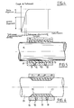
- the torque limiting blocking device shown in Fig. 1 comprises mounted on a tubular portion 1 of a steering column shaft a sleeve 2 made of solid metal, for example steel, provided in its outer surface with grooves 3 intended to receive the bolt 4 of a lock 5 for blocking the column in rotation.
- the sleeve 2 is mounted tight on the shaft 1 so as to create friction between the two parts.
- the friction torque is then proportional to the tightening which is a function of the tolerances of the parts.
- the manufacturing tolerances of the two parts must be very tight, which is not compatible with mass production of economical series.
- the dimensions of the internal bore of the sleeve 2 and of the external section of the shaft portion 1 intended to receive it are such that the tightening causes the deformation of the shaft portion 1 by the solid sleeve 2 up to a value exceeding its elastic limit, the residual tightening then remaining constant and dependent solely on the residual elasticity of the material constituting the shaft and on the length of the sleeve in contact with said shaft.
- the length of the sleeve 2 can be adjusted as a function of the characteristics of the material of the shaft 1.
- Fig.4 there is shown a curve representing the value of the friction torque as a function of the deformation obtained in the manner described above.
- the residual elasticity of the shaft 1 ensures friction by elastic clamping between the shaft 1 and the sleeve 2.
- the latter has, as shown in FIG. 2, an interior inlet cone -7 of slight slope, for example less than 15 °. , or a combination of cones and / or spokes so that the connection with the bore satisfies this condition.
- the establishment of the sleeve is carried out as follows. First of all, the sleeve 2 is fitted onto the shaft 1 of the column to a determined position, then it is moved back slightly, for example by 5 mm. This recoil no longer has contact between the inlet cone 7 of the sleeve, and the shaft 1 of the column.
- a locking device comprising a solid shaft portion and of constant section of a steering column on which is mounted a sleeve 9 provided with two end flanges reentrants 10 and thus delimiting with the outer surface of the shaft 8 an annular chamber 11-
- a plastic material is injected forming a friction lining 13.
- the elasticity of the sleeve 9 acts as a spring and the plastic material is used to obtain a constant coefficient of friction.
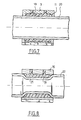
- Fig.6 there is shown a locking device similar to that of Fig.5 and in which the solid shaft portion 14 of the steering column has a portion 15 of reduced section on which is disposed a sleeve 1.6 without end flanges, the sleeve 16 and the outer surface of the reduced diameter portion 15 of the shaft 14 delimiting a chamber 17 into which a plastic friction material is injected through holes 18 made in the lateral surface of the sleeve 16 The injected plastic thus forms a friction lining 19.
- the elasticity of the sleeve 16 acts as a spring and the plastic of the lining serves to obtain a constant coefficient of friction.
- the device shown in Fig.7 is similar to that of Fig.5, except that the sleeve 9 is mounted on a portion of tubular shaft 20.
- the elasticity is then obtained by the deformation of the tube caused by injection into the annular chamber 11 of the plastic material constituting the packing 13.
- the device of Fig.8 is similar to that of Fig.6 with the exception that the sleeve 16 is mounted on a portion of reduced section 21, of a tubular shaft 22.
- the elasticity is obtained by the deformation of the tubular portion caused by the injection of the friction lining 19.
- the device represented in FIG. 9 is a variant of that of FIG. 7 in which on a tuhular shaft 20 of constant section there is a metal sleeve 23 open at one of its ends and provided at its opposite end with a re-entrant flange 24. Between the sleeve 23 and the shaft 20, a plastic insert 25 is placed, the role of which is similar to that of the linings 13 of the embodiments of FIGS. 5 and 7.
- the device of Fig.10 is a variant of the device of Fig.8 in which on the part 21 of reduced section of a tubular shaft 22 is disposed a sleeve 26, an insert insert 27 of plastic material being disposed in the cavity delimited by the outer surface of the narrowed part 21 of the shaft and the sleeve 26.
- the insert 27 can advantageously be constituted by a split tubular piece to facilitate its positioning on the narrowed portion 21 of the shaft.
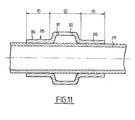
- the device shown in Fig.11 consists of a sleeve 28 mounted directly on a shaft 29 of constant section.
- the sleeve 28 has two bearing zones 30 by which the sleeve is engaged on the shaft 29 with a tightening causing the deformation of the shaft 29 exceeding its elastic limit and a central portion 31 of larger diameter in which are formed slots 32 regularly distributed around the periphery of the sleeve and intended to receive the bolt of the lock for blocking the rotation of the column (not shown).
- the portion is obtained by deformation shaft of the steering column or that of the sleeve mounted with clamping on a portion of the shaft, a friction torque between these two parts which, as shown in Fig.4 is determined by said deformation so as to be practically constant.
- a locking device for a steering column which, while calling upon a reduced number of parts, makes it possible to block the column and to allow rotation of the latter. above a torque exerted on the steering wheel which can be determined with precision.
Landscapes
- Engineering & Computer Science (AREA)
- Mechanical Engineering (AREA)
- General Engineering & Computer Science (AREA)
- Chemical & Material Sciences (AREA)
- Combustion & Propulsion (AREA)
- Transportation (AREA)
- Steering Controls (AREA)
- Mechanical Control Devices (AREA)
- Connection Of Plates (AREA)
Abstract
Dispositif de blocage de rotation à limitation de couple pour colonne de direction de véhicule automobile, comprenant monté sur la colonne de direction un manchon (2) dans la surface extérieure duquel sont ménagés des logements (3) destinés à recevoir le pêne (4) d'une serrure (5) de blocage de ladite colonne, caractérisé en ce que le manchon est monté sur la colonne avec un serrage provoquant la déformation de l'une au moins des deux pièces jusqu'au dépassement de la limite élastique du matériau dont elle est constituée.Torque limiting rotation blocking device for a motor vehicle steering column, comprising mounted on the steering column a sleeve (2) in the outer surface of which are formed housings (3) intended to receive the bolt (4) d a lock (5) for blocking said column, characterized in that the sleeve is mounted on the column with a tightening causing the deformation of at least one of the two parts until the elastic limit of the material of which it is exceeded consists.
Description
La présente invention est relative aux colonnes de direction pour véhicules automobiles et se rapporte plus particulièrement aux dispositifs de blocage à limitation de couple pour colonne de direction.The present invention relates to steering columns for motor vehicles and relates more particularly to torque limiting locking devices for steering column.
On connaît des dispositifs de blocage sans limitation de couple qui comportent une serrure de blocage en rotation de la colonne par immobilisation de celle-ci à l'aide d'un pêne coopérant avec une gâche solidaire de la colonne. Les dispositifs de ce type ont le défaut d'être détruits si le couple appliqué au volant porté par la colonne est suffisant pour provoquer la torsion ou la rupture du pêne de la serrure, ou encore le dégagement du pêne hors de la gâche.Locking devices are known without torque limitation which comprise a lock for blocking the rotation of the column by immobilizing the latter using a bolt cooperating with a keeper integral with the column. The devices of this type have the defect of being destroyed if the torque applied to the steering wheel carried by the column is sufficient to cause the twist or break of the bolt of the lock, or even the release of the bolt from the strike.
Avec les dispositifs sans limitation de couple, il est donc possible de libérer l'arbre de direction et, par conséquent, le volant du véhicule.With devices without torque limitation, it is therefore possible to release the steering shaft and, consequently, the steering wheel of the vehicle.
De plus, la destruction du dispositif de blocage provoque dans les pièces de celui-ci des déformations qui risquent de causer un blocage intempestif de la colonne de direction.In addition, the destruction of the locking device causes in the parts of it deformations which may cause inadvertent blocking of the steering column.
Afin de remédier à ces inconvénients on a proposé des dispositifs de blocage à limitation de couple qui autorisent la rotation de l'arbre sans destruction des pièces, à partir d'un certain couple de rotation appliqué au volant, ce couple étant toutefois suffisamment élevé pour interdire la conduite du véhicule.In order to remedy these drawbacks, torque limiting locking devices have been proposed which allow the rotation of the shaft without destroying the parts, from a certain torque applied to the flywheel, this torque however being sufficiently high for prohibit driving the vehicle.
Parmi les dispositifs de blocage de ce second type,on connaît les dispositifs à friction comportant un manchon pourvu d'une fente pour l'introduction d'un pêne de blocage. Le manchon est monté sur l'arbre de la colonne de direction par l'intermédiaire d'une troisième pièce telle qu'un ressort, des rondelles élastiques,etc..qui détermine la valeur de l'effort de friction à vaincre pour pouvoir tourner l'arbre par rapport au manchon.Among the locking devices of this second type, friction devices are known comprising a sleeve provided with a slot for the introduction of a locking bolt. The sleeve is mounted on the steering column shaft by means of a third part such as a spring, elastic washers, etc. which determines the value of the friction force to be overcome in order to be able to turn. the shaft relative to the sleeve.
On connaît également les dispositifs de blocage à désaccouplement de secteurs dentés.Known blocking devices for toothed sectors are also known.
Un tel dispositif comporte une douille liée à l'arbre de la colonne de direction et comportant à l'une de ses extrémités des dents radiales qui coopèrent avec des dents radiales correspondantes prévues sur un manchon fixe en rotation entourant l'arbre. Un ressort assure le maintien en contact des dentures de la douille et du manchon. Lorsque le couple appliqué à l'arbre atteint une valeur prédéterminée, les efforts sur les dentures ont une composante axiale qui provoque le déplacement axial du manchon et le désaccouplement de la colonne avec celui-ci pendant l'application de ce couple.Such a device comprises a socket linked to the shaft of the steering column and comprising at one of its ends radial teeth which cooperate with corresponding radial teeth provided on a fixed sleeve in rotation surrounding the shaft. A spring keeps the teeth of the sleeve and the sleeve in contact. When the torque applied to the shaft reaches a predetermined value, the forces on the teeth have an axial component which causes the axial displacement of the sleeve and the uncoupling of the column with the latter during the application of this torque.
L'invention vise à perfectionner les dispositifs de blocage à limitation de couple en créant un tel dispositif dont la construction nécessite un nombre de pièces inférieur au nombre de pièces entrant dans la construction des dispositifs connus.The invention aims to improve the torque limiting blocking devices by creating such a device whose construction requires a number of parts less than the number of parts used in the construction of known devices.
Elle a donc pour objet un dispositif de blocage en rotation à limitation de couple pour colonne de direction de véhicule automobile, comprenant monté sur la colonne de direction, un manchon dans la surface extérieure duquel sont ménagés des logements destinés à recevoir le pêne d'une serrure de blocage de ladite colonne, caractérisé en ce que le manchon est monté sur la colonne avec un serrage provoquant la déformation de l'une au moins des deux pièces jusqu'au dépassement de la limite élastique du matériau dont elle est constituée.It therefore relates to a torque limiting rotation blocking device for a motor vehicle steering column, comprising mounted on the steering column, a sleeve in the outer surface of which are housed for receiving the bolt of a lock for locking said column, characterized in that the sleeve is mounted on the column with a tightening causing the deformation of at least one of the two parts until the elastic limit of the material of which it is made is exceeded.
L'invention sera mieux comprise à la lecture de la description qui va suivre, faite en référence aux dessins annexés, donnés uniquement à titre d'exemples et sur lesquels :
- - la Fig.1 est une vue schématique en coupe d'un dispositif de blocage à limitation de couple suivant l'invention;
- - la Fig.2 est une vue en élévation et en coupe du manchon entrant dans la construction du dispositif de blocage suivant l'invention ;
- - la Fig.3 est une vue en bout du manchon de la Fig.2 ;
- - la Fig.4 est un graphique montrant la courbe du couple de frottement en fonction de la déformation ;
- - la Fig.5 est une vue en coupe d'un manchon pourvu d'un insert en matériau de friction, monté sur une portion d'arbre plein de section constante ;
- - la Fig.6 est une vue en coupe d'un manchon pourvu d'une garniture intérieure en matériau de friction monté sur une portion de section réduite d'un arbre plein de colonne de direction ;
- - les Fig. 7 et 8 sont des vues en coupe de variantes respectives des agencements des Fig.5 et 6 appliquées à des arbres tubulaires ;
- - les Fig.9 et 10 sont des vues en coupe de variantes respectives des agencements des Fig.7 et 8 à inserts rapportés ;
- - la Fig.11 est une vue en coupe d'un dispositif suivant l'invention pourvu d'un manchon à deux portées de friction.
- - Fig.1 is a schematic sectional view of a torque limiting locking device according to the invention;
- - Fig.2 is an elevational and sectional view of the sleeve used in the construction of the locking device according to the invention;
- - Fig.3 is an end view of the sleeve of Fig.2;
- - Fig.4 is a graph showing the curve of the friction torque as a function of the deformation;
- - Fig.5 is a sectional view of a sleeve provided with an insert of friction material, mounted on a solid shaft portion of constant section;
- - Fig.6 is a sectional view of a sleeve provided with an inner lining of friction material mounted on a portion of reduced section of a solid shaft of the steering column;
- - Figs. 7 and 8 are sectional views of respective variants of the arrangements of F IG.5 and 6 applied to tubular shafts;
- - Fig.9 and 10 are sectional views of respective variants of the arrangements of Fig.7 and 8 with reported inserts;
- - Fig.11 is a sectional view of a device according to the invention provided with a sleeve with two friction surfaces.
Le dispositif de blocage à limitation de couple représenté à la Fig.1 comporte monté sur une portion tubulaire 1 d'un arbre de colonne de direction un manchon 2 en métal massif, de l'acier par exemple, pourvu dans sa surface extérieure de rainures 3 destinées à recevoir le pêne 4 d'une serrure 5 de blocage de la colonne en rotation.The torque limiting blocking device shown in Fig. 1 comprises mounted on a
Le manchon 2 est monté serré sur l'arbre 1 de manière à créer un frottement entre les deux pièces. Le couple de frottement est alors proportionnel au serrage qui est fonction des tolérances des pièces. Mais, lorsque le couple de frottement désiré doit être compris dans un intervalle de valeurs très proches, les tolérances de fabrication des deux pièces doivent être très serrées, ce qui n'est pas compatible avec une fabrication de grande série économique.The
Afin que le couple de frottement obtenu ne soit pas fonction des tolérances des pièces, suivant l'invention, les cotes de l'alésage interne du manchon 2 et de la section extérieure de la portion d'arbre 1 destiné à le recevoir, sont telles que le serrage provoque la déformation de la portion d'arbre 1 par le manchon massif 2 jusqu'à une valeur dépassant sa limite élastique, le serrage résiduel restant alors constant et dépendant uniquement de l'élasticité résiduelle du matériau constituant l'arbre et de la longueur du manchon en contact avec ledit arbre.So that the friction torque obtained does not depend on the tolerances of the parts, according to the invention, the dimensions of the internal bore of the
Pour obtenir la dispersion minimale sur le couple de frottement,la longueur du manchon 2 peut être modulée en fonction des caractéristiques du matériau de l'arbre 1.To obtain the minimum dispersion over the friction torque, the length of the
Bien entendu, on peut également choisir la solution complémentaire qui consiste à provoquer la déformation plastique du manchon 2, alors que la cote de la portion d'arbre sur laquelle il est monté reste constante.Of course, one can also choose the complementary solution which consists in causing the plastic deformation of the
Sur la Fig.4, on a représenté une courbe représentant la valeur du couple de frottement en fonction de la déformation obtenue de la manière décrite ci-dessus. Dans l'agencement représenté à la Fig.1, l'élasticité résiduelle de l'arbre 1 permet d'assurer un frottement par serrage élastique entre l'arbre 1 et le manchon 2.In Fig.4, there is shown a curve representing the value of the friction torque as a function of the deformation obtained in the manner described above. In the arrangement shown in Fig.1, the residual elasticity of the
Lorsque l'arbre 1 de la colonne est réalisé plein, on provoque la déformation du manchon monté sur celui-ci.When the
Pour permettre de réaliser un montage à emmanchement serré, avec un serrage au-delà de la limite élastique de l'une des pièces, il est nécessaire que le diamètre extérieur de l'arbre 1, avant emmanchement, soit supérieur au diamètre intérieur de l'alésage 6 du manchon 2 d'une valeur au-delà des tolérances serrées normales.To allow a tight fitting assembly, with a tightening beyond the elastic limit of one of the parts, it is necessary that the outside diameter of the
Pour faciliter l'introduction du manchon 2 et surtout pour conserver un maximum d'élasticité résiduelle, celui-ci présente, comme représenté à la Fig.2, un cône d'entrée intérieur -7 de faible pente, par exemple inférieur à 15°, ou une combinaison de cônes et/ou de rayons de telle sorte que le raccordement avec l'alésage satisfasse cette condition.To facilitate the introduction of the
Afin que le cône d'entrée 7 du manchon 2 ne perturbe pas le fonctionnement du système et ne participe pas au couple de frottement, la mise en place du manchon est réalisée de la manière suivante. Tout d'abord, on emmanche le manchon 2 sur l'arbre 1 de la colonne jusqu'à une position déterminée, puis on le recule légèrement, par exemple de 5 mm. Ce recul permet de ne plus avoir de contact entre le cône d'entrée 7 du manchon, et l'arbre 1 de la colonne.So that the
Sur la Fig.5, on a représenté en coupe un dispositif de blocage suivant l'invention comprenant une portion d'arbre plein et de section constante d'une colonne de direction sur laquelle est monté un manchon 9 pourvu de deux rebords d'extrémité rentrants 10 et délimitant ainsi avec la surface extérieure de l'arbre 8 une chambre annulaire 11- Dans la surface latérale du manchon 9 sont ménagés des trous 12 par lesquels est injectée une matière plastique formant une garniture de friction 13. L'élasticité du manchon 9 fait office de ressort et la matière plastique sert à obtenir un coefficient de frottement constant.In Fig.5, there is shown in section a locking device according to the invention comprising a solid shaft portion and of constant section of a steering column on which is mounted a
Sur la Fig.6 on a représenté un dispositif de blocage analogue à celui de la Fig.5 et dans lequel la portion d'arbre plein 14 de la colonne de direction comporte une portion 15 de section réduite sur laquelle est disposé un manchon 1.6 dépourvu de rebords d'extrémité, le manchon 16 et la surface extérieure de la partie de diamètre réduit 15 de l'arbre 14 délimitant une chambre 17 dans laquelle une matière plastique de friction est injectée par des trous 18 ménagés dans la surface latérale du manchon 16. La matière plastique injectée forme ainsi une garniture de friction 19. Ici encore l'élasticité du manchon 16 fait office de ressort et la matière plastique de la garniture sert à obtenir un coefficient de frottement constant.In Fig.6 there is shown a locking device similar to that of Fig.5 and in which the
Le dispositif représenté à la Fig.7 est analogue à celui de la Fig.5, à l'exception du fait que le manchon 9 est monté sur une portion d'arbre 20 tubulaire. L'élasticité est alors obtenue par la déformation du tube provoquée par l'injection dans la chambre annulaire 11 de la matière plastique constituant la garniture 13.The device shown in Fig.7 is similar to that of Fig.5, except that the
Le dispositif de la Fig.8 est analogue à celui de la Fig.6 à l'exception du fait que le manchon 16 est monté sur une portion de section réduite 21, d'un arbre tubulaire 22. Ici encore, l'élasticité est obtenue par la déformation de la portion tubulaire provoquée par l'injection de la garniture de friction 19.The device of Fig.8 is similar to that of Fig.6 with the exception that the
Le dispositif représenté à la Fig.9 est une variante de celui de la Fig.7 dans laquelle sur un arbre tuhulaire 20 de section constante on dispose un manchon métallique 23 ouvert à l'une de ses extrémités et pourvu à son extrémité opposée d'un rebord rentrant 24. Entre le manchon 23 et l'arbre 20, on met en place un insert en matière plastique 25 dont le rôle est analogue à celui des garnitures 13 des modes de réalisation des Fig.5 et 7.The device represented in FIG. 9 is a variant of that of FIG. 7 in which on a
Le dispositif de la Fig.10 est une variante du dispositif de la Fig.8 dans laquelle sur la partie 21 de section réduite d'un arbre tubulaire 22 est disposé un manchon 26, un insert rapporté 27 en matière plastique étant disposé dans la cavité délimitée par la surface extérieure de la partie rétrécie 21 de l'arbre et le manchon 26.The device of Fig.10 is a variant of the device of Fig.8 in which on the
L'insert 27 peut avantageusement être constitué par une pièce tubulaire fendue pour faciliter sa mise en place sur la portion rétrécie 21 de l'arbre.The
Le dispositif représenté à la Fig.11 est constitué d'un manchon 28 monté directement sur un arbre 29 de section constante. Le manchon 28 comporte deux zones de portée 30 par lesquelles le manchon est engagé sur l'arbre 29 avec un serrage provoquant la déformation de l'arbre 29 dépassant sa limite élastique et une portion centrale 31 de plus grand diamètre dans laquelle sont ménagées des fentes 32 régulièrement réparties à la périphérie du manchon et destinées à recevoir le pêne de la serrure de blocage en rotation de la colonne (non représenté).The device shown in Fig.11 consists of a
On voit donc que dans tous les modes fc réalisation décrits ci-dessus, on obtient par déformation de la portion d'arbre de la colonne de direction ou par celle du manchon monté avec serrage sur une portion d'arbre, un couple de frottement entre ces deux pièces qui, comme le montre la Fig.4 est déterminé par ladite déformation de manière à être pratiquement constant. On obtient donc, grâce à l'invention, un dispositif de blocage pour colonne de direction qui, tout en faisant appel à un nombre de pièces réduit au minimum permet d'assurer le blocage de la colonne et d'autoriser la rotation de celle-ci au-delà d'un couple exercé sur le volant qui peut être déterminé avec précision.It can therefore be seen that in all the embodiments described above, the portion is obtained by deformation shaft of the steering column or that of the sleeve mounted with clamping on a portion of the shaft, a friction torque between these two parts which, as shown in Fig.4 is determined by said deformation so as to be practically constant. We therefore obtain, thanks to the invention, a locking device for a steering column which, while calling upon a reduced number of parts, makes it possible to block the column and to allow rotation of the latter. above a torque exerted on the steering wheel which can be determined with precision.
Claims (9)
Applications Claiming Priority (2)
| Application Number | Priority Date | Filing Date | Title |
|---|---|---|---|
| FR8508262 | 1985-05-31 | ||
| FR8508262A FR2582751B1 (en) | 1985-05-31 | 1985-05-31 | TORQUE LIMITING ROTATION LOCKING DEVICE FOR A STEERING COLUMN OF A MOTOR VEHICLE |
Publications (2)
| Publication Number | Publication Date |
|---|---|
| EP0204621A1 true EP0204621A1 (en) | 1986-12-10 |
| EP0204621B1 EP0204621B1 (en) | 1989-03-15 |
Family
ID=9319763
Family Applications (1)
| Application Number | Title | Priority Date | Filing Date |
|---|---|---|---|
| EP86401145A Expired EP0204621B1 (en) | 1985-05-31 | 1986-05-29 | Torque-limiting device for an automotive vehicle's steering column |
Country Status (7)
| Country | Link |
|---|---|
| US (1) | US4854141A (en) |
| EP (1) | EP0204621B1 (en) |
| JP (1) | JPH06104454B2 (en) |
| AU (1) | AU582445B2 (en) |
| DE (1) | DE3662443D1 (en) |
| ES (1) | ES8706910A1 (en) |
| FR (1) | FR2582751B1 (en) |
Cited By (6)
| Publication number | Priority date | Publication date | Assignee | Title |
|---|---|---|---|---|
| FR2642462A1 (en) * | 1989-02-01 | 1990-08-03 | Nacam | LOCK FOR LOCKING LOCK IN ROTATION OF A SHAFT AND ITS APPLICATION TO AUTOMOTIVE STEERING BOLTS |
| FR2719273A1 (en) * | 1994-04-29 | 1995-11-03 | Renault | Torque limitation lock for steering column. |
| FR2724469A1 (en) * | 1994-09-14 | 1996-03-15 | Ecia Equip Composants Ind Auto | Torque-limited rotary lock for steering column of motor vehicle |
| WO1997048915A1 (en) * | 1996-06-19 | 1997-12-24 | Baumann & Cie Ag | Drive system |
| FR2810947A1 (en) | 2000-06-29 | 2002-01-04 | Ecia Equip Composants Ind Auto | Car steering column is fitted with locking sleeve which can be fixed against it by bolt fitting into aperture in its outer surface, column having longitudinal ridges and troughs which compensate for tolerances in column and sleeve |
| CN101290085B (en) * | 2007-04-20 | 2013-08-21 | Gkn动力传动系统国际有限责任公司 | Method for producing hollow section, hollow section and transmission system for vehicle |
Families Citing this family (21)
| Publication number | Priority date | Publication date | Assignee | Title |
|---|---|---|---|---|
| US5205790A (en) * | 1989-05-22 | 1993-04-27 | Ecia | Steering-wheel shaft forming an anti-theft lock element |
| GB2281888B (en) * | 1993-09-21 | 1997-01-22 | Valeo Security Systems Ltd | Steering column lock |
| GB2298448A (en) * | 1995-03-02 | 1996-09-04 | Torrington Co | Steering column locking assembly |
| JP3453909B2 (en) * | 1995-03-17 | 2003-10-06 | 日本精工株式会社 | Steering lock device |
| US6094951A (en) * | 1997-02-27 | 2000-08-01 | The Torrington Company | Steering column locking and torque limiting bearing support sleeve |
| US5887463A (en) * | 1997-06-24 | 1999-03-30 | The Torrington Company | Steering column locking pin |
| DE10031902B4 (en) * | 2000-06-30 | 2005-06-16 | Daimlerchrysler Ag | Overload protection and a method for their production |
| DE10053753C1 (en) * | 2000-10-30 | 2002-04-18 | Audi Ag | Device for locking motor vehicle's steering shaft has locking component located inside column tube close to steering wheel end of steering shaft, and motor near to end of shaft on foot well side |
| JP2003072517A (en) * | 2001-09-05 | 2003-03-12 | Koyo Seiko Co Ltd | Steering lock device |
| WO2004091995A2 (en) * | 2003-04-08 | 2004-10-28 | Timken U.S. Coporation | Zero clearance controlled friction bearing |
| FR2861673B1 (en) * | 2003-11-05 | 2007-06-29 | Nacam | ROTATION BLOCKING DEVICE WITH TORQUE LIMITATION OF A STEERING COLUMN OF A MOTOR VEHICLE |
| DE502005008574D1 (en) | 2004-02-26 | 2010-01-07 | Thyssenkrupp Presta Ag | Locking sleeve for a steering column and method of making the same |
| EP1728696B1 (en) * | 2005-06-01 | 2011-08-10 | Nsk Ltd. | Steering device |
| JP5122269B2 (en) * | 2007-12-27 | 2013-01-16 | ヒルタ工業株式会社 | Slip torque setting mechanism of the key lock attached to the steering shaft |
| US7562548B1 (en) * | 2008-06-16 | 2009-07-21 | Delphi Technologies, Inc. | Steering column assembly |
| JP5326917B2 (en) * | 2008-09-30 | 2013-10-30 | 株式会社ジェイテクト | Steering device |
| JP5218083B2 (en) * | 2009-01-19 | 2013-06-26 | 日本精工株式会社 | Steering device |
| WO2014080845A1 (en) * | 2012-11-26 | 2014-05-30 | 日本精工株式会社 | Steering device |
| CN103661561B (en) * | 2013-12-31 | 2016-06-01 | 长城汽车股份有限公司 | Car steering tube column |
| JP6166427B1 (en) * | 2016-06-02 | 2017-07-19 | 株式会社東海理化電機製作所 | Steering lock device |
| JP7126877B2 (en) * | 2018-06-22 | 2022-08-29 | 株式会社山田製作所 | steering device |
Citations (9)
| Publication number | Priority date | Publication date | Assignee | Title |
|---|---|---|---|---|
| GB294034A (en) * | 1927-10-28 | 1928-07-19 | Clifford Covering Company Ltd | Improvements in and relating to the hubs of hand wheels |
| FR1020290A (en) * | 1950-06-16 | 1953-02-04 | How to assemble an exterior part on an interior part | |
| CH368345A (en) * | 1959-09-17 | 1963-03-31 | Melle Usines Sa | Assembly process of mechanical parts |
| GB996932A (en) * | 1962-12-20 | 1965-06-30 | Peugeot & Cie | Rotary motion coupling device |
| FR1419285A (en) * | 1964-01-03 | 1965-11-26 | Kodak Pathe | Method of manufacturing a friction coupling |
| US3230739A (en) * | 1963-05-23 | 1966-01-25 | Clevite Harris Products Inc | Slip clutch |
| FR2057347A5 (en) * | 1969-08-13 | 1971-05-21 | Metivier Christian | Shock absorbing joints between moving parts |
| FR2319796A1 (en) * | 1975-07-30 | 1977-02-25 | Roulements Soc Nouvelle | METHOD AND DEVICE FOR ASSEMBLING ELEMENTS |
| US4041730A (en) * | 1976-02-11 | 1977-08-16 | Dana Corporation | Marine propeller bushing coupling |
Family Cites Families (22)
| Publication number | Priority date | Publication date | Assignee | Title |
|---|---|---|---|---|
| US1146345A (en) * | 1914-05-11 | 1915-07-13 | Karl Oppermann | Steering-post lock. |
| US3023995A (en) * | 1958-07-21 | 1962-03-06 | William C N Hopkins | Sealing and coupling structures |
| FR85727E (en) * | 1961-01-19 | 1965-10-01 | Wilmot Breeden Ltd | Anti-theft for motor vehicles |
| US3187527A (en) * | 1961-08-21 | 1965-06-08 | Wilmot Breeden Ltd | Theft prevention devices |
| FR1427941A (en) * | 1964-12-30 | 1966-02-11 | Simca Automobiles Sa | Steering lock lock fixing device, in particular for motor vehicles |
| US3570286A (en) * | 1968-08-30 | 1971-03-16 | Kenneth L Rohrbough | Theft reducer lock means |
| US3566633A (en) * | 1968-11-07 | 1971-03-02 | Borg Warner | Steering column lock |
| FR2133190A5 (en) * | 1971-04-13 | 1972-11-24 | Neiman Exploitation Brevets | |
| JPS4734819U (en) * | 1971-05-11 | 1972-12-18 | ||
| JPS48104228A (en) * | 1972-04-11 | 1973-12-27 | ||
| DE2904386A1 (en) * | 1979-02-06 | 1980-08-07 | Daimler Benz Ag | Antitheft steering lock for vehicle - has shear pin to inhibit ignition and steering if forced |
| AU545715B2 (en) * | 1980-02-19 | 1985-07-25 | Industrial Pipe Systems Pty Limited | Method for joining plastic pipes |
| FR2477488A1 (en) * | 1980-03-04 | 1981-09-11 | Peugeot | DEVICE FOR LOCKING A STEERING COLUMN OF A MOTOR VEHICLE |
| JPS57191149A (en) * | 1981-05-18 | 1982-11-24 | Nissan Motor Co Ltd | Lock mechanism for steering shaft |
| AT372314B (en) * | 1981-07-03 | 1983-09-26 | Supervis Ets | STEERING SPINDLE FOR STEERING DEVICES IN MOTOR VEHICLES |
| DE3216168C2 (en) * | 1982-04-30 | 1984-05-17 | Neiman GmbH, 5657 Haan | Device for locking the rotational movement of a steering shaft of a motor vehicle |
| JPS5973349A (en) * | 1982-10-20 | 1984-04-25 | Kokusan Kinzoku Kogyo Co Ltd | Device for preventing steering lock from breakage |
| US4559795A (en) * | 1983-06-09 | 1985-12-24 | Zagoroff Dimiter S | Passive anti-theft device for vehicle ignition lock |
| SE450236B (en) * | 1983-06-13 | 1987-06-15 | Kalevi Honkanen | DEVICE AT RATTLAS |
| DE3435084A1 (en) * | 1984-09-25 | 1986-04-03 | Daimler-Benz Ag, 7000 Stuttgart | Steering lock for motor vehicles |
| FR2586636B1 (en) * | 1985-09-03 | 1987-12-04 | Peugeot Cycles | ANTI-THEFT DEVICE FOR A STEERING COLUMN OF A MOTOR VEHICLE |
| GB2187422B (en) * | 1986-03-04 | 1989-04-19 | Torrington Co | Vehicle steering column |
-
1985
- 1985-05-31 FR FR8508262A patent/FR2582751B1/en not_active Expired
-
1986
- 1986-05-29 DE DE8686401145T patent/DE3662443D1/en not_active Expired
- 1986-05-29 AU AU58048/86A patent/AU582445B2/en not_active Ceased
- 1986-05-29 EP EP86401145A patent/EP0204621B1/en not_active Expired
- 1986-05-30 JP JP61125573A patent/JPH06104454B2/en not_active Expired - Lifetime
- 1986-05-30 ES ES556108A patent/ES8706910A1/en not_active Expired
-
1987
- 1987-12-04 US US07/129,955 patent/US4854141A/en not_active Expired - Fee Related
Patent Citations (9)
| Publication number | Priority date | Publication date | Assignee | Title |
|---|---|---|---|---|
| GB294034A (en) * | 1927-10-28 | 1928-07-19 | Clifford Covering Company Ltd | Improvements in and relating to the hubs of hand wheels |
| FR1020290A (en) * | 1950-06-16 | 1953-02-04 | How to assemble an exterior part on an interior part | |
| CH368345A (en) * | 1959-09-17 | 1963-03-31 | Melle Usines Sa | Assembly process of mechanical parts |
| GB996932A (en) * | 1962-12-20 | 1965-06-30 | Peugeot & Cie | Rotary motion coupling device |
| US3230739A (en) * | 1963-05-23 | 1966-01-25 | Clevite Harris Products Inc | Slip clutch |
| FR1419285A (en) * | 1964-01-03 | 1965-11-26 | Kodak Pathe | Method of manufacturing a friction coupling |
| FR2057347A5 (en) * | 1969-08-13 | 1971-05-21 | Metivier Christian | Shock absorbing joints between moving parts |
| FR2319796A1 (en) * | 1975-07-30 | 1977-02-25 | Roulements Soc Nouvelle | METHOD AND DEVICE FOR ASSEMBLING ELEMENTS |
| US4041730A (en) * | 1976-02-11 | 1977-08-16 | Dana Corporation | Marine propeller bushing coupling |
Cited By (9)
| Publication number | Priority date | Publication date | Assignee | Title |
|---|---|---|---|---|
| FR2642462A1 (en) * | 1989-02-01 | 1990-08-03 | Nacam | LOCK FOR LOCKING LOCK IN ROTATION OF A SHAFT AND ITS APPLICATION TO AUTOMOTIVE STEERING BOLTS |
| EP0381554A1 (en) * | 1989-02-01 | 1990-08-08 | Nacam | Striking bush for a rotation blocking lock of a shaft and its application for steering column locks of automobiles |
| US5092145A (en) * | 1989-02-01 | 1992-03-03 | Nacam | Keeper for a lock for the rotational blocking of a shaft and its use on motor vehicle steering column anti-theft devices |
| FR2719273A1 (en) * | 1994-04-29 | 1995-11-03 | Renault | Torque limitation lock for steering column. |
| EP0683075A1 (en) * | 1994-04-29 | 1995-11-22 | Regie Nationale Des Usines Renault S.A. | Torque-limiting anti-theft device for a steering column |
| FR2724469A1 (en) * | 1994-09-14 | 1996-03-15 | Ecia Equip Composants Ind Auto | Torque-limited rotary lock for steering column of motor vehicle |
| WO1997048915A1 (en) * | 1996-06-19 | 1997-12-24 | Baumann & Cie Ag | Drive system |
| FR2810947A1 (en) | 2000-06-29 | 2002-01-04 | Ecia Equip Composants Ind Auto | Car steering column is fitted with locking sleeve which can be fixed against it by bolt fitting into aperture in its outer surface, column having longitudinal ridges and troughs which compensate for tolerances in column and sleeve |
| CN101290085B (en) * | 2007-04-20 | 2013-08-21 | Gkn动力传动系统国际有限责任公司 | Method for producing hollow section, hollow section and transmission system for vehicle |
Also Published As
| Publication number | Publication date |
|---|---|
| FR2582751B1 (en) | 1988-05-06 |
| JPH06104454B2 (en) | 1994-12-21 |
| JPS61278466A (en) | 1986-12-09 |
| ES556108A0 (en) | 1987-07-01 |
| DE3662443D1 (en) | 1989-04-20 |
| US4854141A (en) | 1989-08-08 |
| ES8706910A1 (en) | 1987-07-01 |
| FR2582751A1 (en) | 1986-12-05 |
| AU582445B2 (en) | 1989-03-23 |
| EP0204621B1 (en) | 1989-03-15 |
| AU5804886A (en) | 1986-12-04 |
Similar Documents
| Publication | Publication Date | Title |
|---|---|---|
| EP0204621B1 (en) | Torque-limiting device for an automotive vehicle's steering column | |
| EP0148794B1 (en) | Angular-position adjuster of a rotary driving part coupled to a rotary driven part | |
| WO1996014526A1 (en) | Lock-up clutch for a hydrokinetic coupling device, in particular for motor vehicles, and method for mounting same | |
| FR2771370A1 (en) | BICYCLE WHEEL HUB SUPPORT DEVICE | |
| FR2947592A1 (en) | DEVICE FOR THE MECHANICAL BONDING OF AT LEAST TWO COAXIALLY BORED PIECES | |
| FR3039863A1 (en) | PULLEY DEVICE FOR TILT ROLLER OR ROLLER | |
| EP0551047B1 (en) | Holding device with removable guide bush | |
| EP1136342B1 (en) | Pressing yoke arrangement for a motor vehicle rack-and-pinion steering | |
| FR2723989A1 (en) | SYSTEM FOR IMMOBILIZING AN EXTENDED ORGAN | |
| FR2544816A1 (en) | Torque transmission device, of the sliding type, especially for motor vehicle steering | |
| FR2734616A1 (en) | MULTIPLE DISC FRICTION CLUTCH HAVING AN AXIAL STOP | |
| WO1991005694A1 (en) | Adjusting and locking device for mounting a cycle wheel hub | |
| FR2757228A1 (en) | DEVICE FOR PERMANENT COUPLING OF TWO TREES | |
| FR2919361A1 (en) | Nut locking pin for assembling car wheel hub, has deformable element connected to cylindrical element, such that deformable element is retracted to surround ring to prevent cylindrical element disengaged from position of cylindrical element | |
| FR2658878A1 (en) | Quick connection device between two portions of a linkage, particularly for a motor vehicle | |
| FR2799515A1 (en) | GAME RETRIEVAL SYSTEM FOR ATTACHING TWO PIECES TO EACH OTHER USING A SCREW TYPE FASTENER | |
| FR2516185A1 (en) | NUT BRAKING DEVICE | |
| WO2002057645A1 (en) | Mounting a radial web on a hub, in particular for a motor vehicle clutch disc | |
| FR2723156A1 (en) | DEVICE FOR CONNECTING A SHAFT, IN PARTICULAR FOR STEERING A MOTOR VEHICLE AND A CARDAN FORK | |
| WO1999008037A1 (en) | Device for quick connection of a tube to a rigid element | |
| FR2921704A1 (en) | Wheel hub and spindle assembly, has locking unit with central opening whose shape is adopted to cooperate with exterior shape of nut, where locking unit is force-mounted at interior of cylindrical cavity | |
| FR2764256A1 (en) | MOTOR VEHICLE ANTITHEFT COMPRISING IMPROVED IMMOBILIZATION MEANS | |
| EP1884673B1 (en) | Coupling system and braking system | |
| FR2668240A1 (en) | DEVICE FOR CONNECTING TWO PIPES ON BOTH PARTS AND OTHER OF A PARTITION ELEMENT. | |
| FR2805869A1 (en) | Anti-vibration bush for a crank arm where the rubber bush is force fitted into the outer sleeve |
Legal Events
| Date | Code | Title | Description |
|---|---|---|---|
| PUAI | Public reference made under article 153(3) epc to a published international application that has entered the european phase |
Free format text: ORIGINAL CODE: 0009012 |
|
| 17P | Request for examination filed |
Effective date: 19861018 |
|
| AK | Designated contracting states |
Kind code of ref document: A1 Designated state(s): DE GB IT NL SE |
|
| 17Q | First examination report despatched |
Effective date: 19880202 |
|
| ITF | It: translation for a ep patent filed | ||
| GRAA | (expected) grant |
Free format text: ORIGINAL CODE: 0009210 |
|
| AK | Designated contracting states |
Kind code of ref document: B1 Designated state(s): DE GB IT NL SE |
|
| GBT | Gb: translation of ep patent filed (gb section 77(6)(a)/1977) | ||
| REF | Corresponds to: |
Ref document number: 3662443 Country of ref document: DE Date of ref document: 19890420 |
|
| PLBI | Opposition filed |
Free format text: ORIGINAL CODE: 0009260 |
|
| 26 | Opposition filed |
Opponent name: MERCEDES- BENZ AG Effective date: 19891214 |
|
| NLR1 | Nl: opposition has been filed with the epo |
Opponent name: MERCEDES-BENZ AG. |
|
| ITTA | It: last paid annual fee | ||
| PLBM | Termination of opposition procedure: date of legal effect published |
Free format text: ORIGINAL CODE: 0009276 |
|
| STAA | Information on the status of an ep patent application or granted ep patent |
Free format text: STATUS: OPPOSITION PROCEDURE CLOSED |
|
| 27C | Opposition proceedings terminated |
Effective date: 19910928 |
|
| PGFP | Annual fee paid to national office [announced via postgrant information from national office to epo] |
Ref country code: SE Payment date: 19940517 Year of fee payment: 9 |
|
| PGFP | Annual fee paid to national office [announced via postgrant information from national office to epo] |
Ref country code: NL Payment date: 19940531 Year of fee payment: 9 |
|
| EAL | Se: european patent in force in sweden |
Ref document number: 86401145.7 |
|
| PG25 | Lapsed in a contracting state [announced via postgrant information from national office to epo] |
Ref country code: SE Effective date: 19950530 |
|
| PG25 | Lapsed in a contracting state [announced via postgrant information from national office to epo] |
Ref country code: NL Effective date: 19951201 |
|
| NLV4 | Nl: lapsed or anulled due to non-payment of the annual fee |
Effective date: 19951201 |
|
| EUG | Se: european patent has lapsed |
Ref document number: 86401145.7 |
|
| PGFP | Annual fee paid to national office [announced via postgrant information from national office to epo] |
Ref country code: GB Payment date: 20000524 Year of fee payment: 15 |
|
| PGFP | Annual fee paid to national office [announced via postgrant information from national office to epo] |
Ref country code: DE Payment date: 20000706 Year of fee payment: 15 |
|
| PG25 | Lapsed in a contracting state [announced via postgrant information from national office to epo] |
Ref country code: GB Free format text: LAPSE BECAUSE OF NON-PAYMENT OF DUE FEES Effective date: 20010529 |
|
| GBPC | Gb: european patent ceased through non-payment of renewal fee |
Effective date: 20010529 |
|
| PG25 | Lapsed in a contracting state [announced via postgrant information from national office to epo] |
Ref country code: DE Free format text: LAPSE BECAUSE OF NON-PAYMENT OF DUE FEES Effective date: 20020301 |
|
| PG25 | Lapsed in a contracting state [announced via postgrant information from national office to epo] |
Ref country code: IT Free format text: LAPSE BECAUSE OF NON-PAYMENT OF DUE FEES;WARNING: LAPSES OF ITALIAN PATENTS WITH EFFECTIVE DATE BEFORE 2007 MAY HAVE OCCURRED AT ANY TIME BEFORE 2007. THE CORRECT EFFECTIVE DATE MAY BE DIFFERENT FROM THE ONE RECORDED. Effective date: 20050529 |