EP0204043A2 - Procédé de fabrication d'une pièce métallique présentant une bride annulaire - Google Patents
Procédé de fabrication d'une pièce métallique présentant une bride annulaire Download PDFInfo
- Publication number
- EP0204043A2 EP0204043A2 EP85303985A EP85303985A EP0204043A2 EP 0204043 A2 EP0204043 A2 EP 0204043A2 EP 85303985 A EP85303985 A EP 85303985A EP 85303985 A EP85303985 A EP 85303985A EP 0204043 A2 EP0204043 A2 EP 0204043A2
- Authority
- EP
- European Patent Office
- Prior art keywords
- billet
- lower die
- cavity
- die elements
- providing
- Prior art date
- Legal status (The legal status is an assumption and is not a legal conclusion. Google has not performed a legal analysis and makes no representation as to the accuracy of the status listed.)
- Granted
Links
- 239000002184 metal Substances 0.000 title claims abstract description 45
- 229910052751 metal Inorganic materials 0.000 title claims abstract description 45
- 238000000034 method Methods 0.000 title claims abstract description 23
- NJPPVKZQTLUDBO-UHFFFAOYSA-N novaluron Chemical compound C1=C(Cl)C(OC(F)(F)C(OC(F)(F)F)F)=CC=C1NC(=O)NC(=O)C1=C(F)C=CC=C1F NJPPVKZQTLUDBO-UHFFFAOYSA-N 0.000 claims description 11
- 238000001125 extrusion Methods 0.000 claims description 7
- 230000015572 biosynthetic process Effects 0.000 claims description 6
- 239000000463 material Substances 0.000 claims description 5
- RYGMFSIKBFXOCR-UHFFFAOYSA-N Copper Chemical compound [Cu] RYGMFSIKBFXOCR-UHFFFAOYSA-N 0.000 description 4
- 229910052802 copper Inorganic materials 0.000 description 4
- 239000010949 copper Substances 0.000 description 4
- 238000003754 machining Methods 0.000 description 2
- 229910000881 Cu alloy Inorganic materials 0.000 description 1
- 238000010420 art technique Methods 0.000 description 1
- 230000000977 initiatory effect Effects 0.000 description 1
- 238000004519 manufacturing process Methods 0.000 description 1
- 239000004065 semiconductor Substances 0.000 description 1
Images


Classifications
-
- B—PERFORMING OPERATIONS; TRANSPORTING
- B21—MECHANICAL METAL-WORKING WITHOUT ESSENTIALLY REMOVING MATERIAL; PUNCHING METAL
- B21K—MAKING FORGED OR PRESSED METAL PRODUCTS, e.g. HORSE-SHOES, RIVETS, BOLTS OR WHEELS
- B21K23/00—Making other articles
- B21K23/04—Making other articles flanged articles
-
- B—PERFORMING OPERATIONS; TRANSPORTING
- B21—MECHANICAL METAL-WORKING WITHOUT ESSENTIALLY REMOVING MATERIAL; PUNCHING METAL
- B21J—FORGING; HAMMERING; PRESSING METAL; RIVETING; FORGE FURNACES
- B21J5/00—Methods for forging, hammering, or pressing; Special equipment or accessories therefor
- B21J5/02—Die forging; Trimming by making use of special dies ; Punching during forging
-
- H—ELECTRICITY
- H01—ELECTRIC ELEMENTS
- H01L—SEMICONDUCTOR DEVICES NOT COVERED BY CLASS H10
- H01L21/00—Processes or apparatus adapted for the manufacture or treatment of semiconductor or solid state devices or of parts thereof
- H01L21/02—Manufacture or treatment of semiconductor devices or of parts thereof
- H01L21/04—Manufacture or treatment of semiconductor devices or of parts thereof the devices having potential barriers, e.g. a PN junction, depletion layer or carrier concentration layer
- H01L21/48—Manufacture or treatment of parts, e.g. containers, prior to assembly of the devices, using processes not provided for in a single one of the subgroups H01L21/06 - H01L21/326
- H01L21/4814—Conductive parts
- H01L21/4871—Bases, plates or heatsinks
- H01L21/4878—Mechanical treatment, e.g. deforming
Definitions
- the present invention relates to a method of forming a metal part and, more particularly, to a method of forming a metal part having an annular flange by a radial extrusion process.
- a number of different types of metal parts such as for example the generally disk-shaped copper contacts which form a part of some semi-conductor devices, require an annular flange. Due to the difficulty in forming the flange structure at the same time that the copper contact is cold worked, such flanges have been formed separately in the past and then brazed to the copper contacts. Although some attempts to form a disk-shaped contact and a radially extending annular flange in a single operation have been attempted in the past, these attempts have been largely unsuccessful. Using prior art techniques, the metal flow has produced large forces on the upper and lower die parts, causing an unacceptably high incidence of die failure. As a consequence, it has not been practical to extrude such annular flange elements due to the friction forces applied to the die surfaces as the metal billet is worked.
- a method for forming a metal part having an annular flange includes the steps of providing a metal billet having an upper, truncated frusto-conical portion, increasing in diameter downward and a lower, truncated frusto-conical portion directly beneath the upper frusto-conical portion, increasing in diameter upward.
- upper and lower die elements are provided for relative movement axially toward and away from one another.
- the upper die element defines a first cavity and a first outer shoulder extending circumferentially therearound.
- the first outer shoulder has an inner diameter less than the maximum diameter of the upper and lower portions of the billet.
- the first outer shoulder has an outer diameter greater than the maximum diameter of the upper and lower portions of the billet.
- the lower die element defines a second cavity and a second outer shoulder extending circumferentially therearound.
- the second outer shoulder has inner and outer diameters substantially equal to the inner and outer diameters, respectively, of the first outer shoulder.
- a sleeve is provided for receiving the upper and lower die elements.
- the sleeve has an inner diameter substantially equal to the outer diameter of the first and second outer shoulders.
- the upper and lower die elements are positioned in the sleeve with the first and second outer shoulders in direct opposition so as to define an annular space.
- the method further includes the step of placing the billet in the sleeve between the upper and lower die elements such that the parts of the upper and lower portions of greatest diameter extend into the annular space.
- the edge between the first outer shoulder and the first cavity contacts the upper frusto-conical portion along a line extending circumferentially therearound.
- the edge between the second outer shoulder and the second cavity contacts the lower portion along a line extending circumferentially therearound.
- the method includes the step of causing relative movement of the upper and lower die elements toward each other, whereby the part of the metal billet extending into the annular space is extruded radially outward to form the flange.
- the step of placing the billet in the sleeve may include the step of positioning the billet such that the surface of the billet does not contact either the first or second outer shoulders, whereby radial extrusion of the annular flange is facilitated due to reduction of the friction between the extruded material, and the first and second shoulders.
- the step of providing upper and lower die elements may include the step of providing a central pedestal in the bottom of the second cavity and a raised rib extending radially outward from the central pedestal, whereby the movement of the upper and lower die elements toward each other produces cold forming of the billet into the second cavity and formation of a central recess and slot extending radially outward on one side of the metal part.
- the step of providing the upper and lower die elements may include the step of providing a central pedestal in the top of the first cavity, whereby the movement of the upper and lower die elements toward each other produces cold forming of the billet into the first cavity and formation of a central recess on a side of the metal part.
- the method of forming a metal part having an annular flange may include the steps of:
- the first and second shoulders may be substantially equal in their inner and outer diameters.
- the outer diameter of the first and second shoulders may be substantially equal to the inner diameter of the sleeve.
- the outer diameter of the billet is less than the inner diameter of the sleeve.
- the step of providing upper and lower die elements may include the step of providing a central pedestal in the bottom of the second cavity, whereby the movement of the upper and lower die elements toward each other forms a central recess on one side of the metal part.
- the step of providing upper and lower die elements may include the step of providing a raised rib in the bottom of the second cavity extending radially outward from the central pedestal. The movement of the upper and lower die elements toward each other forms a slot extending radially outward from the recess on one side of the metal part.
- the present invention is directed to a method of forming a metal part 10, such as shown in Figs. 2-4, from a metal billet 12, of the type shown in Fig. 1.
- the metal part 10 includes an annular flange 14 which extends circumferentially therearound.
- the metal billet 12 is made of a material, such as copper or a copper alloy, which is capable of being extruded and cold formed in a die.
- the metal part 10 is formed from the billet 12 in a single operation which simultaneously produces a central recess 16 and a slot 18 extending outward from the central recess on one side of the metal part. Additionally, another central recess 20 is formed on the other side of the metal part 10 in the same forming operation.
- the metal billet 12 as seen in Fig. 1, is generally pill-shaped, that is, it is tapered in thickness toward an outer, relatively thin rim 22 which extends circumferentially therearound.
- the billet 12 has an upper, frusto-conical portion 24 increasing in diameter downward.
- the billet 12 also has a lower, frusto-conical portion 26 increasing in diameter upward.
- Billet 12 further includes a lower, generally cylindrical portion 28.
- an upper die element 30 and a lower die element 32 are provided for relative axial movement toward and away from one another.
- Upper die element 30 includes a central post 34 and concentric members 36 and 38. Post 34, and members 36 and 38 are fixed together and move as a single die element.
- a lower die element 32 includes a central member 40 and concentric member 42 which are fixed together and which act as a single die element.
- the upper die element 30 defines a first cavity 44 and a first outer shoulder 46 extending circumferentially around the cavity 44.
- the first outer shoulder 46 has an inner diameter less than the maximum diameter of the upper and lower portions 24 and 26 of the billet 12.
- the shoulder 46 has an outer diameter greater than the maximum diameter of the upper and lower portions 24 and 26 of the billet 12.
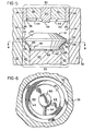
- lower die element 32 defines a second cavity 48 and a second outer shoulder 50 extending circumferentially around the second cavity 48, as illustrated in Fig. 6.
- the second, outer shoulder 50 has inner and outer diameters substantially equal to the inner and outer diameters, respectively, of the first outer shoulder 46.
- a sleeve 52 is provided for receiving the upper die element 30 and the lower die element 32.
- Sleeve 52 has an inner diameter substantially equal to the outer diameter of the first and second outer shoulders 46 and 50.
- the upper die element 30 and the lower die element 32 are positioned in the sleeve as shown in Fig. 5 with the first and second outer shoulders 46 and 50 in direct opposition whereby shoulders 46 and 50 and sleeve 52 define an annular space 54.
- the billet 12 is placed in the sleeve 52 between the upper die element 30 and the lower die element 32, as shown in Fig. 5, such that the parts of the upper and lower portions 24 and 26 of greatest diameter, as well as the rim 22, extend into the annular space 54.
- the edge 56 between the first outer shoulder 46 and the first cavity 44 contacts the upper frusto-conical portion 24 along a line extending circumferentially around portion 24.
- the edge 58 between the second outer shoulder 50 and the second cavity 48 contacts the lower frusto-conical portion 26 along a line extending circumferentially around portion 26.
- the billet 12 is cold formed into the first and second cavities 44 and 48, so as to form the metal part 10 from billet 12 in a single forming operation.
- sleeve 52 and lower die element 32 are illustrated as stationary and upper die element 30 is illustrated as being axially moveable, upper die element 30 could be held stationary with relative movement between the die elements being accomplished by axial movement of lower die element 32.
- the portion of the billet 12 from which the annular flange 14 is to be extruded is generally pill-shaped, that is, tapered in thickness outwardly toward a circumferential rim, the shoulders 46 and 50 do not contact the billet at the initiation of the radial extrusion flow 60.
- the extruding material does not apply an outward force to surfaces 46 and 50 by virtue of the sliding friction produced by the movement of the metal to the surfaces 46 and 50.
- the forming force which must be applied to the die element 30, therefore, is less than would be the case if a billet of a different shape were utilized.
- the stress applied to the die elements is reduced and breakage of these elements is materially reduced.
- the lower die element 32 defines a central pedestal 62 in the bottom of second cavity 48 and a raised rib 64 extending radially outward from the central pedestal 62, as shown best in Fig. 6.
- the movement of the upper and lower die elements 30 and 32 toward each other produces cold forming of the billet 10 into the second cavity 48 and formation of the central recess 16 and the slot 18 extending radially outward.
- central pedestal 66 is provided in the top of the first cavity 44.
- the movement of the upper and lower die elements 30 and 32 toward each other produces cold forming of the billet into the first cavity 44 and formation of the central recess 20 on the top side of the metal part 10.
- the metal part 10 produced in this one operation requires virtually no further manufacturing processes. There is very little scrap produced and none of the billet material is wasted in needless subsequent machining operations.
Landscapes
- Engineering & Computer Science (AREA)
- Mechanical Engineering (AREA)
- Physics & Mathematics (AREA)
- Condensed Matter Physics & Semiconductors (AREA)
- General Physics & Mathematics (AREA)
- Manufacturing & Machinery (AREA)
- Computer Hardware Design (AREA)
- Microelectronics & Electronic Packaging (AREA)
- Power Engineering (AREA)
- Forging (AREA)
Priority Applications (3)
| Application Number | Priority Date | Filing Date | Title |
|---|---|---|---|
| GB08511279A GB2158381B (en) | 1984-05-07 | 1985-05-03 | Method of forming a metal part having an annular flange |
| EP19850303985 EP0204043B1 (fr) | 1985-06-05 | 1985-06-05 | Procédé de fabrication d'une pièce métallique présentant une bride annulaire |
| DE8585303985T DE3583681D1 (de) | 1985-06-05 | 1985-06-05 | Verfahren zur herstellung eines metallwerkstueckes mit einem ringfoermigen flansch. |
Applications Claiming Priority (1)
| Application Number | Priority Date | Filing Date | Title |
|---|---|---|---|
| EP19850303985 EP0204043B1 (fr) | 1985-06-05 | 1985-06-05 | Procédé de fabrication d'une pièce métallique présentant une bride annulaire |
Publications (3)
| Publication Number | Publication Date |
|---|---|
| EP0204043A2 true EP0204043A2 (fr) | 1986-12-10 |
| EP0204043A3 EP0204043A3 (en) | 1988-07-20 |
| EP0204043B1 EP0204043B1 (fr) | 1991-07-31 |
Family
ID=8194250
Family Applications (1)
| Application Number | Title | Priority Date | Filing Date |
|---|---|---|---|
| EP19850303985 Expired - Lifetime EP0204043B1 (fr) | 1984-05-07 | 1985-06-05 | Procédé de fabrication d'une pièce métallique présentant une bride annulaire |
Country Status (2)
| Country | Link |
|---|---|
| EP (1) | EP0204043B1 (fr) |
| DE (1) | DE3583681D1 (fr) |
Citations (3)
| Publication number | Priority date | Publication date | Assignee | Title |
|---|---|---|---|---|
| US1373726A (en) * | 1918-01-17 | 1921-04-05 | Mueller Metals Company | Method of and die for producing forgings |
| GB717163A (en) * | 1951-05-02 | 1954-10-20 | Omes Ltd | Improvements in or relating to the manufacture of turbine rotors |
| US4362043A (en) * | 1975-09-17 | 1982-12-07 | Hanson Thomas A | Pipe unions |
-
1985
- 1985-06-05 DE DE8585303985T patent/DE3583681D1/de not_active Expired - Fee Related
- 1985-06-05 EP EP19850303985 patent/EP0204043B1/fr not_active Expired - Lifetime
Patent Citations (3)
| Publication number | Priority date | Publication date | Assignee | Title |
|---|---|---|---|---|
| US1373726A (en) * | 1918-01-17 | 1921-04-05 | Mueller Metals Company | Method of and die for producing forgings |
| GB717163A (en) * | 1951-05-02 | 1954-10-20 | Omes Ltd | Improvements in or relating to the manufacture of turbine rotors |
| US4362043A (en) * | 1975-09-17 | 1982-12-07 | Hanson Thomas A | Pipe unions |
Also Published As
| Publication number | Publication date |
|---|---|
| DE3583681D1 (de) | 1991-09-05 |
| EP0204043A3 (en) | 1988-07-20 |
| EP0204043B1 (fr) | 1991-07-31 |
Similar Documents
| Publication | Publication Date | Title |
|---|---|---|
| CA1186875A (fr) | Methode et dispositif de faconnage d'un connecteur electrique | |
| US5363714A (en) | Gear product | |
| US4607514A (en) | Method of forming a metal part having an annular flange | |
| US3377700A (en) | Method of making electrical contact member | |
| EP0204043A2 (fr) | Procédé de fabrication d'une pièce métallique présentant une bride annulaire | |
| JP2755716B2 (ja) | 複列玉軸受外輪素形材の鍛造方法 | |
| JPH0566215B2 (fr) | ||
| GB2158381A (en) | Method of forming a metal part having an annular flange | |
| US4531396A (en) | Forging die package | |
| JPH1177218A (ja) | 鍛造用金型装置 | |
| US3200226A (en) | Electrical contact member having a raised cup shaped work-hardened area | |
| JPH0899145A (ja) | テーパリングの鍛造方法 | |
| JPH1058073A (ja) | 複列軸受の製造方法および装置 | |
| JPH0518663B2 (fr) | ||
| US4132105A (en) | Method of making a locking collar for an antifriction bearing assembly | |
| JPH05277615A (ja) | 転がり軸受の軌道輪製造方法 | |
| JPH07144247A (ja) | 段付き部品の鍛造金型及び段付き部品の鍛造方法 | |
| JPS62183931A (ja) | ボ−ルスタツドの製造方法 | |
| JP2648902B2 (ja) | 口金ピンの製造方法 | |
| JPH0270350A (ja) | 超薄肉フィンを有する鍛造品の製造用型及び該型を用いた鍛造品の製造方法 | |
| JP2620162B2 (ja) | 鍛造金型の成形方法 | |
| JP2782882B2 (ja) | 中空部材の製造方法 | |
| JPH01262038A (ja) | 輪付きボルトの製造方法 | |
| CA1077688A (fr) | Methode de fabrication d'une piece polaire de generatrice | |
| JPH0588737U (ja) | 後方押出し型冷間鍛造装置 |
Legal Events
| Date | Code | Title | Description |
|---|---|---|---|
| PUAI | Public reference made under article 153(3) epc to a published international application that has entered the european phase |
Free format text: ORIGINAL CODE: 0009012 |
|
| AK | Designated contracting states |
Kind code of ref document: A2 Designated state(s): BE CH DE FR LI NL |
|
| PUAL | Search report despatched |
Free format text: ORIGINAL CODE: 0009013 |
|
| AK | Designated contracting states |
Kind code of ref document: A3 Designated state(s): BE CH DE FR LI NL |
|
| 17P | Request for examination filed |
Effective date: 19890113 |
|
| 17Q | First examination report despatched |
Effective date: 19900205 |
|
| GRAA | (expected) grant |
Free format text: ORIGINAL CODE: 0009210 |
|
| AK | Designated contracting states |
Kind code of ref document: B1 Designated state(s): BE CH DE FR LI NL |
|
| REF | Corresponds to: |
Ref document number: 3583681 Country of ref document: DE Date of ref document: 19910905 |
|
| ET | Fr: translation filed | ||
| PLBE | No opposition filed within time limit |
Free format text: ORIGINAL CODE: 0009261 |
|
| STAA | Information on the status of an ep patent application or granted ep patent |
Free format text: STATUS: NO OPPOSITION FILED WITHIN TIME LIMIT |
|
| 26N | No opposition filed | ||
| PGFP | Annual fee paid to national office [announced via postgrant information from national office to epo] |
Ref country code: FR Payment date: 19960515 Year of fee payment: 12 |
|
| PGFP | Annual fee paid to national office [announced via postgrant information from national office to epo] |
Ref country code: DE Payment date: 19960528 Year of fee payment: 12 Ref country code: BE Payment date: 19960528 Year of fee payment: 12 |
|
| PGFP | Annual fee paid to national office [announced via postgrant information from national office to epo] |
Ref country code: NL Payment date: 19960529 Year of fee payment: 12 Ref country code: CH Payment date: 19960529 Year of fee payment: 12 |
|
| PG25 | Lapsed in a contracting state [announced via postgrant information from national office to epo] |
Ref country code: LI Free format text: LAPSE BECAUSE OF NON-PAYMENT OF DUE FEES Effective date: 19970630 Ref country code: CH Free format text: LAPSE BECAUSE OF NON-PAYMENT OF DUE FEES Effective date: 19970630 Ref country code: BE Effective date: 19970630 |
|
| BERE | Be: lapsed |
Owner name: THE NIPPERT CY Effective date: 19970630 |
|
| PG25 | Lapsed in a contracting state [announced via postgrant information from national office to epo] |
Ref country code: NL Effective date: 19980101 |
|
| REG | Reference to a national code |
Ref country code: CH Ref legal event code: PL |
|
| PG25 | Lapsed in a contracting state [announced via postgrant information from national office to epo] |
Ref country code: FR Free format text: LAPSE BECAUSE OF NON-PAYMENT OF DUE FEES Effective date: 19980227 |
|
| NLV4 | Nl: lapsed or anulled due to non-payment of the annual fee |
Effective date: 19980101 |
|
| PG25 | Lapsed in a contracting state [announced via postgrant information from national office to epo] |
Ref country code: DE Free format text: LAPSE BECAUSE OF NON-PAYMENT OF DUE FEES Effective date: 19980303 |
|
| REG | Reference to a national code |
Ref country code: FR Ref legal event code: ST |
|
| REG | Reference to a national code |
Ref country code: FR Ref legal event code: ST |