EP0203656A2 - Unitary separator-spacer for electrochemical cell, and electrochemical cell construction using such spacer(s) - Google Patents
Unitary separator-spacer for electrochemical cell, and electrochemical cell construction using such spacer(s) Download PDFInfo
- Publication number
- EP0203656A2 EP0203656A2 EP86200846A EP86200846A EP0203656A2 EP 0203656 A2 EP0203656 A2 EP 0203656A2 EP 86200846 A EP86200846 A EP 86200846A EP 86200846 A EP86200846 A EP 86200846A EP 0203656 A2 EP0203656 A2 EP 0203656A2
- Authority
- EP
- European Patent Office
- Prior art keywords
- unit
- electrodes
- projections
- connector
- web
- Prior art date
- Legal status (The legal status is an assumption and is not a legal conclusion. Google has not performed a legal analysis and makes no representation as to the accuracy of the status listed.)
- Granted
Links
Images


Classifications
-
- C—CHEMISTRY; METALLURGY
- C25—ELECTROLYTIC OR ELECTROPHORETIC PROCESSES; APPARATUS THEREFOR
- C25B—ELECTROLYTIC OR ELECTROPHORETIC PROCESSES FOR THE PRODUCTION OF COMPOUNDS OR NON-METALS; APPARATUS THEREFOR
- C25B13/00—Diaphragms; Spacing elements
- C25B13/02—Diaphragms; Spacing elements characterised by shape or form
-
- H—ELECTRICITY
- H01—ELECTRIC ELEMENTS
- H01M—PROCESSES OR MEANS, e.g. BATTERIES, FOR THE DIRECT CONVERSION OF CHEMICAL ENERGY INTO ELECTRICAL ENERGY
- H01M50/00—Constructional details or processes of manufacture of the non-active parts of electrochemical cells other than fuel cells, e.g. hybrid cells
- H01M50/40—Separators; Membranes; Diaphragms; Spacing elements inside cells
- H01M50/463—Separators, membranes or diaphragms characterised by their shape
-
- C—CHEMISTRY; METALLURGY
- C25—ELECTROLYTIC OR ELECTROPHORETIC PROCESSES; APPARATUS THEREFOR
- C25B—ELECTROLYTIC OR ELECTROPHORETIC PROCESSES FOR THE PRODUCTION OF COMPOUNDS OR NON-METALS; APPARATUS THEREFOR
- C25B9/00—Cells or assemblies of cells; Constructional parts of cells; Assemblies of constructional parts, e.g. electrode-diaphragm assemblies; Process-related cell features
- C25B9/70—Assemblies comprising two or more cells
- C25B9/73—Assemblies comprising two or more cells of the filter-press type
-
- H—ELECTRICITY
- H01—ELECTRIC ELEMENTS
- H01M—PROCESSES OR MEANS, e.g. BATTERIES, FOR THE DIRECT CONVERSION OF CHEMICAL ENERGY INTO ELECTRICAL ENERGY
- H01M10/00—Secondary cells; Manufacture thereof
- H01M10/36—Accumulators not provided for in groups H01M10/05-H01M10/34
- H01M10/365—Zinc-halogen accumulators
-
- H—ELECTRICITY
- H01—ELECTRIC ELEMENTS
- H01M—PROCESSES OR MEANS, e.g. BATTERIES, FOR THE DIRECT CONVERSION OF CHEMICAL ENERGY INTO ELECTRICAL ENERGY
- H01M4/00—Electrodes
- H01M4/02—Electrodes composed of, or comprising, active material
- H01M4/64—Carriers or collectors
-
- H—ELECTRICITY
- H01—ELECTRIC ELEMENTS
- H01M—PROCESSES OR MEANS, e.g. BATTERIES, FOR THE DIRECT CONVERSION OF CHEMICAL ENERGY INTO ELECTRICAL ENERGY
- H01M8/00—Fuel cells; Manufacture thereof
- H01M8/02—Details
-
- Y—GENERAL TAGGING OF NEW TECHNOLOGICAL DEVELOPMENTS; GENERAL TAGGING OF CROSS-SECTIONAL TECHNOLOGIES SPANNING OVER SEVERAL SECTIONS OF THE IPC; TECHNICAL SUBJECTS COVERED BY FORMER USPC CROSS-REFERENCE ART COLLECTIONS [XRACs] AND DIGESTS
- Y02—TECHNOLOGIES OR APPLICATIONS FOR MITIGATION OR ADAPTATION AGAINST CLIMATE CHANGE
- Y02E—REDUCTION OF GREENHOUSE GAS [GHG] EMISSIONS, RELATED TO ENERGY GENERATION, TRANSMISSION OR DISTRIBUTION
- Y02E60/00—Enabling technologies; Technologies with a potential or indirect contribution to GHG emissions mitigation
- Y02E60/10—Energy storage using batteries
-
- Y—GENERAL TAGGING OF NEW TECHNOLOGICAL DEVELOPMENTS; GENERAL TAGGING OF CROSS-SECTIONAL TECHNOLOGIES SPANNING OVER SEVERAL SECTIONS OF THE IPC; TECHNICAL SUBJECTS COVERED BY FORMER USPC CROSS-REFERENCE ART COLLECTIONS [XRACs] AND DIGESTS
- Y02—TECHNOLOGIES OR APPLICATIONS FOR MITIGATION OR ADAPTATION AGAINST CLIMATE CHANGE
- Y02E—REDUCTION OF GREENHOUSE GAS [GHG] EMISSIONS, RELATED TO ENERGY GENERATION, TRANSMISSION OR DISTRIBUTION
- Y02E60/00—Enabling technologies; Technologies with a potential or indirect contribution to GHG emissions mitigation
- Y02E60/30—Hydrogen technology
- Y02E60/50—Fuel cells
-
- Y—GENERAL TAGGING OF NEW TECHNOLOGICAL DEVELOPMENTS; GENERAL TAGGING OF CROSS-SECTIONAL TECHNOLOGIES SPANNING OVER SEVERAL SECTIONS OF THE IPC; TECHNICAL SUBJECTS COVERED BY FORMER USPC CROSS-REFERENCE ART COLLECTIONS [XRACs] AND DIGESTS
- Y02—TECHNOLOGIES OR APPLICATIONS FOR MITIGATION OR ADAPTATION AGAINST CLIMATE CHANGE
- Y02P—CLIMATE CHANGE MITIGATION TECHNOLOGIES IN THE PRODUCTION OR PROCESSING OF GOODS
- Y02P70/00—Climate change mitigation technologies in the production process for final industrial or consumer products
- Y02P70/50—Manufacturing or production processes characterised by the final manufactured product
Definitions
- This invention relates to an integral separator and spacer unit for use in an electrochemical cell, e.g. an improved elecrochemical cell construction which can be useful in vehicular battery systems.
- the present invention seeks to provide an integral separator and spacer unit for use in a new electrochemical cell construction which reduces the initial costs and extends operating life for a battery system through the utilization of new manufacturing techniques, new weight-reducing materials and new integration of components.
- the subject invention is useful in the manufacture, construction and assembly of many different kinds of electrochemical cells, and the invention should be interpreted as not being limited to a specific system.
- the above-mentioned battery system is of particular interest because of its low cost and availability of reactants, its high cell voltage and its high degree of reversibility.
- GB-A-1160587 discloses an electrochemical cell having an ion-permselective resin membrane having projections formed on each face.
- the projections may have the form of pebbles, ribs, etc., and projections on one face are opposite projections on the other face.
- the projections are of the same material as the membrane.
- the edge region of the membrane is flat so that a separable spacing frame can form a liquid-tight seal therewith.
- the frame has apertures for the passage of fluid into the space defined between the membrane and an adjacent electrode.
- FR-A-1504315 discloses a fuel cell comprising an exchange membrane extending across the space surrounded by a frame which is thicker than the membrane.
- the membrane has holes therethrough to receive the two halves of a spacing member extending on both sides of the membrane when mutually engaged through the holes by a push-fit action.
- FR-A-1547710 discloses an electrochemical cell, such as a fuel cell, having a membrane of selective permeability which is embossed, preferably by hot-pressing between dies, so as to have hollows and projections.
- the membrane has a low electrical resistivity.
- U.S.-A-4,218,521 discloses a zinc-halide battery construction comprising a microporous separator having spacing members on opposite faces to define catholyte and anolyte spaces.
- the spacing members may be similar in shape on both faces of the separator and may have the form of discrete projections.
- the spacing members are of electrically non-conductive material and may be integral with their supporting web.
- DE-A-2627143 (equivalent to GB-A-1548597) discloses a porous separator for an electrochemical cell which has been stamped or pressed to have projections on each side.
- CH-A-119,558 discloses a porous ebonite membrane supported in a surrounding non-porous ebonite frame which may be integral with the membrane.
- the frame may be thicker than the membrane and the membrane may be ribbed.
- the present invention provides an integral separator and spacer unit for use in an electrochemical cell having electrodes and through which cell, during operation, a circulating electrolyte flows in contact with the electrodes, the said unit being in the form of a sheet disposable between adjacent pairs of electrodes and comprising a frame disposed about a non-perforated microporous web which is thinner than the frame in order to define or form either internal compartments or recesses forming at least part of such internal compartments between the unit and the adjacent electrodes when assembled with the latter so that circulating electrolyte can flow about said electrodes, said web being able to provide ionic communication between adjacent compartments of the cell, characterised in that each face of the web has a pluraliaty of discrete pebble-shaped and/or rod-shaped projections which are ionically either less conductive or substantially non-conductive for maintaining a spaced compartmental distance between said unit and adjacent electrodes, substantially all of said projections on one face of the web being directly opposite corresponding projections on the other face thereof, the web being
- the frame has a connector which is cooperable with a connector of an adjacent frame, when the electrochemical cell is assembled, for the passage of electrolyte through the assembled electrochemical cell, and a channel in the wall of each connector for the passage of electrolyte from one connector into a compartment and via the channel into another connector.
- each connector is of the male-female type, the male part being adapted to be received in the female part of a connector of another unit on one side and the female part being adapted to receive the male part of a connector of a further unit on the opposite side.
- the frame is overmolded around the edges of the web.
- the projections have non-ionically conductive caps thereon or thereto.
- the projections may be, e.g., diamond or rhombus shaped, and they may be of a different material from the material of the web.
- the projections are substantially non-porous.
- the invention also provides an electrochemical construction comprising at least one stack of cells each comprised of an integral separator and spacer unit, as described herein, disposed between a pair of electrodes.
- each electrode is comprised of a plastics sheet having a coextruded electrically-conductive mid-portion and electrically non-conductive relatively narrow side-portions on no more than two opposite sides of the mid-portion.
- the spacer units and the electrodes are assembled into a stack of alternate spacer units and electrodes by hollow connectors associated with the spacer units, each connector of one unit having a male portion of the respective connector received in a female portion of the connector of an adjacent spacer unit to form fluid conduits for said cells.
- adjacent spacer units and electrodes define compartments or spaces in which electrolyte can be received and/or can flow, and preferably, each hollow connector has a channel or orifice in the wall thereof providing communication with a respective compartment or space for the passage of electrolyte through the compartment or space to and/or from the interior of the hollow connectors.
- the integral separator-spacer comprises a microporous sheet, which provides ionic communication between adjacent compartments of each cell.
- a web surface on each side of the microporous sheet is covered with projections for maintaining a spaced compartmental distance between said separator-spacer and said adjacent electrodes.
- the projections on one web surface are directly opposite corresponding projections on the other web surface of the sheet in order to provide a greater structural integrity to the sheet in its capacity to maintain a spaced distance between electrodes.
- the projections can be pebble or rod-shaped or a combination of pebble and rod-shapes.
- the separator-spacer has a non-porous border substantially surrounding the mircroporous sheet, which microporous sheet can be ion-selective.
- the electrodes have narrow non-conductive top and bottom side portion strips with respect to their larger conductive mid-portions.
- the electrodes can be made monopolar or bipolar, but can be specifically bipolar in order to operate in a zinc-bromine system, for example.
- the non-conductive side strips can be made of polypropylene, polyethylene, or copolymers thereof, while the conductive mid-portion comprises a carbon-containing polyolefin. More specifically, the conductive mid-portion comprises by weight 100 parts polyolefin, 25 parts carbon, 5 parts each pitch fiber and glass fiber and 1 part fumed silica powder.
- the extruded material can be hot formed and can be dimpled.
- the electrochemical construction can be provided with a protective current in order to reduce or eliminate parasitic shunt currents in common electrolyte systems of this type.
- the zinc-bromine electrochemical system of the invention also features a leak and impact resistant construction comprising:
- the first electrolyte is generally the catholyte for the system, while the second electrolyte is generally the anolyte.
- the bromine-rich phase is a non-aqueous phase which separates from the aqueous catholyte and contains bromine complexing agents.
- the compartment and casing materials are generally comprised of chemically inert, impact resistant plastics.
- FIG. 1 a schematic diagram of a typical circulating, bipolar zinc-bromine system is shown. This system can benefit from the inventive construction which will be hereinafter described with reference to- Figures 2 through 7.
- the zinc-bromine system of Figure 1 comprises two electrolytes which are circulated through separate compartments 8, 9 respectively, of the cell 10.
- An anolyte which is generally stored in reservoir 11 is pumped via pump 12 through compartment 8 and loop 13, generally referred to as the anode loop.
- a catholyte which is generally stored in reservoir 14 is pumped via pump 15 through compartment 9 and loop 16, generally referred to as the cathode loop.
- the zinc-bromine system is also a two phase system, in that the catholyte has bromine complexing agents and is comprised of a first aqueous phase and a second, non-aqueous, bromine-rich phase.
- the bromine-rich (complexed) phase tends to separate at the bromine active electrode 17 from the aqueous catholyte.
- This non-aqueous phase is stored in the reservoir 14, as illustrated schematically by shaded portion 14a.
- a separator 18 delinates and defines the boundary between the anolyte and cathode compartments 8 and 9, respectively.
- the separator 18 is a membrane which prevents or binders movement of anions such as the bromide and tribromide ions from cathode compartment 9 to the anode compartment 8.
- the zinc active electrode 19 and the bromine active electrode 17 are opposite sides of the same electrode structure.
- the zinc-bromine system can be made more practicable by integrating and improving various components of Figure 1, as will be hereinafter explained with respect to the inventive construction shown in Figures 2 through 7. Where applicable within the description, like components may have similar numerical designations for the sake of brevity.
- FIG. 2 an improved electrochemical system is shown in a schematic perspective view.
- the improved system utilizes an integrated two-leaved separator-spacer and electrode forming a portion of a stack of cells, as depicted in the exploded view of Figure 3.
- the electrochemical system of Figure 2 comprises a battery stack 25 which in turn is comprised of a plurality of cells 10, each having two plates, as shown in Figure 3.
- the separator-spacer has two functions combined in a single sheet. The first purpose is that of the separator 18 in Figure 1, i.e. to provide fluid communication between compartments as a membrane. A more detailed description of this function can be obtained from the above-mentioned U.S. Patent No. 4,105,829; issued August 8, 1978; and also from U.S. Patent No. 4,259,417; issued March 31, 1981 for an "Ionic Barrier", to inventors: R. J. Bellows and P. G. Grimes.
- the second function of sheet 28 is to space the. sheet 28 from the adjacent electrode sheets 29 so as to create respective anolyte and catholyte compartments 8 and 9 ( Figure 1).
- the separator-spacer sheet 28 has a microporous mid-portion surface 30 which is recessed from the non-porous surface 31 of the sides, as shown in more detail in Figures 6 and 6a.
- the projections 32 on the microporous mid-portion surfaces are designed to maintain a spaced compartmental distance between the separator-spacer surface 30 and the flat conductive surfaces 33 of adjacent electrode sheet 29.
- the projections 32 provide structural means against collapse of surfaces 33 upon surfaces 30 and vice versa.
- the projections 32 on one side 30 of sheet 28 are diametrically opposite corresponding projections 32 on the opposite side 30 of sheet 28 as clearly illustrated in Figure 6a. This is done, to provide a greater strength against distortion of surfaces 33 upon surfaces 30.
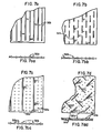
- the projections 32 usually are designed as pebbles as depicted by arrows 32a in Figure 6a, and as also shown in Figures 7cc and 7dd, etc.
- projections 32 may also be designed with a rod-shape as depicted in Figures 7a, 7aa and 7b, 7bb; by arrows 32b.
- the projections 32 may also be a combination of pebble and rod-shaped protuberances as depicted in Figures 7c, 7cc and 7d, 7dd.
- the mid-portion of the separator-spacer sheet 28 can be comprised of a microporous membrane material known as Daramic R , Series HW-0835, which is made by W. R. Grace Co., Polyfibron Division, Cambridge, Massachusetts.
- the raised side borders 31 of non-porous material may be any moldable plastic.
- the plastic of borders 31 is typycally overmolded around the separator-spacer insert by injection molding, as can be seen from Figure 6a.
- Sheets 28 and 29 are assembled by means of hollow male/female connectors 40 shown in detail in Figures 6 and 6a.
- these hollow connectors 40 form electrolyte manifolds which supply compartments 8 and 9 with electrolyte via individual conduits or channels 60.
- the male/female connectors 40 of sheets 28 fit through the holes 41 ( Figures 4 and 4a) in adjacent sheets 29, and snap into mating connectors 40 in subsequently adjacent sheets 28.
- the electrode sheet 29 of Figures 4 and 4a is comprised of a coextruded sheet of plastic which has an electrically conductive mid-portion 33 and two side portions 37 of electrically non-conductive (insulating) plastic.
- the top and bottom side portions 37 are co- extruded "side-by-side” along with the mid-portion 33 to form a one piece continuous electrode sheet, which continuous sheet is then cut to specific lengths to form a plurality of smaller sheets 29.
- the edges 38 of sheet 29 may be undercut to improve electrical isolation in stack 25.
- the co-extrusion method 11 gives more uniformity in thickness, a stronger bonding between the insulating and conductive plastics, much desired flatness, and "electrode by yards' similar to dress fabrice. The fabrication cost is much lower because the process is continuous.
- a special formulation of carbon plastic is needed for mid-portion 33 of sheet 29 to provide good electrical conductivity, which still exhibit good extrudibility, good strength, and excellent anti-corrosive properties against bromine and zinc bromide in the electrolyte.
- the preferred composition of the conductive carbon plastic is covered by aforementioned U.S. Patent No. 4,169,816; issued October 2, 1979, to H.C. Tsien.
- This formulation gives good conductivity (1 to 2 ohm-cm in resistivity), good flex strength, low permeability inertness to bromine, good extrudibility, better weldability and less mold shrinkage.
- the conductive plastic is a mixture of 100 parts by weight of polyolefin copolymer, 25 parts by weight of special conductive carbon, 5 parts by weight each of carbon fiber and glass fiber, and 1 part by weight of fumed silica powder.
- Figures 5a, 5b and 5c are respective top, front and side views of an extrusion die used to fabricate the electrode sheet.
- the center extrusion die 47 receives conductive plastic from a horizontal extruder through conduit 46, while the side extrusion dies 48,.each receive non-conducting plastic from an overhead, vertical extruder via conduits 45a and 45b, respectively.
- the horizontal extruder for the black conductive plastic is a 2-1/2" screw with L/D of 30:1, while the vertical extruder for the opaque insulating plastic is a 1-1/2" dia. screw with L/D of 24:1.
- the melted insulating plastic enters into the die at 90 degrees from the vertical stream 45, divides into two steams 45a and 45b and flows into one left and one right separate "coat hangers" along side the main coat hanger 45.
- the die design is conventional, except that the side-by-side profile division is believed to be novel.
- the die is of split construction in order to facilitate any changes in the design and the ease of fabrication.
- the main die assembly consists of a lower die body 55, upper die body 56, flexible upper lip 57 and fixed lower lip 58.
- the die lip gap is ground to allow for the swell of plastics emerging out of the die. Lip gaps can be individually adjusted by screws 59 in conjunction with the nut bars 61.
- the two side plastics 62 and 63 close the two outsides of flow channels of the insulating plastics and give a box-like reinforcement.
- Adapter 64 provides connection to the main extruder. There are (16) cartridge heaters 65 and (4) band heaters 66 for heating the two streams of plastics. Temperatures are controlled through thermocouples and individual zone temperature controllers.
- the individual adjustment of the left and right streams 45a and 45b is made possible by ball headed adjusting screws 67 and locknut 68.
- Bushings 74 make good connection from valve blocks 75 to die block 56. All main parts of the die are made of A2 air hardening tool steel.
- the Bethelehem A2 air hardening steel has the following physical properties:
- the die cannot operate free from internal leakage between the insulating and conducting streams if the die is in the soft annealed condition.
- the hardened and reground die eliminates internal leakage.
- Exxon homopolymer PP5011 and 5052 can match well with the conductive plastic. They came out of the die with no wrinkles, the sheets were flat and uniform.
- any polyethylene or polypropylene for side portions 37 can be a good match with the conductive plastic mid-portion 33, because the basic material used in the conductive plastic is the copolymer of the two.
- the melting points are in the range of 325 to 3750F. Therefore, approximately 400°F is a proper temperature in range for the two streams to meet. Head pressures are 1500 to 1800 psi. These conditions made a good bond at the bonding line.
- the extrusion speed can be around 20 ft./minute to 90 ft./minute.
- Powder of activated carbon can be sprayed on one face of the carbon plastic as the sheet is emerging from the die and before the sheet is pinched by the cold nip rolls. The powder spray is limited in the conductive area.
- nip rolls can be changed from polished chrome- plated surface to Teflon coated and rubber rolls. It is also possible to replace nip rolls with dimpling rolls, so that cavities or special flow patterns can be formed on one or both faces of the co-extruded sheet.
- the hot forming rolls can make repeated patterns of design indentations in the electrode, if so desired.
- Figure 5 is a schematic perspective view of the continuous electrode sheet emerging from the split die illustrated in Figures 5a, 5b and 5c.
- the various compartments can be nested with the bromine-containing compartment 50 being the most internal compartment.
- the bromine compartment 50 is surrounded by the catholyte- containing compartment 51, which in turn is surrounded by the anolyte-containing compartment 52.
- Compartments 50, 51, and 52 are all enclosed by outer casing 53.
- Shunt currents can be eliminated along formed manifolds (connectors 40) by means of applying a protective current along these electrolyte carrying conduits, in accordance with the teachings expressed in aforementioned U.S. Patent No. 4,197,169 issued April 8, 1980 to M. Zahn, P. G. Grimes and R. J. Bellows.
- the two-leaved electrochemical cell construction of this invention reduces parts and is easier to fabricate and assemble than prior systems of this kind. Further modifications to the invention may occur to those skilled practitioners of this art. Such modifications have not been described for the sake of brevity.
Landscapes
- Chemical & Material Sciences (AREA)
- Chemical Kinetics & Catalysis (AREA)
- Electrochemistry (AREA)
- General Chemical & Material Sciences (AREA)
- Engineering & Computer Science (AREA)
- Materials Engineering (AREA)
- Metallurgy (AREA)
- Organic Chemistry (AREA)
- Manufacturing & Machinery (AREA)
- Life Sciences & Earth Sciences (AREA)
- Sustainable Development (AREA)
- Sustainable Energy (AREA)
- Hybrid Cells (AREA)
Abstract
Description
- This invention relates to an integral separator and spacer unit for use in an electrochemical cell, e.g. an improved elecrochemical cell construction which can be useful in vehicular battery systems.
- In recent times, the use of light weight battery materials and cost efficient battery constructions have been of prime interest to the automotive and battery industries. In particular, cost-effective battery designs are of paramount importance for electric vehicular systems. For electric vehicles and other bulk energy storage applications, cost justification of a battery system is highly sensitive to the initial battery cost and to the life-cycle cost. The present invention seeks to provide an integral separator and spacer unit for use in a new electrochemical cell construction which reduces the initial costs and extends operating life for a battery system through the utilization of new manufacturing techniques, new weight-reducing materials and new integration of components.
- A new cell design and construction has resulted from the achievement of the above objectives, which design and construction features amongst other novelties:
- 1. The integral separator and spacer to reduce space, parts and cost.
- 2. A reduction in gas entrapment with the use of the new separator-spacer design.
- 3. An integral conductive/non- conductive (dielectric) coextruded plastic electrode which is both light weight and inexpensive to manufacture.
- 4. Reduction and/or elimination of parasitic shunt currents.
- 5. Male/female stacking and integration of parts and conduits to provide ease and compactness of assembly.
- 6. A two-piece interleaved bipolar battery assembly which is more compact, light weight, leak-proof, easy to assemble and low cost.
- 7. A safer battery design and construction which reduces the possibility of spilling corrosive materials should compartments housing these materials rupture.
- The subject invention is useful in the manufacture, construction and assembly of many different kinds of electrochemical cells, and the invention should be interpreted as not being limited to a specific system.
- It is of particular interest for use in a circulating zinc-bromine battery, constructed in accordance with the teachings advanced in the aforementioned U.S. Patent to: Agustin F. Venero, entitled: Metal Halogen Batteries and Method of Operating Same, Patent No. 4,105,829, issued: August 8, 1978, and assigned to the present assignee.
- The above-mentioned battery system is of particular interest because of its low cost and availability of reactants, its high cell voltage and its high degree of reversibility.
- To the best of our knowledge and belief, the various novelties presented and described herein, are completely new within the art of electrochemical system design and construction. The skilled practitioner will gain a particular appreciation of the unique ideas and concepts advanced herein.
- GB-A-1160587 discloses an electrochemical cell having an ion-permselective resin membrane having projections formed on each face. The projections may have the form of pebbles, ribs, etc., and projections on one face are opposite projections on the other face. The projections are of the same material as the membrane. The edge region of the membrane is flat so that a separable spacing frame can form a liquid-tight seal therewith. The frame has apertures for the passage of fluid into the space defined between the membrane and an adjacent electrode.
- FR-A-1504315 discloses a fuel cell comprising an exchange membrane extending across the space surrounded by a frame which is thicker than the membrane. The membrane has holes therethrough to receive the two halves of a spacing member extending on both sides of the membrane when mutually engaged through the holes by a push-fit action.
- FR-A-1547710 discloses an electrochemical cell, such as a fuel cell, having a membrane of selective permeability which is embossed, preferably by hot-pressing between dies, so as to have hollows and projections. The membrane has a low electrical resistivity.
- U.S.-A-4,218,521 discloses a zinc-halide battery construction comprising a microporous separator having spacing members on opposite faces to define catholyte and anolyte spaces. The spacing members may be similar in shape on both faces of the separator and may have the form of discrete projections. The spacing members are of electrically non-conductive material and may be integral with their supporting web.
- DE-A-2627143 (equivalent to GB-A-1548597) discloses a porous separator for an electrochemical cell which has been stamped or pressed to have projections on each side.
- CH-A-119,558 discloses a porous ebonite membrane supported in a surrounding non-porous ebonite frame which may be integral with the membrane. The frame may be thicker than the membrane and the membrane may be ribbed.
- The present invention provides an integral separator and spacer unit for use in an electrochemical cell having electrodes and through which cell, during operation, a circulating electrolyte flows in contact with the electrodes, the said unit being in the form of a sheet disposable between adjacent pairs of electrodes and comprising a frame disposed about a non-perforated microporous web which is thinner than the frame in order to define or form either internal compartments or recesses forming at least part of such internal compartments between the unit and the adjacent electrodes when assembled with the latter so that circulating electrolyte can flow about said electrodes, said web being able to provide ionic communication between adjacent compartments of the cell, characterised in that each face of the web has a pluraliaty of discrete pebble-shaped and/or rod-shaped projections which are ionically either less conductive or substantially non-conductive for maintaining a spaced compartmental distance between said unit and adjacent electrodes, substantially all of said projections on one face of the web being directly opposite corresponding projections on the other face thereof, the web being preferably ion-selective. Preferably, the frame comprises a non-porous border substantially surrounding the microporous web.
- Preferably, the frame has a connector which is cooperable with a connector of an adjacent frame, when the electrochemical cell is assembled, for the passage of electrolyte through the assembled electrochemical cell, and a channel in the wall of each connector for the passage of electrolyte from one connector into a compartment and via the channel into another connector. Preferably, each connector is of the male-female type, the male part being adapted to be received in the female part of a connector of another unit on one side and the female part being adapted to receive the male part of a connector of a further unit on the opposite side.
- Preferably, the frame is overmolded around the edges of the web. Preferably, at least some of the projections have non-ionically conductive caps thereon or thereto. The projections may be, e.g., diamond or rhombus shaped, and they may be of a different material from the material of the web. Preferably, the projections are substantially non-porous.
- The invention also provides an electrochemical construction comprising at least one stack of cells each comprised of an integral separator and spacer unit, as described herein, disposed between a pair of electrodes.
- Preferably, each electrode is comprised of a plastics sheet having a coextruded electrically-conductive mid-portion and electrically non-conductive relatively narrow side-portions on no more than two opposite sides of the mid-portion.
- Preferably, the spacer units and the electrodes are assembled into a stack of alternate spacer units and electrodes by hollow connectors associated with the spacer units, each connector of one unit having a male portion of the respective connector received in a female portion of the connector of an adjacent spacer unit to form fluid conduits for said cells. Preferably, adjacent spacer units and electrodes define compartments or spaces in which electrolyte can be received and/or can flow, and preferably, each hollow connector has a channel or orifice in the wall thereof providing communication with a respective compartment or space for the passage of electrolyte through the compartment or space to and/or from the interior of the hollow connectors.
- The integral separator-spacer comprises a microporous sheet, which provides ionic communication between adjacent compartments of each cell. A web surface on each side of the microporous sheet is covered with projections for maintaining a spaced compartmental distance between said separator-spacer and said adjacent electrodes. The projections on one web surface are directly opposite corresponding projections on the other web surface of the sheet in order to provide a greater structural integrity to the sheet in its capacity to maintain a spaced distance between electrodes. The projections can be pebble or rod-shaped or a combination of pebble and rod-shapes.
- The separator-spacer has a non-porous border substantially surrounding the mircroporous sheet, which microporous sheet can be ion-selective.
- The electrodes have narrow non-conductive top and bottom side portion strips with respect to their larger conductive mid-portions. The electrodes can be made monopolar or bipolar, but can be specifically bipolar in order to operate in a zinc-bromine system, for example. The non-conductive side strips can be made of polypropylene, polyethylene, or copolymers thereof, while the conductive mid-portion comprises a carbon-containing polyolefin. More specifically, the conductive mid-portion comprises by weight 100 parts polyolefin, 25 parts carbon, 5 parts each pitch fiber and glass fiber and 1 part fumed silica powder. The extruded material can be hot formed and can be dimpled.
- The electrochemical construction can be provided with a protective current in order to reduce or eliminate parasitic shunt currents in common electrolyte systems of this type.
- The zinc-bromine electrochemical system of the invention also features a leak and impact resistant construction comprising:
- a first inner compartment for storing a bromine-rich phase;
- a second compartment substantially surrounding said first inner compartment and containing a first electrolyte for circulation through said cell;
- a third compartment substantially surrounding both said second and first compartments and containing a second electrolyte for circulation through said cell; and
- an outer casing substantially surrounding said first, second and third compartments.
- The first electrolyte is generally the catholyte for the system, while the second electrolyte is generally the anolyte. The bromine-rich phase is a non-aqueous phase which separates from the aqueous catholyte and contains bromine complexing agents.
- The compartment and casing materials are generally comprised of chemically inert, impact resistant plastics.
- It is an object of the present invention to provide a cost efficient electrochemical construction;
- It is another object of this invention to - provide an electrochemical construction which is light weight and compact;
- It is a further object of the invention to provide a new electrochemical system having a high voltage and cyclic-life.
- These and other objects of this invention will be better understood and will become more apparent with reference to the following detailed description considered in conjunction with the accompanying drawings.
-
- Figure 1 is a schematic diagram of a typical circulating zinc-bromine system which can benefit from the inventive construction shown in the following Figures 2 through 7.
- Figure 2 is a partially cutaway prospective view of a zinc-bromine system constructed in accordance with this invention;
- Figure 3 is an exploded perspective view of the two-sheet stack construction of a portion of a stack of cells of the electrochemical system of this invention;
- Figure 4 is a front view of the coextruded sheet electrode of the inventive construction shown in Figure 3;
- Figure 4a is a side view of the sheet electrode of Figure 4;
- Figure 5 is a perspective view of the electrode being extruded;
- Figures 5a, 5b and Sc are respective top, front and side views of the coextrusion die used to fabricate the sheet electrode shown in Figures 3, 4, and 4a;
- Figure 6 is a front view of the integral separator-spacer illustrated in the inventive construction of Figure 3;
- Figure 6a is a side view of the integral separator-spacer depicted in Figure 6;
- Figures 7a through 7d are illustrative of various designs for the projections depicted on the web surfaces of the sepatator-spacer shown in Figures 6 and 6a; and
- Figures 7aa through 7dd are side views of the projections depicted in respective Figures 7a through 7d.
- Referring to Figure 1, a schematic diagram of a typical circulating, bipolar zinc-bromine system is shown. This system can benefit from the inventive construction which will be hereinafter described with reference to-Figures 2 through 7. The zinc-bromine system of Figure 1 comprises two electrolytes which are circulated through
separate compartments cell 10. An anolyte which is generally stored in reservoir 11 is pumped viapump 12 throughcompartment 8 andloop 13, generally referred to as the anode loop. A catholyte which is generally stored inreservoir 14, is pumped viapump 15 throughcompartment 9 andloop 16, generally referred to as the cathode loop. - The zinc-bromine system is also a two phase system, in that the catholyte has bromine complexing agents and is comprised of a first aqueous phase and a second, non-aqueous, bromine-rich phase. The bromine-rich (complexed) phase tends to separate at the bromine
active electrode 17 from the aqueous catholyte. This non-aqueous phase is stored in thereservoir 14, as illustrated schematically by shaded portion 14a. - A
separator 18 delinates and defines the boundary between the anolyte andcathode compartments separator 18 is a membrane which prevents or binders movement of anions such as the bromide and tribromide ions fromcathode compartment 9 to theanode compartment 8. In a bipolar design, the zinc active electrode 19 and the bromineactive electrode 17 are opposite sides of the same electrode structure. - Further description of the zinc-bromine system can be obtained with reference to aforementioned U.S. Patent No. 4,105,829; issued August 8, 1978.
- The zinc-bromine system can be made more practicable by integrating and improving various components of Figure 1, as will be hereinafter explained with respect to the inventive construction shown in Figures 2 through 7. Where applicable within the description, like components may have similar numerical designations for the sake of brevity.
- Now referring to Figure 2, an improved electrochemical system is shown in a schematic perspective view. The improved system utilizes an integrated two-leaved separator-spacer and electrode forming a portion of a stack of cells, as depicted in the exploded view of Figure 3.
- The electrochemical system of Figure 2, comprises a
battery stack 25 which in turn is comprised of a plurality ofcells 10, each having two plates, as shown in Figure 3. One plate, according to the_invention, is an integral separator-spacer 28 and the other plate is anelectrode sheet 29. The separator-spacer has two functions combined in a single sheet. The first purpose is that of theseparator 18 in Figure 1, i.e. to provide fluid communication between compartments as a membrane. A more detailed description of this function can be obtained from the above-mentioned U.S. Patent No. 4,105,829; issued August 8, 1978; and also from U.S. Patent No. 4,259,417; issued March 31, 1981 for an "Ionic Barrier", to inventors: R. J. Bellows and P. G. Grimes. - The second function of
sheet 28 is to space the.sheet 28 from theadjacent electrode sheets 29 so as to create respective anolyte andcatholyte compartments 8 and 9 (Figure 1). The separator-spacer sheet 28 has a microporousmid-portion surface 30 which is recessed from thenon-porous surface 31 of the sides, as shown in more detail in Figures 6 and 6a. When the separator-spacer sheets 28 are pressed betweenelectrode sheets 29, thestack structure 25 is formed, as shown in Figure 2. Theprojections 32 on the microporous mid-portion surfaces are designed to maintain a spaced compartmental distance between the separator-spacer surface 30 and the flatconductive surfaces 33 ofadjacent electrode sheet 29. Theprojections 32 provide structural means against collapse ofsurfaces 33 uponsurfaces 30 and vice versa. Theprojections 32 on oneside 30 ofsheet 28 are diametrically oppositecorresponding projections 32 on theopposite side 30 ofsheet 28 as clearly illustrated in Figure 6a. This is done, to provide a greater strength against distortion ofsurfaces 33 uponsurfaces 30. Theprojections 32 usually are designed as pebbles as depicted byarrows 32a in Figure 6a, and as also shown in Figures 7cc and 7dd, etc. - These
projections 32 may also be designed with a rod-shape as depicted in Figures 7a, 7aa and 7b, 7bb; byarrows 32b. Theprojections 32 may also be a combination of pebble and rod-shaped protuberances as depicted in Figures 7c, 7cc and 7d, 7dd. - The design of these projections allow for an expeditious flow of electrolyte through the
compartments projections 32 within thecompartmental cavities - The mid-portion of the separator-
spacer sheet 28 can be comprised of a microporous membrane material known as DaramicR, Series HW-0835, which is made by W. R. Grace Co., Polyfibron Division, Cambridge, Massachusetts. The raised side borders 31 of non-porous material may be any moldable plastic. The plastic ofborders 31 is typycally overmolded around the separator-spacer insert by injection molding, as can be seen from Figure 6a. -
Sheets female connectors 40 shown in detail in Figures 6 and 6a. When thesheets stack 25, thesehollow connectors 40 form electrolyte manifolds which supplycompartments channels 60. - The male/
female connectors 40 ofsheets 28 fit through the holes 41 (Figures 4 and 4a) inadjacent sheets 29, and snap intomating connectors 40 in subsequentlyadjacent sheets 28. - The
electrode sheet 29 of Figures 4 and 4a is comprised of a coextruded sheet of plastic which has an electrically conductive mid-portion 33 and twoside portions 37 of electrically non-conductive (insulating) plastic. The top andbottom side portions 37 are co- extruded "side-by-side" along with the mid-portion 33 to form a one piece continuous electrode sheet, which continuous sheet is then cut to specific lengths to form a plurality ofsmaller sheets 29. Theedges 38 ofsheet 29 may be undercut to improve electrical isolation instack 25. - This "side-by-side" profile co-extrusion of insulating and conductive
plastic sheets - A special formulation of carbon plastic is needed for
mid-portion 33 ofsheet 29 to provide good electrical conductivity, which still exhibit good extrudibility, good strength, and excellent anti-corrosive properties against bromine and zinc bromide in the electrolyte. - The preferred composition of the conductive carbon plastic is covered by aforementioned U.S. Patent No. 4,169,816; issued October 2, 1979, to H.C. Tsien. This formulation gives good conductivity (1 to 2 ohm-cm in resistivity), good flex strength, low permeability inertness to bromine, good extrudibility, better weldability and less mold shrinkage.
- The conductive plastic is a mixture of 100 parts by weight of polyolefin copolymer, 25 parts by weight of special conductive carbon, 5 parts by weight each of carbon fiber and glass fiber, and 1 part by weight of fumed silica powder.
- Some of the other advantages of coextruding the
section - 1. Good bonding between the insulating and conductive plastics.
- 2. Maintaining width, flatness and thickness dimensions with the tolerances specified.
- 3. Clear and sharp boundary lines between
sections - Figures 5a, 5b and 5c are respective top, front and side views of an extrusion die used to fabricate the electrode sheet. The center extrusion die 47 receives conductive plastic from a horizontal extruder through
conduit 46, while the side extrusion dies 48,.each receive non-conducting plastic from an overhead, vertical extruder viaconduits - The horizontal extruder for the black conductive plastic is a 2-1/2" screw with L/D of 30:1, while the vertical extruder for the opaque insulating plastic is a 1-1/2" dia. screw with L/D of 24:1.
- The melted insulating plastic enters into the die at 90 degrees from the
vertical stream 45, divides into twosteams main coat hanger 45. The die design is conventional, except that the side-by-side profile division is believed to be novel. The die is of split construction in order to facilitate any changes in the design and the ease of fabrication. - The main die assembly consists of a
lower die body 55,upper die body 56, flexibleupper lip 57 and fixedlower lip 58. - The die lip gap is ground to allow for the swell of plastics emerging out of the die. Lip gaps can be individually adjusted by screws 59 in conjunction with the nut bars 61. The two
side plastics -
Adapter 64 provides connection to the main extruder. There are (16)cartridge heaters 65 and (4)band heaters 66 for heating the two streams of plastics. Temperatures are controlled through thermocouples and individual zone temperature controllers. - The individual adjustment of the left and
right streams screws 67 andlocknut 68.Bushings 74 make good connection from valve blocks 75 to dieblock 56. All main parts of the die are made of A2 air hardening tool steel. The Bethelehem A2 air hardening steel has the following physical properties:
- With the head pressures from the extruders well over 1000 psi, the die cannot operate free from internal leakage between the insulating and conducting streams if the die is in the soft annealed condition. The hardened and reground die eliminates internal leakage. Four different types of insulating plastics were tried, they are:

- Both Exxon homopolymer PP5011 and 5052 can match well with the conductive plastic. They came out of the die with no wrinkles, the sheets were flat and uniform.
- Theoretically, aside from previous considerations, any polyethylene or polypropylene for
side portions 37 can be a good match with the conductive plastic mid-portion 33, because the basic material used in the conductive plastic is the copolymer of the two. The melting points are in the range of 325 to 3750F. Therefore, approximately 400°F is a proper temperature in range for the two streams to meet. Head pressures are 1500 to 1800 psi. These conditions made a good bond at the bonding line. - Close match of melt indices is necessary in order to eliminate scallops formed at the joint of the two edges. The viscosities and velocities of the streams from the two extruders has to be very closely equal. Pressures can be manipulated from two heads while varying the temperatures in various die zones to get the matching conditions. However, the differences between melt flow index of conductive and that of insulating plastics has to be minimized.
- The extrusion speed can be around 20 ft./minute to 90 ft./minute.
- There are many downstream attachments that can be added so that the co-extruded sheet can be worked on while still hot and soft. Thus, the repeated heating and cooling cycles with the accompanied plastic degradations can be eliminated. Powder of activated carbon can be sprayed on one face of the carbon plastic as the sheet is emerging from the die and before the sheet is pinched by the cold nip rolls. The powder spray is limited in the conductive area.
- Various types of surface finishes can be obtained by changing the nip rolls from polished chrome- plated surface to Teflon coated and rubber rolls. It is also possible to replace nip rolls with dimpling rolls, so that cavities or special flow patterns can be formed on one or both faces of the co-extruded sheet. The hot forming rolls can make repeated patterns of design indentations in the electrode, if so desired.
- The combination possibilities are only limited by imagination. For dimpling, the design is also repeated every revolution of the dimpling rolls. It is very much like printing repeated patterns on the fabric. These downstream modifications such as catalyst spraying, dimpling, or hot forming can be added so that all operations can be done without significant added production cost.
- Figure 5 is a schematic perspective view of the continuous electrode sheet emerging from the split die illustrated in Figures 5a, 5b and 5c.
- Now referring to Figure 2, a further safety feature for the electrochemical system is illustrated. In order to prevent or reduce the risk of spilling corrosive bromine and bromine compounds in the event of casing or compartmental rupture, the various compartments can be nested with the bromine-containing
compartment 50 being the most internal compartment. Thebromine compartment 50 is surrounded by the catholyte- containingcompartment 51, which in turn is surrounded by the anolyte-containingcompartment 52.Compartments outer casing 53. - Shunt currents can be eliminated along formed manifolds (connectors 40) by means of applying a protective current along these electrolyte carrying conduits, in accordance with the teachings expressed in aforementioned U.S. Patent No. 4,197,169 issued April 8, 1980 to M. Zahn, P. G. Grimes and R. J. Bellows.
- The two-leaved electrochemical cell construction of this invention reduces parts and is easier to fabricate and assemble than prior systems of this kind. Further modifications to the invention may occur to those skilled practitioners of this art. Such modifications have not been described for the sake of brevity.
- Other preferred features of the invention, which features may be taken individually or in combination, are:-
- (a) At least some of the said projections have non-ionically conductive caps thereon or thereto.
- (b) The projections are diamond shaped.
- (e) The projections are of a different material from that of the web.
- (d) The projections are substantially non-porous.
- (e) The leak and impact resistant construction contains a bromine-rich phase comprising at least one bromine complexing agent.
- (f) Each compartment of said construction comprises a chemically inert plastic frame.
- (g) The catholyte employable comprises a bromine complexing agent.
- (h) The leak and impact resistant construction for an electrochemical system has a second phase comprising at least one organic solvent.
- (i) Each compartment thereof comprises a chemically inert metallic frame.
- (j) The catholyte employable partially comprises a product-extraction complexing agent, or comprises a substantially non-aqueous phase for carrying reactants.
- (k) The anolyte employable comprises substantially organic extractant for products, or comprises a substantially non-aqueous phase for carrying reactants.
- (I) The extruded sheet electrode is a monopolar or bipolar electrode.
- (m) Said sheet electrode has said non-conductive material as one or more olefin homo- and/or co-polymers, such as PE, PP, or EP copolymer.
- (n) The conductive material is preferably a synthetic plastics material and, suitably, is inert to bromine and compounds thereof.
- (o) The sheet electrode is hot-formed and, desirably, dimpled.
- (p) In the stack arrangement the said projections are disposed on opposite sides of the separator-spacer.
- (q) There is more than one stack of cells in the electrochemical construction.
- (r) The stack(s) comprise a zinc-bromine system.
- (s) The electrochemical construction further has means for supplying a protective current to the cell(s).
- (t) The construction forms part of a battery or electrolyser or fuel cell.
Claims (13)
Priority Applications (1)
| Application Number | Priority Date | Filing Date | Title |
|---|---|---|---|
| AT86200846T ATE68914T1 (en) | 1981-06-01 | 1982-03-09 | SEPARATOR-SPACER UNIT FOR ELECTROCHEMICAL CELL AND ITS USE IN AN ELECTROCHEMICAL CELL CONSTRUCTION. |
Applications Claiming Priority (8)
| Application Number | Priority Date | Filing Date | Title |
|---|---|---|---|
| US26866681A | 1981-06-01 | 1981-06-01 | |
| US06/268,665 US4396689A (en) | 1981-06-01 | 1981-06-01 | Separator-spacer for electrochemical systems |
| US268674 | 1981-06-01 | ||
| US268675 | 1981-06-01 | ||
| US06/268,675 US4346150A (en) | 1981-06-01 | 1981-06-01 | Electrochemical construction |
| US268666 | 1981-06-01 | ||
| US06/268,674 US4379814A (en) | 1981-06-01 | 1981-06-01 | Sheet electrode for electrochemical systems |
| US268665 | 1981-06-01 |
Related Parent Applications (1)
| Application Number | Title | Priority Date | Filing Date |
|---|---|---|---|
| EP82301197.8 Division | 1982-03-09 |
Publications (3)
| Publication Number | Publication Date |
|---|---|
| EP0203656A2 true EP0203656A2 (en) | 1986-12-03 |
| EP0203656A3 EP0203656A3 (en) | 1987-03-18 |
| EP0203656B1 EP0203656B1 (en) | 1991-10-23 |
Family
ID=27500952
Family Applications (3)
| Application Number | Title | Priority Date | Filing Date |
|---|---|---|---|
| EP86200846A Expired - Lifetime EP0203656B1 (en) | 1981-06-01 | 1982-03-09 | Unitary separator-spacer for electrochemical cell, and electrochemical cell construction using such spacer(s) |
| EP82301197A Expired - Lifetime EP0066938B1 (en) | 1981-06-01 | 1982-03-09 | Separator-spacer, electrode, and use thereof in electrochemical systems |
| EP86200847A Expired - Lifetime EP0203657B1 (en) | 1981-06-01 | 1982-03-09 | Electrochemical cells construction comprising electrodes and spacers |
Family Applications After (2)
| Application Number | Title | Priority Date | Filing Date |
|---|---|---|---|
| EP82301197A Expired - Lifetime EP0066938B1 (en) | 1981-06-01 | 1982-03-09 | Separator-spacer, electrode, and use thereof in electrochemical systems |
| EP86200847A Expired - Lifetime EP0203657B1 (en) | 1981-06-01 | 1982-03-09 | Electrochemical cells construction comprising electrodes and spacers |
Country Status (5)
| Country | Link |
|---|---|
| EP (3) | EP0203656B1 (en) |
| JP (1) | JPH04357676A (en) |
| AU (3) | AU551084B2 (en) |
| CA (1) | CA1174729A (en) |
| DE (3) | DE3280334D1 (en) |
Families Citing this family (13)
| Publication number | Priority date | Publication date | Assignee | Title |
|---|---|---|---|---|
| CA1174729A (en) * | 1981-06-01 | 1984-09-18 | Patrick G. Grimes | Electrochemical construction |
| EP0116918A3 (en) * | 1983-02-11 | 1986-03-19 | Energy Research Corporation | Metal halogen cell system |
| CA1222281A (en) * | 1983-06-17 | 1987-05-26 | Yasuo Ando | Secondary battery having the separator |
| DE3485327D1 (en) * | 1984-03-29 | 1992-01-16 | Viscobell S P A | ELECTROLYSIS CELL BLOCK OF FILTER PRESS TYPE FOR WATER ELECTROLYSIS. |
| DK501585A (en) * | 1984-11-05 | 1986-05-06 | Dow Chemical Co | MEMBRANE UNIT FOR AN ELECTROLYCLE CELL |
| US4927509A (en) * | 1986-06-04 | 1990-05-22 | H-D Tech Inc. | Bipolar electrolyzer |
| JP2652609B2 (en) * | 1993-05-31 | 1997-09-10 | ミズ株式会社 | Electrolyzed water generator |
| US20110079520A1 (en) * | 2009-10-02 | 2011-04-07 | Tretheway James A | Method and Apparatus for the Electrochemical Treatment of Liquids Using Frequent Polarity Reversal |
| EP2510568B1 (en) * | 2009-12-18 | 2016-09-14 | RedFlow R&D Pty Ltd | Flowing electrolyte reservoir system |
| IN2015DN02525A (en) * | 2012-11-09 | 2015-09-11 | United Technologies Corp | |
| ITPD20130280A1 (en) * | 2013-10-09 | 2015-04-10 | Idropan Dell Orto Depuratori S R L | EQUIPMENT FOR THE TREATMENT OF A FLUID |
| EP3105801B1 (en) * | 2014-02-14 | 2019-04-10 | RedFlow R&D Pty Ltd. | Flowing electrolyte battery separator |
| US12505963B2 (en) * | 2022-05-31 | 2025-12-23 | Nissan North America, Inc. | Three dimensional separator for an energy device |
Family Cites Families (20)
| Publication number | Priority date | Publication date | Assignee | Title |
|---|---|---|---|---|
| DE563261C (en) * | 1924-11-09 | 1932-11-04 | Meyer Wildermann Dr | Electric accumulator |
| FR1504315A (en) * | 1965-12-24 | 1967-12-01 | Bbc Brown Boveri & Cie | Fuel cell electrode timing device |
| US3496091A (en) * | 1966-04-15 | 1970-02-17 | Ionics | Electrolytic-electrodialysis apparatus |
| FR1547710A (en) * | 1967-10-18 | 1968-11-29 | Alsthom Cgee | Selective permeability membranes, in particular for fuel cells |
| GB1174137A (en) * | 1967-11-24 | 1969-12-10 | Atomic Energy Authority Uk | Improvements in or relating to the Manufacture of Membranes |
| SE349189B (en) * | 1970-03-26 | 1972-09-18 | Tudor Ab | |
| FR2138430A1 (en) * | 1971-05-25 | 1973-01-05 | Alsthom | Plastic fuel cell electrodes - of thermoplastics with carbon filler |
| FR2146602A5 (en) * | 1971-07-20 | 1973-03-02 | Alsthom | Zinc/air cell - with plastics grid as spacer between anode and microporous membrane |
| FR2146144A1 (en) * | 1971-07-20 | 1973-03-02 | Alsthom | Rechargeable electrochemical cell - with alkaline electrolyte and stacked thin plate elements |
| US4153759A (en) * | 1974-07-11 | 1979-05-08 | Yuasa Battery Company Limited | Storage battery, separator therefor and method of formation |
| FR2300424A1 (en) * | 1975-02-07 | 1976-09-03 | Alsthom Cgee | Fuel cell suitable for mass prodn. - uses methanol and has stack of extruded electrodes sepd. by semipermeable membranes |
| SE424029B (en) * | 1975-06-18 | 1982-06-21 | Lindstroem Ab Olle | SEPARATION FOR ELECTROCHEMICAL CELLS |
| US4105829A (en) * | 1976-04-07 | 1978-08-08 | Exxon Research & Engineering Co. | Metal halogen batteries and method of operating same |
| US4090291A (en) * | 1976-12-29 | 1978-05-23 | Catalyst Research Corporation | Method for encapsulating a corrosive material with lithium |
| US4124478A (en) * | 1977-02-07 | 1978-11-07 | Tsien Hsue C | Thin sheet apparatus and a fluid flow device |
| US4091190A (en) * | 1977-05-23 | 1978-05-23 | Ford Motor Company | Hermetically sealed alkali metal battery container |
| US4169816A (en) * | 1978-03-06 | 1979-10-02 | Exxon Research & Engineering Co. | Electrically conductive polyolefin compositions |
| US4218521A (en) * | 1978-12-08 | 1980-08-19 | Electric Power Research Institute, Inc. | Metal-halogen battery having reduced dendrite growth |
| FR2460546A1 (en) * | 1979-07-04 | 1981-01-23 | Electricite De France | LEAD ELECTRICAL ACCUMULATOR |
| CA1174729A (en) * | 1981-06-01 | 1984-09-18 | Patrick G. Grimes | Electrochemical construction |
-
1982
- 1982-03-04 CA CA000397587A patent/CA1174729A/en not_active Expired
- 1982-03-09 DE DE8686200847T patent/DE3280334D1/en not_active Expired - Lifetime
- 1982-03-09 EP EP86200846A patent/EP0203656B1/en not_active Expired - Lifetime
- 1982-03-09 EP EP82301197A patent/EP0066938B1/en not_active Expired - Lifetime
- 1982-03-09 DE DE8282301197T patent/DE3280325D1/en not_active Expired - Lifetime
- 1982-03-09 DE DE8686200846T patent/DE3280369D1/en not_active Expired - Lifetime
- 1982-03-09 EP EP86200847A patent/EP0203657B1/en not_active Expired - Lifetime
- 1982-03-10 AU AU81254/82A patent/AU551084B2/en not_active Ceased
-
1985
- 1985-09-12 AU AU47419/85A patent/AU578975B2/en not_active Ceased
-
1988
- 1988-06-15 AU AU17742/88A patent/AU595456B2/en not_active Ceased
-
1991
- 1991-09-09 JP JP3227945A patent/JPH04357676A/en active Granted
Also Published As
| Publication number | Publication date |
|---|---|
| DE3280325D1 (en) | 1991-05-29 |
| EP0066938B1 (en) | 1991-04-24 |
| AU4741985A (en) | 1986-02-20 |
| AU595456B2 (en) | 1990-03-29 |
| AU1774288A (en) | 1988-10-06 |
| AU578975B2 (en) | 1988-11-10 |
| EP0203657B1 (en) | 1991-05-08 |
| EP0203656B1 (en) | 1991-10-23 |
| CA1174729A (en) | 1984-09-18 |
| EP0066938A2 (en) | 1982-12-15 |
| JPH04357676A (en) | 1992-12-10 |
| AU8125482A (en) | 1982-12-09 |
| EP0203657A3 (en) | 1987-03-11 |
| DE3280369D1 (en) | 1991-11-28 |
| JPH0551154B2 (en) | 1993-07-30 |
| AU551084B2 (en) | 1986-04-17 |
| DE3280334D1 (en) | 1991-06-13 |
| EP0203656A3 (en) | 1987-03-18 |
| EP0203657A2 (en) | 1986-12-03 |
| EP0066938A3 (en) | 1984-04-25 |
Similar Documents
| Publication | Publication Date | Title |
|---|---|---|
| US4396689A (en) | Separator-spacer for electrochemical systems | |
| US4521359A (en) | Method of coextruding plastics to form a composite sheet | |
| US4346150A (en) | Electrochemical construction | |
| EP0203656A2 (en) | Unitary separator-spacer for electrochemical cell, and electrochemical cell construction using such spacer(s) | |
| US4379814A (en) | Sheet electrode for electrochemical systems | |
| CA3020101C (en) | Electrochemical cells having designed flow fields and methods for producing the same | |
| EP1821357B1 (en) | Unit cell for solid polymer electrolyte fuel cell | |
| FI79353B (en) | ELEKTROD FOER ELEKTROKEMISK CELL. | |
| AU594775B2 (en) | Electrolytic cell | |
| US8192856B2 (en) | Flow field | |
| WO2000002268A2 (en) | Membrane electrode assembly providing interconnection of reactant gas flowpaths in ondulate mea fuel cell stacks | |
| EP1119880A1 (en) | Electrochemical cell | |
| EP4421927A2 (en) | High-throughput manufacturing processes for making electrochemical unit cells and electrochemical unit cells produced using the same | |
| US4604332A (en) | Fuel cell structures | |
| US4400448A (en) | Electrochemical construction | |
| US4475282A (en) | Method of constructing an improved electrochemical cell | |
| CA1184972A (en) | Electrochemical construction | |
| Tsien et al. | Sheet electrode for electrochemical systems | |
| EP0545548A1 (en) | Process for production of a component part of a filter-press type structure | |
| JPS61284059A (en) | Manufacture of porous carbon plastic electrode | |
| CN119812378A (en) | An integrally formed graphite-based multifunctional bipolar plate | |
| CN113650256A (en) | Die head for three-layer co-extrusion diaphragm of lithium battery with uniform extrusion thickness |
Legal Events
| Date | Code | Title | Description |
|---|---|---|---|
| PUAI | Public reference made under article 153(3) epc to a published international application that has entered the european phase |
Free format text: ORIGINAL CODE: 0009012 |
|
| 17P | Request for examination filed |
Effective date: 19860605 |
|
| AC | Divisional application: reference to earlier application |
Ref document number: 66938 Country of ref document: EP |
|
| AK | Designated contracting states |
Kind code of ref document: A2 Designated state(s): AT CH DE FR GB IT LI SE |
|
| PUAL | Search report despatched |
Free format text: ORIGINAL CODE: 0009013 |
|
| AK | Designated contracting states |
Kind code of ref document: A3 Designated state(s): AT CH DE FR GB IT LI SE |
|
| 17Q | First examination report despatched |
Effective date: 19881222 |
|
| GRAA | (expected) grant |
Free format text: ORIGINAL CODE: 0009210 |
|
| AC | Divisional application: reference to earlier application |
Ref document number: 66938 Country of ref document: EP |
|
| AK | Designated contracting states |
Kind code of ref document: B1 Designated state(s): AT CH DE FR GB IT LI SE |
|
| REF | Corresponds to: |
Ref document number: 68914 Country of ref document: AT Date of ref document: 19911115 Kind code of ref document: T |
|
| ITF | It: translation for a ep patent filed | ||
| REF | Corresponds to: |
Ref document number: 3280369 Country of ref document: DE Date of ref document: 19911128 |
|
| ET | Fr: translation filed | ||
| PLBE | No opposition filed within time limit |
Free format text: ORIGINAL CODE: 0009261 |
|
| STAA | Information on the status of an ep patent application or granted ep patent |
Free format text: STATUS: NO OPPOSITION FILED WITHIN TIME LIMIT |
|
| 26N | No opposition filed | ||
| EAL | Se: european patent in force in sweden |
Ref document number: 86200846.3 |
|
| PGFP | Annual fee paid to national office [announced via postgrant information from national office to epo] |
Ref country code: FR Payment date: 19980113 Year of fee payment: 17 |
|
| PGFP | Annual fee paid to national office [announced via postgrant information from national office to epo] |
Ref country code: SE Payment date: 19980115 Year of fee payment: 17 |
|
| PGFP | Annual fee paid to national office [announced via postgrant information from national office to epo] |
Ref country code: DE Payment date: 19980116 Year of fee payment: 17 |
|
| PGFP | Annual fee paid to national office [announced via postgrant information from national office to epo] |
Ref country code: CH Payment date: 19980126 Year of fee payment: 17 |
|
| PGFP | Annual fee paid to national office [announced via postgrant information from national office to epo] |
Ref country code: GB Payment date: 19980210 Year of fee payment: 17 |
|
| PGFP | Annual fee paid to national office [announced via postgrant information from national office to epo] |
Ref country code: AT Payment date: 19980330 Year of fee payment: 17 |
|
| PG25 | Lapsed in a contracting state [announced via postgrant information from national office to epo] |
Ref country code: GB Free format text: LAPSE BECAUSE OF NON-PAYMENT OF DUE FEES Effective date: 19990309 Ref country code: AT Free format text: LAPSE BECAUSE OF NON-PAYMENT OF DUE FEES Effective date: 19990309 |
|
| PG25 | Lapsed in a contracting state [announced via postgrant information from national office to epo] |
Ref country code: SE Free format text: LAPSE BECAUSE OF NON-PAYMENT OF DUE FEES Effective date: 19990310 |
|
| PG25 | Lapsed in a contracting state [announced via postgrant information from national office to epo] |
Ref country code: LI Free format text: LAPSE BECAUSE OF NON-PAYMENT OF DUE FEES Effective date: 19990331 Ref country code: CH Free format text: LAPSE BECAUSE OF NON-PAYMENT OF DUE FEES Effective date: 19990331 |
|
| GBPC | Gb: european patent ceased through non-payment of renewal fee |
Effective date: 19990309 |
|
| EUG | Se: european patent has lapsed |
Ref document number: 86200846.3 |
|
| REG | Reference to a national code |
Ref country code: CH Ref legal event code: PL |
|
| PG25 | Lapsed in a contracting state [announced via postgrant information from national office to epo] |
Ref country code: FR Free format text: LAPSE BECAUSE OF NON-PAYMENT OF DUE FEES Effective date: 19991130 |
|
| EUG | Se: european patent has lapsed |
Ref document number: 86200846.3 |
|
| REG | Reference to a national code |
Ref country code: FR Ref legal event code: ST |
|
| PG25 | Lapsed in a contracting state [announced via postgrant information from national office to epo] |
Ref country code: DE Free format text: LAPSE BECAUSE OF NON-PAYMENT OF DUE FEES Effective date: 20000101 |