EP0203045A2 - Fastening device for carrying an object on a suspended ceiling structure - Google Patents
Fastening device for carrying an object on a suspended ceiling structure Download PDFInfo
- Publication number
- EP0203045A2 EP0203045A2 EP86850127A EP86850127A EP0203045A2 EP 0203045 A2 EP0203045 A2 EP 0203045A2 EP 86850127 A EP86850127 A EP 86850127A EP 86850127 A EP86850127 A EP 86850127A EP 0203045 A2 EP0203045 A2 EP 0203045A2
- Authority
- EP
- European Patent Office
- Prior art keywords
- edge portion
- fastening device
- gripping finger
- carrying
- fastening
- Prior art date
- Legal status (The legal status is an assumption and is not a legal conclusion. Google has not performed a legal analysis and makes no representation as to the accuracy of the status listed.)
- Granted
Links
Images
Classifications
-
- F—MECHANICAL ENGINEERING; LIGHTING; HEATING; WEAPONS; BLASTING
- F21—LIGHTING
- F21V—FUNCTIONAL FEATURES OR DETAILS OF LIGHTING DEVICES OR SYSTEMS THEREOF; STRUCTURAL COMBINATIONS OF LIGHTING DEVICES WITH OTHER ARTICLES, NOT OTHERWISE PROVIDED FOR
- F21V21/00—Supporting, suspending, or attaching arrangements for lighting devices; Hand grips
- F21V21/02—Wall, ceiling, or floor bases; Fixing pendants or arms to the bases
Definitions
- the invention relates to a fastening device for carrying an object such as a lighting fixture on a suspended ceiling structure which includes horizontal sections for carrying ceiling slabs, these sections having a horizontal flange.
- the ceiling slabs have a predetermined width, e.g. 600 mm the edges of the slabs being carried on the horizontal flanges of horizontal sections mutually spaced in correspondance with the width of the ceiling slabs.
- the lighting fixtures often have a length corresponding to the width of the slabs and are usually quadratic.
- the fixtures can be set into the ceiling between two adjacent supporting sections, the ceiling slab being removed in the area of the fixture, or the fixture can be mounted on the underside of the suspended ceiling structure centrally against a carrying section.
- a fastening which centrally engages against the carrying section and projects downward from it.
- Such fastenings are designated twist clips and afford attachment of the fixture wih the aid of a screw joint.
- the known fastenings and fastening elements require time-consuming fixing work and also troublesome dismantling work in the case of possible faults in the fixture or if the fixture is to be moved.
- the placing of exteriorly located fixtures is limited to positions central on the carrying sections.
- One object of the invention is to provide a fastening device, which affords very simple and rapid fixing of a lighting fixture, affords simple dismantling of the fixture and fastening device should there be a fault in the fixture or if the latter is to be moved, allows placing a fixture of a length corresponding to the width of the ceiling slabs between two adjacent carrying sections, and affords stable and secure fastening of the fixture.
- a fastening device for carrying an object such as a lighting fixture on a suspended ceiling structure including sections for carrying ceiling slabs, said sections including a horizontal flange, is essentially distinguished by a plate member with a first edge portion and at least one gripping finger which thrusts out in the same direction as the first edge portion, the edge portion and at least one gripping finger which thrusts out in the same direction as the first edge portion, the edge portion and finger being together shaped to form a clamping fork, for thrusting on to the horizontal flange of the section, the plate member having a second edge portion forming a fastening tab for attaching the object.
- Preferred embodiments of the fastening device are disclosed in the appended claims 2-8.
- the sections usually have the shape of an inverted T, possibly excepting those placed adjacent to walls, where the section may be an angle, the vertical leg of which may be directly fastened to the wall.
- the horizontal legs facing towards each other on adjacent carrying sections thus form seatings for two opposing, parallel edge portions of each ceiling slab.
- at least two fastening devices namely at least one fastening device on each of the legs facing towards each other of two spaced carrying sections.
- the ceiling slabs may be laid on the horizontal flanges of the sections where the fastening devices are fixed, and the fastening device can be fixed directly to the flange exposed on the underside of the suspended ceiling.
- Fig. 1 illustrates a suspended ceiling structure comprising mutually parallel carrying T sections 2, the horizontal flanges of which carry the edge portions of ceiling slabs 5.
- the carrying sections 2 are suspended in a fixed ceiling structure 4 with the aid of vertically adjustable suspension fittings 3.
- a lighting fixture 6, the length of which corresponds to the centre-to-centre distance between two adjacent carrying sections 2, is fixed to them with the aid of inventive fastening devices 1.
- Fig. 2 illustrates T sections 2 with horizontal flanges 21, of which one carries a fastening device 1 in accordance with the invention, and the other carries a ceiling slab 5, on the upper face of its flange. It will be understood that in the embodiment according to Fig. 2 the fastening device 1 may be applied to the flange 21 of a section even when it carries a slab 5.
- the fastening device is formed from a piece of metal plate 1 having a first flat edge portion 10, joined by a web 16 to a second flat edge portion 17.
- the edge portions 10 and 17 are substantially parallel and the web 16 is at right angles to them.
- the edge portion 10, which forms a flange intended for planar engagement against the upper surface of the flange 21 of the carrying section 2, is arranged as a central portion of the plate member length.
- a length of plastic hose 12 is thrust over each finger 11.
- the fingers 11 depart from the plan of the flange 10 adjacent the web 16 and the inner part 112 of the finger 11 extends at an angle of approximately 90° to the flange 10.
- the intermediate part 111 of the finger 11 is substantially parallel to the flange 10.
- the outmost part 110 of the finger is bent out at an angle to the flange 10 to form a cuneiform insertion gap for the clamping fork formed by the fingers 11 and flange 10.
- the flange 10 has punched-out gripping tongues 14, the free ends thereof facing towards the web 16 to reinforce the grip of the device against the flange 21.
- the flange 10 may have prebored holes 15 for allowing, where necessary, an extra connection of the device 1 to the section 2 with the aid of a joint, such as a pop rivet joint.
- the other end portion 17 of the fastening device facing away from the first edge portion 10, constitutes a fastening tab against which the fixture 6 can be fastened with the aid of a fastening element, such as a screw.
- the fixing flange 17 may have prebored holes 18 for facilitating att- achement of the fixture 6 to the tab 17.
- the fixture 6 can be screwed to the fixing tabs 17 of the fastening devices 1 mounted on the sections with the aid of screws taken through the holes 18 from above and screwed into the horizontal rear portion of the fixture 6. Accessibility for this screwing operation is offered by quite simply lifting out a ceiling slab adjacent to the fixture in the area between the adjacent carrying sections 2.
- the fixture 6 often has a length corresponding to the distance between two carrying sections 2, as is illustrated in Fig. 1, whereby the width of the fixture is often considerably less than its length.
- the fastening devices 1 can then first be fixed to the fixture 6 (at least one at either end of the fixture) after which the fixture 6 with the devices 1 is lifted up and placed between the sections.
- the fixture 6 is placed parallel to the lower surface of the ceiling so that its longitudinal direction forms an acute angle to the longitudinal direction of the sections, the clamping fork openings of the devices being directed towards the flanges with which they shall engage.
- the fixture By turning the fixture so that its longitudinal direction is at right angles to that of the sections the devices are brought into full engagement with the flanges.
- the fastening devices 1 may thus be attached to the fixtures 6 beforehand with the aid of glue, spot welds, screws, pop rivets or the like.
- the tab 17 may have prepared holes 18 in the form of elongate slots, which permit adjustment of the device 1 on the fixture.
- Salient advantages of the inventive fastening device are that it can be very easily and quickly fixed to conventional suspended ceiling structures and there also allow rapid and simple fixing of objects such as lighting fixtures to the devices, that the fastening device in accordance with the invention and the fixture can be very easily fitted and removed for possible faults in the fixture, or if the fixture is to be moved, that the fastening device affords a great degree of freedom in respect of the place of suspension for the object on the suspended ceiling, and that the fastening device affords a stable and secure suspension of the object e.g. a lighting fixture.
- the fingers 11 are preferably arranged to extend in the area between the planes of both edge portions 10,17, so that the flat rear side of the fixture 6 can be brought into planar engagement against the fastening tab 17 without obstruction from the fingers 11.
- the fastening device 1 may be regarded as formed from a piece of plate with two generally parallel edges, which form the free ends of the plates 10,17.
- the plates 10,17 are normally flat and can form an angle of 180 0 to each other, as illustrated in Fig. 4, or 90°, as discussed above, or below 0°, if the plates 10,17 and web 16 together have a generally U-shaped cross section.
- the plates may be regarded as extending away from an imagined central line on the plate, said line being generally parallel to the edges of the plate.
Landscapes
- General Engineering & Computer Science (AREA)
- Engineering & Computer Science (AREA)
- Clamps And Clips (AREA)
- Load-Engaging Elements For Cranes (AREA)
- Fluid-Damping Devices (AREA)
- Hooks, Suction Cups, And Attachment By Adhesive Means (AREA)
- Vehicle Body Suspensions (AREA)
- Fastening Of Light Sources Or Lamp Holders (AREA)
- Non-Portable Lighting Devices Or Systems Thereof (AREA)
- Connection Of Plates (AREA)
- Chain Conveyers (AREA)
- Supports Or Holders For Household Use (AREA)
- Securing Globes, Refractors, Reflectors Or The Like (AREA)
- Vehicle Interior And Exterior Ornaments, Soundproofing, And Insulation (AREA)
- Conveying And Assembling Of Building Elements In Situ (AREA)
Abstract
Description
- The invention relates to a fastening device for carrying an object such as a lighting fixture on a suspended ceiling structure which includes horizontal sections for carrying ceiling slabs, these sections having a horizontal flange.
- There is a plurality of fixing methods for fastening ligting fixtures in ceiling structures of the kind indicated, e.g. those found in the brochure "GullfiberAkustik, Undertak och Inredningsakustik", published May 1981, pages 34-35. In suspended ceiling structures of the kind in question, the ceiling slabs have a predetermined width, e.g. 600 mm the edges of the slabs being carried on the horizontal flanges of horizontal sections mutually spaced in correspondance with the width of the ceiling slabs. The lighting fixtures often have a length corresponding to the width of the slabs and are usually quadratic. Accordling to the prior art, the fixtures can be set into the ceiling between two adjacent supporting sections, the ceiling slab being removed in the area of the fixture, or the fixture can be mounted on the underside of the suspended ceiling structure centrally against a carrying section. In the latter case there is required a fastening which centrally engages against the carrying section and projects downward from it. Such fastenings are designated twist clips and afford attachment of the fixture wih the aid of a screw joint. The known fastenings and fastening elements require time-consuming fixing work and also troublesome dismantling work in the case of possible faults in the fixture or if the fixture is to be moved. Furthermore, the placing of exteriorly located fixtures is limited to positions central on the carrying sections.
- One object of the invention is to provide a fastening device, which affords very simple and rapid fixing of a lighting fixture, affords simple dismantling of the fixture and fastening device should there be a fault in the fixture or if the latter is to be moved, allows placing a fixture of a length corresponding to the width of the ceiling slabs between two adjacent carrying sections, and affords stable and secure fastening of the fixture.
- A fastening device for carrying an object such as a lighting fixture on a suspended ceiling structure including sections for carrying ceiling slabs, said sections including a horizontal flange, is essentially distinguished by a plate member with a first edge portion and at least one gripping finger which thrusts out in the same direction as the first edge portion, the edge portion and at least one gripping finger which thrusts out in the same direction as the first edge portion, the edge portion and finger being together shaped to form a clamping fork, for thrusting on to the horizontal flange of the section, the plate member having a second edge portion forming a fastening tab for attaching the object. Preferred embodiments of the fastening device are disclosed in the appended claims 2-8.
- The sections usually have the shape of an inverted T, possibly excepting those placed adjacent to walls, where the section may be an angle, the vertical leg of which may be directly fastened to the wall. The horizontal legs facing towards each other on adjacent carrying sections thus form seatings for two opposing, parallel edge portions of each ceiling slab. For carrying a fixture in the suspended ceiling structure, there is customarily used at least two fastening devices, namely at least one fastening device on each of the legs facing towards each other of two spaced carrying sections. The ceiling slabs may be laid on the horizontal flanges of the sections where the fastening devices are fixed, and the fastening device can be fixed directly to the flange exposed on the underside of the suspended ceiling.
- The invention, which is defined in the appended claims, will now be described with the aid and example and with reference to the accompanying drawing.
-
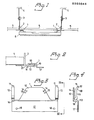
- Fig. 1 schematically illustrates a section through a suspended ceiling structure, where a lighting fixture is carried by inventive fastening devices.
- Fig. 2 illustrates to a larger scale a fastening device in accordance with the invention fixed to a carrying section for a suspended ceiling, the ceiling slabs of which are placed on the horizontal flanges of the carrying sections.
- Fig. 3 is a plan of the fastening device in accordance with the invention.
- Fig. 4 is a side view to a larger scale of the fastening device according to Fig. 3, taken along the line IV-IV in the figure.
- Fig. 1 illustrates a suspended ceiling structure comprising mutually parallel carrying
T sections 2, the horizontal flanges of which carry the edge portions ofceiling slabs 5. Thecarrying sections 2 are suspended in afixed ceiling structure 4 with the aid of verticallyadjustable suspension fittings 3. Alighting fixture 6, the length of which corresponds to the centre-to-centre distance between twoadjacent carrying sections 2, is fixed to them with the aid ofinventive fastening devices 1. - Fig. 2 illustrates
T sections 2 withhorizontal flanges 21, of which one carries afastening device 1 in accordance with the invention, and the other carries aceiling slab 5, on the upper face of its flange. It will be understood that in the embodiment according to Fig. 2 thefastening device 1 may be applied to theflange 21 of a section even when it carries aslab 5. - Turning now to Figs. 3 and 4, it will be seen that the fastening device is formed from a piece of
metal plate 1 having a firstflat edge portion 10, joined by aweb 16 to a secondflat edge portion 17. Theedge portions web 16 is at right angles to them. Theedge portion 10, which forms a flange intended for planar engagement against the upper surface of theflange 21 of thecarrying section 2, is arranged as a central portion of the plate member length. On either side of theflange 10 there is a grippingfinger 11 projecting from theweb 16 substantially in the same direction as theflange 10. A length ofplastic hose 12 is thrust over eachfinger 11. Thefingers 11 depart from the plan of theflange 10 adjacent theweb 16 and theinner part 112 of thefinger 11 extends at an angle of approximately 90° to theflange 10. Theintermediate part 111 of thefinger 11 is substantially parallel to theflange 10. Theoutmost part 110 of the finger is bent out at an angle to theflange 10 to form a cuneiform insertion gap for the clamping fork formed by thefingers 11 andflange 10. - The
flange 10 has punched-out grippingtongues 14, the free ends thereof facing towards theweb 16 to reinforce the grip of the device against theflange 21. - The
flange 10 may have preboredholes 15 for allowing, where necessary, an extra connection of thedevice 1 to thesection 2 with the aid of a joint, such as a pop rivet joint. - The
other end portion 17 of the fastening device, facing away from thefirst edge portion 10, constitutes a fastening tab against which thefixture 6 can be fastened with the aid of a fastening element, such as a screw. Thefixing flange 17 may have prebored holes 18 for facilitating att- achement of thefixture 6 to thetab 17. - It will be understood that for a suspended ceiling structure of the kind illustrated in Figs. 1 and 2, the
fixture 6 can be screwed to thefixing tabs 17 of thefastening devices 1 mounted on the sections with the aid of screws taken through the holes 18 from above and screwed into the horizontal rear portion of thefixture 6. Accessibility for this screwing operation is offered by quite simply lifting out a ceiling slab adjacent to the fixture in the area between theadjacent carrying sections 2. Thefixture 6 often has a length corresponding to the distance between two carryingsections 2, as is illustrated in Fig. 1, whereby the width of the fixture is often considerably less than its length. Thefastening devices 1 can then first be fixed to the fixture 6 (at least one at either end of the fixture) after which thefixture 6 with thedevices 1 is lifted up and placed between the sections. In this operation thefixture 6 is placed parallel to the lower surface of the ceiling so that its longitudinal direction forms an acute angle to the longitudinal direction of the sections, the clamping fork openings of the devices being directed towards the flanges with which they shall engage. By turning the fixture so that its longitudinal direction is at right angles to that of the sections the devices are brought into full engagement with the flanges. - It will be understood that the
fastening devices 1 may thus be attached to thefixtures 6 beforehand with the aid of glue, spot welds, screws, pop rivets or the like. Particularly when screws are utilized, thetab 17 may have prepared holes 18 in the form of elongate slots, which permit adjustment of thedevice 1 on the fixture. - An explicit embodiment of the inventive fastening device has been described above, but it should be quite clear that the embodiment can be modified in many different ways within the scope of the invention. Thus, it may be satisfactory with a single gripping
finger 11 and a flange portion corresponding to theflange 10 on either side of the gripping finger. In certain cases theflange 10 and thetab 17 may be permitted to lie in substantially the same plane, theweb 16 being left out. As an alternative, thetab 16 can extend substantially at a right angle to theplate 10 for connection to an end surface on thefixture 6, e.g. when the end surface is to be contiguous to a wall. Further modifications will be easily understood by one skilled in the art. - Salient advantages of the inventive fastening device are that it can be very easily and quickly fixed to conventional suspended ceiling structures and there also allow rapid and simple fixing of objects such as lighting fixtures to the devices, that the fastening device in accordance with the invention and the fixture can be very easily fitted and removed for possible faults in the fixture, or if the fixture is to be moved, that the fastening device affords a great degree of freedom in respect of the place of suspension for the object on the suspended ceiling, and that the fastening device affords a stable and secure suspension of the object e.g. a lighting fixture.
- As will be seen from Figs. 2, 3 and 4 the
fingers 11 are preferably arranged to extend in the area between the planes of bothedge portions fixture 6 can be brought into planar engagement against thefastening tab 17 without obstruction from thefingers 11. - The
fastening device 1 may be regarded as formed from a piece of plate with two generally parallel edges, which form the free ends of theplates plates plates web 16 together have a generally U-shaped cross section. In all cases, the plates may be regarded as extending away from an imagined central line on the plate, said line being generally parallel to the edges of the plate.
Claims (8)
Priority Applications (1)
| Application Number | Priority Date | Filing Date | Title |
|---|---|---|---|
| AT86850127T ATE67575T1 (en) | 1985-05-23 | 1986-04-14 | DEVICE FOR FIXING AN OBJECT TO A SUSPENDED CEILING. |
Applications Claiming Priority (2)
| Application Number | Priority Date | Filing Date | Title |
|---|---|---|---|
| SE8502565A SE455225B (en) | 1985-05-23 | 1985-05-23 | MOUNTING DEVICE FOR SUSPENSION OF A FORMAL LIKE A LIGHTING LIGHT |
| SE8502565 | 1985-05-23 |
Publications (3)
| Publication Number | Publication Date |
|---|---|
| EP0203045A2 true EP0203045A2 (en) | 1986-11-26 |
| EP0203045A3 EP0203045A3 (en) | 1987-12-23 |
| EP0203045B1 EP0203045B1 (en) | 1991-09-18 |
Family
ID=20360330
Family Applications (1)
| Application Number | Title | Priority Date | Filing Date |
|---|---|---|---|
| EP86850127A Expired - Lifetime EP0203045B1 (en) | 1985-05-23 | 1986-04-14 | Fastening device for carrying an object on a suspended ceiling structure |
Country Status (6)
| Country | Link |
|---|---|
| EP (1) | EP0203045B1 (en) |
| AT (1) | ATE67575T1 (en) |
| DE (1) | DE3681498D1 (en) |
| DK (1) | DK165137C (en) |
| NO (1) | NO169403C (en) |
| SE (1) | SE455225B (en) |
Cited By (2)
| Publication number | Priority date | Publication date | Assignee | Title |
|---|---|---|---|---|
| EP0285575A2 (en) * | 1987-04-02 | 1988-10-05 | Angelo Panzeri | A device for adjustably coupling lighting assemblies to false ceilings, in particular of the type formed by section members and/or panels |
| EP1334246A1 (en) * | 2000-10-27 | 2003-08-13 | Saint-Gobain Ecophon AB | Suspended ceiling and terminal elements therefor |
Citations (5)
| Publication number | Priority date | Publication date | Assignee | Title |
|---|---|---|---|---|
| GB191012609A (en) * | 1910-05-24 | 1910-09-29 | Stanley Bernhard Freiberg | Improvements in Electric Lamp Holders. |
| US3039729A (en) * | 1959-07-24 | 1962-06-19 | Sr Francis E Nagle | Lighting fixture support |
| US3371900A (en) * | 1966-02-14 | 1968-03-05 | Prudential Lighting Corp | Unitary double-detent connector for lighting fixtures |
| US3589660A (en) * | 1970-03-05 | 1971-06-29 | Nat Service Ind Inc | Lighting fixture hanger |
| US4114326A (en) * | 1974-03-28 | 1978-09-19 | Eclipse Mfg. Inc. | Fixture hanging assembly |
-
1985
- 1985-05-23 SE SE8502565A patent/SE455225B/en unknown
-
1986
- 1986-04-14 DE DE8686850127T patent/DE3681498D1/en not_active Expired - Fee Related
- 1986-04-14 AT AT86850127T patent/ATE67575T1/en active
- 1986-04-14 EP EP86850127A patent/EP0203045B1/en not_active Expired - Lifetime
- 1986-05-22 NO NO862048A patent/NO169403C/en unknown
- 1986-05-22 DK DK238586A patent/DK165137C/en not_active IP Right Cessation
Patent Citations (5)
| Publication number | Priority date | Publication date | Assignee | Title |
|---|---|---|---|---|
| GB191012609A (en) * | 1910-05-24 | 1910-09-29 | Stanley Bernhard Freiberg | Improvements in Electric Lamp Holders. |
| US3039729A (en) * | 1959-07-24 | 1962-06-19 | Sr Francis E Nagle | Lighting fixture support |
| US3371900A (en) * | 1966-02-14 | 1968-03-05 | Prudential Lighting Corp | Unitary double-detent connector for lighting fixtures |
| US3589660A (en) * | 1970-03-05 | 1971-06-29 | Nat Service Ind Inc | Lighting fixture hanger |
| US4114326A (en) * | 1974-03-28 | 1978-09-19 | Eclipse Mfg. Inc. | Fixture hanging assembly |
Cited By (3)
| Publication number | Priority date | Publication date | Assignee | Title |
|---|---|---|---|---|
| EP0285575A2 (en) * | 1987-04-02 | 1988-10-05 | Angelo Panzeri | A device for adjustably coupling lighting assemblies to false ceilings, in particular of the type formed by section members and/or panels |
| EP0285575A3 (en) * | 1987-04-02 | 1990-01-24 | Angelo Panzeri | A device for adjustably coupling lighting assemblies to false ceilings, in particular of the type formed by section members and/or panels |
| EP1334246A1 (en) * | 2000-10-27 | 2003-08-13 | Saint-Gobain Ecophon AB | Suspended ceiling and terminal elements therefor |
Also Published As
| Publication number | Publication date |
|---|---|
| NO862048L (en) | 1986-11-24 |
| DK165137C (en) | 1993-03-01 |
| SE8502565L (en) | 1986-11-24 |
| NO169403B (en) | 1992-03-09 |
| DE3681498D1 (en) | 1991-10-24 |
| DK238586D0 (en) | 1986-05-22 |
| EP0203045A3 (en) | 1987-12-23 |
| ATE67575T1 (en) | 1991-10-15 |
| NO169403C (en) | 1992-06-17 |
| SE8502565D0 (en) | 1985-05-23 |
| DK165137B (en) | 1992-10-12 |
| SE455225B (en) | 1988-06-27 |
| DK238586A (en) | 1986-11-24 |
| EP0203045B1 (en) | 1991-09-18 |
Similar Documents
| Publication | Publication Date | Title |
|---|---|---|
| US4757967A (en) | Box support | |
| US3162413A (en) | Bar hanger | |
| US5009383A (en) | Suspended ceiling electrical bracket | |
| US4165851A (en) | Adjustably lockable bar hanger for ceiling boxes and the like | |
| US6761341B2 (en) | Bar hanger and mounting clip assembly | |
| US4408262A (en) | Plaster frame for recessed lighting | |
| US6332597B1 (en) | Mounting bracket and supporting brace | |
| US5484076A (en) | Load bearing mounting bracket for hanging a light fixture from a mounting rail of a grid ceiling system | |
| CA2635382C (en) | Remodeler light fixture support structure and method | |
| US5085393A (en) | Hanger assembly method and apparatus | |
| US5338255A (en) | Air duct fitting mounting shoulder | |
| US20060144009A1 (en) | Metal framing member with off site manufactured locking tabs | |
| US5854443A (en) | Load supporting electrical box suited for attaching to a joist | |
| MXPA96002185A (en) | Adjustable suspens support assembly | |
| US4673235A (en) | Subplate for a low-voltage electric outlet | |
| US5259165A (en) | Supporting metal fittings for double beams | |
| US5295644A (en) | Bracket for mounting an electrical outlet box | |
| EP0203045A2 (en) | Fastening device for carrying an object on a suspended ceiling structure | |
| US20240063620A1 (en) | Electrical Box and Conduit Support Plates | |
| US4015389A (en) | Ceiling system and prefabricated overhead building assembly using this system | |
| EP0774078A1 (en) | Beam fixing device | |
| US4574549A (en) | Adjustable roof insulation system | |
| US6634151B1 (en) | Support apparatus for supporting one or more objects from a concrete structure | |
| US20040182592A1 (en) | Electrical box hanger | |
| JP3051519U (en) | Cover device for cable tray |
Legal Events
| Date | Code | Title | Description |
|---|---|---|---|
| PUAI | Public reference made under article 153(3) epc to a published international application that has entered the european phase |
Free format text: ORIGINAL CODE: 0009012 |
|
| AK | Designated contracting states |
Kind code of ref document: A2 Designated state(s): AT BE CH DE FR GB IT LI LU NL SE |
|
| PUAL | Search report despatched |
Free format text: ORIGINAL CODE: 0009013 |
|
| AK | Designated contracting states |
Kind code of ref document: A3 Designated state(s): AT BE CH DE FR GB IT LI LU NL SE |
|
| 17P | Request for examination filed |
Effective date: 19880617 |
|
| 17Q | First examination report despatched |
Effective date: 19890720 |
|
| GRAA | (expected) grant |
Free format text: ORIGINAL CODE: 0009210 |
|
| RAP1 | Party data changed (applicant data changed or rights of an application transferred) |
Owner name: ECOPHON AKTIEBOLAG |
|
| AK | Designated contracting states |
Kind code of ref document: B1 Designated state(s): AT BE CH DE FR GB IT LI LU NL SE |
|
| PG25 | Lapsed in a contracting state [announced via postgrant information from national office to epo] |
Ref country code: IT Free format text: LAPSE BECAUSE OF FAILURE TO SUBMIT A TRANSLATION OF THE DESCRIPTION OR TO PAY THE FEE WITHIN THE PRE;WARNING: LAPSES OF ITALIAN PATENTS WITH EFFECTIVE DATE BEFORE 2007 MAY HAVE OCCURRED AT ANY TIME BEFORE 2007. THE CORRECT EFFECTIVE DATE MAY BE DIFFERENT FROM THE ONE RECORDED.SCRIBED TIME-LIMIT Effective date: 19910918 Ref country code: AT Effective date: 19910918 Ref country code: LI Effective date: 19910918 Ref country code: NL Effective date: 19910918 Ref country code: CH Effective date: 19910918 Ref country code: BE Effective date: 19910918 |
|
| REF | Corresponds to: |
Ref document number: 67575 Country of ref document: AT Date of ref document: 19911015 Kind code of ref document: T |
|
| REF | Corresponds to: |
Ref document number: 3681498 Country of ref document: DE Date of ref document: 19911024 |
|
| REG | Reference to a national code |
Ref country code: CH Ref legal event code: PL |
|
| EN | Fr: translation not filed | ||
| PG25 | Lapsed in a contracting state [announced via postgrant information from national office to epo] |
Ref country code: FR Effective date: 19920207 |
|
| NLV1 | Nl: lapsed or annulled due to failure to fulfill the requirements of art. 29p and 29m of the patents act | ||
| PG25 | Lapsed in a contracting state [announced via postgrant information from national office to epo] |
Ref country code: GB Effective date: 19920414 |
|
| PG25 | Lapsed in a contracting state [announced via postgrant information from national office to epo] |
Ref country code: LU Free format text: LAPSE BECAUSE OF NON-PAYMENT OF DUE FEES Effective date: 19920430 |
|
| PLBE | No opposition filed within time limit |
Free format text: ORIGINAL CODE: 0009261 |
|
| STAA | Information on the status of an ep patent application or granted ep patent |
Free format text: STATUS: NO OPPOSITION FILED WITHIN TIME LIMIT |
|
| 26N | No opposition filed | ||
| GBPC | Gb: european patent ceased through non-payment of renewal fee | ||
| PG25 | Lapsed in a contracting state [announced via postgrant information from national office to epo] |
Ref country code: DE Effective date: 19930101 |
|
| REG | Reference to a national code |
Ref country code: FR Ref legal event code: ST |
|
| EAL | Se: european patent in force in sweden |
Ref document number: 86850127.1 |
|
| PGFP | Annual fee paid to national office [announced via postgrant information from national office to epo] |
Ref country code: SE Payment date: 19990225 Year of fee payment: 14 |
|
| PG25 | Lapsed in a contracting state [announced via postgrant information from national office to epo] |
Ref country code: SE Free format text: LAPSE BECAUSE OF NON-PAYMENT OF DUE FEES Effective date: 20000415 |
|
| EUG | Se: european patent has lapsed |
Ref document number: 86850127.1 |