US5259165A - Supporting metal fittings for double beams - Google Patents
Supporting metal fittings for double beams Download PDFInfo
- Publication number
- US5259165A US5259165A US07/927,843 US92784392A US5259165A US 5259165 A US5259165 A US 5259165A US 92784392 A US92784392 A US 92784392A US 5259165 A US5259165 A US 5259165A
- Authority
- US
- United States
- Prior art keywords
- beams
- sides
- metal fitting
- gap
- portions
- Prior art date
- Legal status (The legal status is an assumption and is not a legal conclusion. Google has not performed a legal analysis and makes no representation as to the accuracy of the status listed.)
- Expired - Lifetime
Links
- 239000002184 metal Substances 0.000 title claims abstract description 73
- 229910052751 metal Inorganic materials 0.000 title claims abstract description 73
- 230000000717 retained effect Effects 0.000 claims abstract description 3
- 238000004519 manufacturing process Methods 0.000 abstract description 4
- XEEYBQQBJWHFJM-UHFFFAOYSA-N Iron Chemical compound [Fe] XEEYBQQBJWHFJM-UHFFFAOYSA-N 0.000 description 6
- 229910052742 iron Inorganic materials 0.000 description 3
- 238000003466 welding Methods 0.000 description 3
- 238000005452 bending Methods 0.000 description 1
- 238000005520 cutting process Methods 0.000 description 1
- 238000003754 machining Methods 0.000 description 1
- 238000012423 maintenance Methods 0.000 description 1
- 239000000463 material Substances 0.000 description 1
- 235000012054 meals Nutrition 0.000 description 1
- 238000000034 method Methods 0.000 description 1
- 125000006850 spacer group Chemical group 0.000 description 1
- 239000002699 waste material Substances 0.000 description 1
Images


Classifications
-
- E—FIXED CONSTRUCTIONS
- E04—BUILDING
- E04C—STRUCTURAL ELEMENTS; BUILDING MATERIALS
- E04C3/00—Structural elongated elements designed for load-supporting
- E04C3/02—Joists; Girders, trusses, or trusslike structures, e.g. prefabricated; Lintels; Transoms; Braces
- E04C3/04—Joists; Girders, trusses, or trusslike structures, e.g. prefabricated; Lintels; Transoms; Braces of metal
- E04C3/06—Joists; Girders, trusses, or trusslike structures, e.g. prefabricated; Lintels; Transoms; Braces of metal with substantially solid, i.e. unapertured, web
-
- E—FIXED CONSTRUCTIONS
- E04—BUILDING
- E04C—STRUCTURAL ELEMENTS; BUILDING MATERIALS
- E04C3/00—Structural elongated elements designed for load-supporting
- E04C3/02—Joists; Girders, trusses, or trusslike structures, e.g. prefabricated; Lintels; Transoms; Braces
- E04C3/04—Joists; Girders, trusses, or trusslike structures, e.g. prefabricated; Lintels; Transoms; Braces of metal
- E04C2003/0404—Joists; Girders, trusses, or trusslike structures, e.g. prefabricated; Lintels; Transoms; Braces of metal beams, girders, or joists characterised by cross-sectional aspects
- E04C2003/0408—Joists; Girders, trusses, or trusslike structures, e.g. prefabricated; Lintels; Transoms; Braces of metal beams, girders, or joists characterised by cross-sectional aspects characterised by assembly or the cross-section
- E04C2003/0413—Joists; Girders, trusses, or trusslike structures, e.g. prefabricated; Lintels; Transoms; Braces of metal beams, girders, or joists characterised by cross-sectional aspects characterised by assembly or the cross-section being built up from several parts
- E04C2003/0417—Joists; Girders, trusses, or trusslike structures, e.g. prefabricated; Lintels; Transoms; Braces of metal beams, girders, or joists characterised by cross-sectional aspects characterised by assembly or the cross-section being built up from several parts demountable
-
- E—FIXED CONSTRUCTIONS
- E04—BUILDING
- E04C—STRUCTURAL ELEMENTS; BUILDING MATERIALS
- E04C3/00—Structural elongated elements designed for load-supporting
- E04C3/02—Joists; Girders, trusses, or trusslike structures, e.g. prefabricated; Lintels; Transoms; Braces
- E04C3/04—Joists; Girders, trusses, or trusslike structures, e.g. prefabricated; Lintels; Transoms; Braces of metal
- E04C2003/0404—Joists; Girders, trusses, or trusslike structures, e.g. prefabricated; Lintels; Transoms; Braces of metal beams, girders, or joists characterised by cross-sectional aspects
- E04C2003/0426—Joists; Girders, trusses, or trusslike structures, e.g. prefabricated; Lintels; Transoms; Braces of metal beams, girders, or joists characterised by cross-sectional aspects characterised by material distribution in cross section
- E04C2003/0434—Joists; Girders, trusses, or trusslike structures, e.g. prefabricated; Lintels; Transoms; Braces of metal beams, girders, or joists characterised by cross-sectional aspects characterised by material distribution in cross section the open cross-section free of enclosed cavities
-
- E—FIXED CONSTRUCTIONS
- E04—BUILDING
- E04C—STRUCTURAL ELEMENTS; BUILDING MATERIALS
- E04C3/00—Structural elongated elements designed for load-supporting
- E04C3/02—Joists; Girders, trusses, or trusslike structures, e.g. prefabricated; Lintels; Transoms; Braces
- E04C3/04—Joists; Girders, trusses, or trusslike structures, e.g. prefabricated; Lintels; Transoms; Braces of metal
- E04C2003/0404—Joists; Girders, trusses, or trusslike structures, e.g. prefabricated; Lintels; Transoms; Braces of metal beams, girders, or joists characterised by cross-sectional aspects
- E04C2003/0443—Joists; Girders, trusses, or trusslike structures, e.g. prefabricated; Lintels; Transoms; Braces of metal beams, girders, or joists characterised by cross-sectional aspects characterised by substantial shape of the cross-section
- E04C2003/046—L- or T-shaped
-
- Y—GENERAL TAGGING OF NEW TECHNOLOGICAL DEVELOPMENTS; GENERAL TAGGING OF CROSS-SECTIONAL TECHNOLOGIES SPANNING OVER SEVERAL SECTIONS OF THE IPC; TECHNICAL SUBJECTS COVERED BY FORMER USPC CROSS-REFERENCE ART COLLECTIONS [XRACs] AND DIGESTS
- Y10—TECHNICAL SUBJECTS COVERED BY FORMER USPC
- Y10T—TECHNICAL SUBJECTS COVERED BY FORMER US CLASSIFICATION
- Y10T403/00—Joints and connections
- Y10T403/71—Rod side to plate or side
- Y10T403/7117—Flanged or grooved rod
-
- Y—GENERAL TAGGING OF NEW TECHNOLOGICAL DEVELOPMENTS; GENERAL TAGGING OF CROSS-SECTIONAL TECHNOLOGIES SPANNING OVER SEVERAL SECTIONS OF THE IPC; TECHNICAL SUBJECTS COVERED BY FORMER USPC CROSS-REFERENCE ART COLLECTIONS [XRACs] AND DIGESTS
- Y10—TECHNICAL SUBJECTS COVERED BY FORMER USPC
- Y10T—TECHNICAL SUBJECTS COVERED BY FORMER US CLASSIFICATION
- Y10T403/00—Joints and connections
- Y10T403/71—Rod side to plate or side
- Y10T403/7123—Traversed by connector
Definitions
- the present invention relates to a supporting metal fitting for use in installing ducts, pipes, instruments, air conditioners, etc. on a ceiling of a building and the like.
- the conventional double beam arrangement comprises two L-type beams (L-beams), each having first and second sides extending in an angled relationship to each other as illustrated in FIGS. 1 and 2.
- the L-beams or as generically referred to hereinafter, double beams a, are disposed in a back to back spaced apart relationship with a gap c provided therebetween so that a lifting metal fitting b can be inserted into the gap c.
- the gap c is defined, as illustrated in FIG. 1, by welding a spacer d formed of a round rod to the angles a at a given interval therebetween.
- the gap c is also defined by interposing a collar e between the angles a and inserting a bolt f into the angles a and the collar e so as to fasten them by a nut g.
- the supporting metal fittings for double beams which are each composed of first and second sides are provided.
- the first sides are disposed in parallel in a back to back relationship with each other and spaced away from each other at a given interval.
- An upper metal fitting having notched portions in which the upper portions of the double beams are engaged and a tongue portion which engages in a gap between the double beams, a lower metal fitting having retainers by which the lower portions of the double beams is retained and a tongue portion which engages in the gap between the double beams, and a fixing member coupled to both the upper and lower metal fittings and inserted into the gap between the double beams for fixing them together.
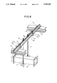
- FIG. 1 is a perspective view showing conventional double beams
- FIG. 2 is a perspective view showing another conventional double beams
- FIG. 3 is a plan view showing supporting metal fittings for double beams according to a first embodiment of the present invention
- FIG. 4 is a front view of the supporting metal fittings for double beams in FIG. 3;
- FIG. 5 is a side view of the supporting metal fittings for double beams in FIG. 3;
- FIG. 6 is a view showing a first example of using the supporting metal fittings for double beams in FIG. 3;
- FIG. 7 is a view showing a second example of using the supporting metal fittings for double beams in FIG. 3;
- FIG. 8 is a side view of supporting metal fittings for double beams according to a second embodiment of the present invention.
- FIG. 9 is a plan view showing the supporting metal fittings for double beams according to the second embodiment of the present invention.
- FIG. 10 is a front view of the supporting metal fittings for double beams in FIG. 9.
- FIG. 11 is a side view of the supporting metal fittings for double beams in FIG. 9.
- FIGS. 3 to 7 illustrate supporting metal fittings employing double beams having two sides.
- Each of the supporting metal fittings 1 comprises an upper metal fitting 2 and a lower metal fitting 3 respectively formed by bending a metal plate.
- the upper supporting metal fitting 2 has a substantially U-shape in cross section and has an opening which is directed downward.
- the upper supporting metal fitting 2 comprises side plates 2a and 2b and an upper plate 2c.
- the side plate 2a has notched portions 2d in which upper ends of a pair of beams 4, which are disposed back to back, are engaged at a given interval defining a gap 5 therebetween.
- the side plate 2a has a circular arc shaped tongue portion 3e protruding therefrom between the notched portions 2d so as to facilitate the upper ends of the beams 4 into the notched portions 2d as illustrated in FIG. 4.
- Another side plate 2b of the upper metal fitting 2 has a narrow vertical width and has a tongue portion 2f which is the same as the tongue portion 2e of the side plate 2a at the location and the shape thereof.
- the upper plate 2c has a length which is substantially the same as the length of the side plate 2b but slightly shorter than the length of the side plate 2a.
- the upper plate 2c has a small hole 2g at the central portion thereof through which the fixing member 6 such as a bolt can be inserted.
- the lower metal fitting 3 of the supporting metal fitting body 1 has a substantially U-shape in cross section and has an opening which is directed upward.
- the lower metal fitting 3 has side plates 3a and 3b and a lower plate 3c in which the side plates 3a and 3b are longer than the side plates 2a and 2b of the upper metal fitting 2.
- the side plate 3a has a length longer than the width of the lower portion of the double beams 4 which are composed of two angles spaced away from each other at a given interval.
- the side plate 3a has hooked retainers 3d at both sides thereof and a tongue portion 3e protruding upward from the central portion thereof for receiving the tip ends of the lower portion of the double beams 4 therebetween to engage them as illustrated in FIG. 4.
- the tongue 3e projects upward at the central portion of the side plate 3a between the retainers 3d to engage into the space between the double beams 4 from the lower portion of the space to thereby hold the double beams 4 at a given interval.
- the tip end of the tongue portion 3e arches like tongue portions 2e and 2f of the upper metal fitting 2.
- Another side plate 3b of the lower metal fitting 3 has substantially the same length as that of the side plate 2a of the upper metal fitting 2.
- the side plate 3b has a tongue portion 3f which protrudes upward from the central portion thereof and has a shape same as the side plate 3a.
- the lower plate 3c has a substantially a shape of trapezoid so as to connect to the long side plate 3a to the short side plate 3b and has a screw hole 3g which penetrates the central portion thereof and into which a fixing member 6 is screwed.
- FIG. 6 shows the case where the duct 8 is suspended and installed and
- FIG. 7 shows the case where the air conditioner 9 is suspended and installed using lifting metal fittings 7.
- the angles are cut to be fit to a span between iron beams 10 and be capable of being placed on the iron beams 10 and disposed back to back and parallel with each other so as to form the double beams 4.
- the upper metal fittings 2 are attached to the upper portion of the double beams 4 at arbitrary intervals in the longitudinal direction of the double beams 4.
- the lower metal fittings 3 are attached to the lower portion of the double beams 4 in the same manner as the upper metal fittings 2.
- the upper metal fitting 2 is attached to the double beams 4 in the manner that the upper portions of the double beams 4 are inserted into the notched portions 2d of the side plates 2a and the tongue portions 2e and 2f of the side plates 2a and 2b are inserted downward into the gap defined between the double beams 4 as illustrated in FIGS. 3 to 5.
- the lower metal fitting 3 is attached to the double beams 4 in the manner that the lower portions of the double beams 4 are lowered so that the lower sides of the double beams are positioned on the upper surface of the side plate 3a of the lower metal fitting 3 whereby the tip ends of the lower portions of the double beams 4 are engaged with the retainers 3d of the lower metal fitting 3a, as illustrated in FIG. 4 and at the same time, the tongue portions 3e and 3f of the side plates 3a and 3b are inserted into the gap between the double beams 4.
- the fixing member 6 having a washer 6a at the head portion thereof and a threaded portion at the lower portion thereof, is inserted into the gap between the double beams 4 from the small hole 2g of the upper metal fitting 2 and the lower portion thereof is screwed into the screw hole 3g of the lower metal fitting 3 to fasten the fixing member 6.
- both ends of the double beams are fixed to the iron beams 10 of the building by welding, etc.
- the duct 8 and the air conditioner 9 are installed as follows.
- the upper ends of the lifting metal fittings 7 are inserted into the gap between the double beams and nuts 7b are screwed onto the upper threaded portions of the lifting metal fittings 7 by way of washers 7a whereby the upper portions of the lifting metal fittings 7 can be attached to the double beams 4.
- the duct 8 and the air conditioner 9 can be suspended at the lower portions of the lifting metal fittings 7 in the conventional manner. A sufficient strength can be obtained by the double beams for a heavy hanging load since the supporting metal fittings 1 keep the gap between the double beams 4 constant.
- the fixing member 6 is screwed into the screw hole 3g defined on the lower metal fitting 3.
- the lower metal fitting 3 may have a small hole 3h therein through which the fixing member 6 is inserted and fixed by a nut 6b by way of a washer 6a as illustrated in FIG. 8.
- the supporting meal fittings according to the second embodiment can accommodate double beams 4 each comprising a third side substantially parallel to the second side and rigidly secured to an adjacent end of the first side (C-shaped beams).
- the notched portions of the upper metal fitting 3a are engaged with, and securely retain the third sides of the double beams as illustrated in FIGS. 9 to 11.
- the double beams can be manufactured with ease at the building site to cope with an arbitrary hanging load, it is not necessary to previously manufacture and keep a plurality of double beams at a factor so that it is possible to reduce the space and labor for keeping the same, which results in a remarkable cost reduction.
Landscapes
- Engineering & Computer Science (AREA)
- Architecture (AREA)
- Civil Engineering (AREA)
- Structural Engineering (AREA)
- Supports For Pipes And Cables (AREA)
- Duct Arrangements (AREA)
Abstract
Supporting metal fittings for double beams comprising, double beams which are composed of two angles disposed in parallel with each other at a given interval, an upper metal fitting having notched portions in which the upper portions of the double beams are engaged, said upper metal fitting also having a tongue portion which engages between the double beams, a lower metal fitting having retainers by which the lower portion of the double beams is retained, said lower metal fitting also having a tongue portion which engages between the double beams, and a fixing member coupled to both the upper and lower metal fittings and inserted between the double beams for fixing them together, enabling the easy manufacturing of the supporting metal fittings for double beams for installing ducts, etc., using non-machined angles.
Description
1. Field of the Invention:
The present invention relates to a supporting metal fitting for use in installing ducts, pipes, instruments, air conditioners, etc. on a ceiling of a building and the like.
2. Prior Art:
Conventionally, when ducts, pipes, instruments air conditioners, etc. are installed inside a building, there is employed a method comprising the steps of previously preparing a double beam arrangement for use on a portion adjacent to the ceiling of the building, mounting metal fittings on the double beam arrangement and suspending such ducts, etc. by the metal fittings mounted on the double beam arrangement.
The conventional double beam arrangement comprises two L-type beams (L-beams), each having first and second sides extending in an angled relationship to each other as illustrated in FIGS. 1 and 2.
In the double beam arrangement the L-beams, or as generically referred to hereinafter, double beams a, are disposed in a back to back spaced apart relationship with a gap c provided therebetween so that a lifting metal fitting b can be inserted into the gap c. The gap c is defined, as illustrated in FIG. 1, by welding a spacer d formed of a round rod to the angles a at a given interval therebetween. The gap c is also defined by interposing a collar e between the angles a and inserting a bolt f into the angles a and the collar e so as to fasten them by a nut g.
However, since it takes time and labor for providing the gap by welding or fastening by the bolt and the nut, and various sizes of the angles should be manufactured depending on a hanging load, there is such a drawback that the custody and the maintenance of the angles are troublesome.
If they were cut to a necessary length at a building site, remaining portions of angles after cutting can not be used for other purposes, which renders the angles to be wasteful.
It is an object of the present invention to improve the drawbacks of the conventional supporting metal fittings and to provide supporting metal fittings for L-beams capable of forming a double beam arrangement without machining the L-beams.
To achieve the object, the supporting metal fittings for double beams which are each composed of first and second sides are provided. The first sides are disposed in parallel in a back to back relationship with each other and spaced away from each other at a given interval. An upper metal fitting having notched portions in which the upper portions of the double beams are engaged and a tongue portion which engages in a gap between the double beams, a lower metal fitting having retainers by which the lower portions of the double beams is retained and a tongue portion which engages in the gap between the double beams, and a fixing member coupled to both the upper and lower metal fittings and inserted into the gap between the double beams for fixing them together.
With the arrangement set forth above, it is possible to manufacture the double beams capable of suspending the ducts, pipes, air conditioners, etc. with ease even at a building site.
FIG. 1 is a perspective view showing conventional double beams;
FIG. 2 is a perspective view showing another conventional double beams;
FIG. 3 is a plan view showing supporting metal fittings for double beams according to a first embodiment of the present invention;
FIG. 4 is a front view of the supporting metal fittings for double beams in FIG. 3;
FIG. 5 is a side view of the supporting metal fittings for double beams in FIG. 3;
FIG. 6 is a view showing a first example of using the supporting metal fittings for double beams in FIG. 3;
FIG. 7 is a view showing a second example of using the supporting metal fittings for double beams in FIG. 3;
FIG. 8 is a side view of supporting metal fittings for double beams according to a second embodiment of the present invention;
FIG. 9 is a plan view showing the supporting metal fittings for double beams according to the second embodiment of the present invention;
FIG. 10 is a front view of the supporting metal fittings for double beams in FIG. 9; and
FIG. 11 is a side view of the supporting metal fittings for double beams in FIG. 9.
First Embodiment (FIGS. 3 to 7):
Supporting metal fittings for double beams according to the first embodiment of the present invention will be described with references to FIGS. 3 to 7.
FIGS. 3 to 7 illustrate supporting metal fittings employing double beams having two sides.
Each of the supporting metal fittings 1 comprises an upper metal fitting 2 and a lower metal fitting 3 respectively formed by bending a metal plate.
The upper supporting metal fitting 2 has a substantially U-shape in cross section and has an opening which is directed downward. The upper supporting metal fitting 2 comprises side plates 2a and 2b and an upper plate 2c. The side plate 2a has notched portions 2d in which upper ends of a pair of beams 4, which are disposed back to back, are engaged at a given interval defining a gap 5 therebetween. The side plate 2a has a circular arc shaped tongue portion 3e protruding therefrom between the notched portions 2d so as to facilitate the upper ends of the beams 4 into the notched portions 2d as illustrated in FIG. 4. Another side plate 2b of the upper metal fitting 2 has a narrow vertical width and has a tongue portion 2f which is the same as the tongue portion 2e of the side plate 2a at the location and the shape thereof. The upper plate 2c has a length which is substantially the same as the length of the side plate 2b but slightly shorter than the length of the side plate 2a. The upper plate 2c has a small hole 2g at the central portion thereof through which the fixing member 6 such as a bolt can be inserted.
The lower metal fitting 3 of the supporting metal fitting body 1 has a substantially U-shape in cross section and has an opening which is directed upward. The lower metal fitting 3 has side plates 3a and 3b and a lower plate 3c in which the side plates 3a and 3b are longer than the side plates 2a and 2b of the upper metal fitting 2.
The side plate 3a has a length longer than the width of the lower portion of the double beams 4 which are composed of two angles spaced away from each other at a given interval. The side plate 3a has hooked retainers 3d at both sides thereof and a tongue portion 3e protruding upward from the central portion thereof for receiving the tip ends of the lower portion of the double beams 4 therebetween to engage them as illustrated in FIG. 4. The tongue 3e projects upward at the central portion of the side plate 3a between the retainers 3d to engage into the space between the double beams 4 from the lower portion of the space to thereby hold the double beams 4 at a given interval. The tip end of the tongue portion 3e arches like tongue portions 2e and 2f of the upper metal fitting 2. Another side plate 3b of the lower metal fitting 3 has substantially the same length as that of the side plate 2a of the upper metal fitting 2. The side plate 3b has a tongue portion 3f which protrudes upward from the central portion thereof and has a shape same as the side plate 3a. The lower plate 3c has a substantially a shape of trapezoid so as to connect to the long side plate 3a to the short side plate 3b and has a screw hole 3g which penetrates the central portion thereof and into which a fixing member 6 is screwed.
An operation of the supporting metal fittings will be described with reference to FIGS. 6 and 7.
FIG. 6 shows the case where the duct 8 is suspended and installed and FIG. 7 shows the case where the air conditioner 9 is suspended and installed using lifting metal fittings 7.
In either case, the angles are cut to be fit to a span between iron beams 10 and be capable of being placed on the iron beams 10 and disposed back to back and parallel with each other so as to form the double beams 4. The upper metal fittings 2 are attached to the upper portion of the double beams 4 at arbitrary intervals in the longitudinal direction of the double beams 4. The lower metal fittings 3 are attached to the lower portion of the double beams 4 in the same manner as the upper metal fittings 2.
The upper metal fitting 2 is attached to the double beams 4 in the manner that the upper portions of the double beams 4 are inserted into the notched portions 2d of the side plates 2a and the tongue portions 2e and 2f of the side plates 2a and 2b are inserted downward into the gap defined between the double beams 4 as illustrated in FIGS. 3 to 5.
The lower metal fitting 3 is attached to the double beams 4 in the manner that the lower portions of the double beams 4 are lowered so that the lower sides of the double beams are positioned on the upper surface of the side plate 3a of the lower metal fitting 3 whereby the tip ends of the lower portions of the double beams 4 are engaged with the retainers 3d of the lower metal fitting 3a, as illustrated in FIG. 4 and at the same time, the tongue portions 3e and 3f of the side plates 3a and 3b are inserted into the gap between the double beams 4.
At the state where the upper and lower metal fittings 2 and 3 are attached to the double beams 4, the fixing member 6, having a washer 6a at the head portion thereof and a threaded portion at the lower portion thereof, is inserted into the gap between the double beams 4 from the small hole 2g of the upper metal fitting 2 and the lower portion thereof is screwed into the screw hole 3g of the lower metal fitting 3 to fasten the fixing member 6.
Upon completion of the attachment of the necessary numbers of supporting metal fittings 1 to the double beams arranged in the longitudinal direction of the double beams, both ends of the double beams are fixed to the iron beams 10 of the building by welding, etc.
The duct 8 and the air conditioner 9 are installed as follows. The upper ends of the lifting metal fittings 7 are inserted into the gap between the double beams and nuts 7b are screwed onto the upper threaded portions of the lifting metal fittings 7 by way of washers 7a whereby the upper portions of the lifting metal fittings 7 can be attached to the double beams 4. The duct 8 and the air conditioner 9 can be suspended at the lower portions of the lifting metal fittings 7 in the conventional manner. A sufficient strength can be obtained by the double beams for a heavy hanging load since the supporting metal fittings 1 keep the gap between the double beams 4 constant.
Second Embodiment (FIGS. 8 to 11)
Supporting metal fittings for double beams according to a second embodiment will be described with reference to FIGS. 8 to 11.
According to the first embodiment, the fixing member 6 is screwed into the screw hole 3g defined on the lower metal fitting 3. However, the lower metal fitting 3 may have a small hole 3h therein through which the fixing member 6 is inserted and fixed by a nut 6b by way of a washer 6a as illustrated in FIG. 8.
Although the double beams 4 according to the first embodiment comprise two sides, the supporting meal fittings according to the second embodiment can accommodate double beams 4 each comprising a third side substantially parallel to the second side and rigidly secured to an adjacent end of the first side (C-shaped beams). In the second embodiment, the notched portions of the upper metal fitting 3a are engaged with, and securely retain the third sides of the double beams as illustrated in FIGS. 9 to 11.
It is possible to remarkably reduce the time and labor involved in the manufacturing the double beams for suspending the ducts, pipes, air conditioners, etc. from the ceiling of a building compared with conventional double beams which have been manufactured using angles or channels machined at the factory.
Furthermore, since the double beams can be manufactured with ease at the building site to cope with an arbitrary hanging load, it is not necessary to previously manufacture and keep a plurality of double beams at a factor so that it is possible to reduce the space and labor for keeping the same, which results in a remarkable cost reduction.
Furthermore, inasmuch as non-machined beams are cut to a necessary length at the building site, remaining portions can be used for other purposes, so as to eliminate a waste of materials.
Claims (13)
1. A fitting device for rigidly connecting first and second beams in a back-to-back spaced apart arrangement which defines a gap therebetween, each said beam having a first side which defines one boundary of said gap extends at an angle of approximately 90 degrees away from a second side, said first and second sides of each beam being rigidly joined at adjacent ends thereof with said second sides projecting outwardly in opposite directions away from said gap, said device comprising:
a downwardly facing, substantially U-shaped, upper member including a central top plate having substantially parallel first and second end plates substantially perpendicularly secured to opposite ends thereof, said central top plate having a bore therethrough, said first end plate having two sidewardly spaced first notches which cooperate to define a first tongue part downwardly projecting therebetween, said first notches receiving therein upper ends of the first sides of the first and second beams respectively, and said first tongue part disposed within the gap, said second end plate also having a downwardly projecting second tongue part disposed within the gap;
an upwardly facing, substantially U-shaped lower member including a central bottom plate having substantially parallel first and second end plates substantially perpendicularly secured to opposite ends thereof, said central bottom plate having a bore therethrough, said first end plate having tow sidewardly spaced second notches which cooperate to define a third tongue part upwardly projecting therebetween, said second notches receiving therein the second sides of the first and second beams respectively, and said third tongue part disposed within the gap, said second end plate also having an upwardly projecting fourth tongue part disposed within the gap; and
a fixing means for extending between and rigidly securing said upper and lower members together in fixed securement to the first and second beams.
2. The device as claimed in claim 1, wherein said central top and central bottom plates are substantially trapezoidal in shape and each has a wide end and a narrow end, said first end plate of the upper member and said first end plate of the lower member being secured to the wide ends of the central top and central bottom plates, respectively, and said second end plate of the upper member and said second end plate of the lower member being secured to the narrow ends of the central top and central bottom plates, respectively.
3. The device as claimed in claim 1, wherein said fixing means is a bolt disposed within the gap and passing through the bores in the central top and bottom plates, said bolt also serving to support an object suspended therefrom.
4. The device as claimed in claim 3 wherein said object is a duct.
5. The device as claimed in claim 3 wherein said object is a pipe.
6. The device as claimed in claim 3 wherein said object is a support platform for supporting an air conditioner, or the like.
7. The device as claimed in claim 1, wherein said first, second, third, and fourth tongue parts have substantially equal dimensions for substantially maintaining a desired gap dimension along the longitudinal axis of the first and second beams.
8. The device as claimed in claim 1, wherein said first end plate of the lower member includes first and second retaining portions secured to upward portions of the second notches, respectively for engaging an upper surface of each second side of the first and second beams, respectively.
9. The device as claimed in claim 1 wherein each said first and second beams further comprise a third side substantially parallel to the second side and rigidly joined to the first side at adjacent ends thereof so that each beam is of a generally C-shape, and said first notches receive therein the third sides of the first and second beams, respectively.
10. The device as claimed in claim 9, wherein said first end plate of the upper member includes first and second retaining portions secured to downward portions of the first notches, respectively for engaging a lower surface of each third side of the first and second beams, respectively.
11. A supporting metal fitting for a double beam arrangement wherein each of two beams include first and second sides extending in an angled relationship, said beams being disposed with the first sides in a back-to-back spaced apart relationship, said supporting metal fitting comprising:
a one-piece upper metal fitting having sidewardly-spaced first notched portions in which upper portions of the first sides of the two beams are engaged, said upper metal fitting also having a first tongue portion which engages between the first sides of the two beams;
a one-piece lower metal fitting having sidewardly-spaced second notched portions in which the second sides of the two beams are retained, said lower metal fitting also having a second tongue portion positioned between the second notched portions for engagement between the two beams; and
a fixing member positioned between the first sides and coupled to both the upper and lower metal fittings for fixing them together.
12. The device as claimed in claim 11 wherein each said first and second beams further comprise a third side substantially parallel to the second side and rigidly joined to the first side at adjacent ends thereof so that each beam is of a generally C-shape, and said first notched portions receive therein the third sides of the first and second beams, respectively.
13. The device as claimed in claim 12, wherein said upper metal fitting includes first and second retaining portions secured to downward portions of the first notched portions, respectively for engaging a lower surface of each third side of the first and second beams, respectively.
Priority Applications (1)
| Application Number | Priority Date | Filing Date | Title |
|---|---|---|---|
| US07/927,843 US5259165A (en) | 1992-08-10 | 1992-08-10 | Supporting metal fittings for double beams |
Applications Claiming Priority (1)
| Application Number | Priority Date | Filing Date | Title |
|---|---|---|---|
| US07/927,843 US5259165A (en) | 1992-08-10 | 1992-08-10 | Supporting metal fittings for double beams |
Publications (1)
| Publication Number | Publication Date |
|---|---|
| US5259165A true US5259165A (en) | 1993-11-09 |
Family
ID=25455346
Family Applications (1)
| Application Number | Title | Priority Date | Filing Date |
|---|---|---|---|
| US07/927,843 Expired - Lifetime US5259165A (en) | 1992-08-10 | 1992-08-10 | Supporting metal fittings for double beams |
Country Status (1)
| Country | Link |
|---|---|
| US (1) | US5259165A (en) |
Cited By (16)
| Publication number | Priority date | Publication date | Assignee | Title |
|---|---|---|---|---|
| US5855095A (en) * | 1997-05-06 | 1999-01-05 | General Motors Corporation | Boltless glass channel attachment |
| US6485219B1 (en) * | 2000-11-20 | 2002-11-26 | Haworth, Inc. | Ganging bracket for a shelf unit |
| US6547482B2 (en) * | 1999-12-15 | 2003-04-15 | Peri Gmbh | Hook strap |
| US6749359B1 (en) * | 2001-04-27 | 2004-06-15 | Automated Fire Control, Incorporated | Seismic suspension system |
| US20050056757A1 (en) * | 2003-08-15 | 2005-03-17 | Hartwick Sam K. | Industrial hanger for metal framing |
| US20060076803A1 (en) * | 2004-10-08 | 2006-04-13 | Wilhelm Kreutzberg | Arrangement for connecting two elements |
| DE102006016952A1 (en) * | 2006-04-11 | 2007-10-25 | Volkswagen Ag | Connecting device, especially for container for fixing different components, has profiled support formed from at least two profile elements with L-shaped basic form which are interconnected so that space exists between profile elements |
| US20070266674A1 (en) * | 2006-05-19 | 2007-11-22 | Morey Douglas H | Clamp for use with metal bar joists and beams |
| WO2008086468A3 (en) * | 2007-01-10 | 2008-12-04 | Douglas H Morey | Adjustable hanger assembly for use with metal bar joists and beams |
| US20100176634A1 (en) * | 2009-01-14 | 2010-07-15 | Kimball International, Inc. | Connecting arrangement for articles of furniture |
| US7819371B2 (en) | 2007-07-02 | 2010-10-26 | Illinois Tool Works Inc. | Universal suspended anchor system |
| US20100282920A1 (en) * | 2008-05-22 | 2010-11-11 | Mcpheeters Greg | Universal end clamp |
| US20120181396A1 (en) * | 2011-01-19 | 2012-07-19 | Conxtech, Inc. | Modular pipe-shoe, pipe-support system |
| US9255402B2 (en) * | 2014-04-25 | 2016-02-09 | Worthington Armstrong Venture | Hanging load support |
| US11445844B2 (en) * | 2020-07-16 | 2022-09-20 | Claus Peter Rodenbostel | Prosthetic locking liner drying hook |
| JP2023111373A (en) * | 2022-01-31 | 2023-08-10 | Emfort株式会社 | Suspension mount |
Citations (15)
| Publication number | Priority date | Publication date | Assignee | Title |
|---|---|---|---|---|
| US1854241A (en) * | 1925-06-19 | 1932-04-19 | Walter A Adams | Means for fastening boards or pieces to supports |
| US1893481A (en) * | 1925-06-19 | 1933-01-10 | Walter A Adams | Table, bench, shelf, or similar structures |
| FR978964A (en) * | 1942-12-29 | 1951-04-20 | Fast construction of square element scaffolding | |
| US2570169A (en) * | 1945-09-15 | 1951-10-02 | Adlake Co | Sash construction |
| GB667090A (en) * | 1950-01-28 | 1952-02-27 | Lindsay Ltd Henry | Improvements in or relating to clips for securing articles |
| US2686699A (en) * | 1953-04-16 | 1954-08-17 | Kaiser Metal Products Inc | Joint for connecting sink tops |
| US2926350A (en) * | 1957-02-28 | 1960-02-23 | Sr Francis K Saul | Collapsible antenna |
| US3363382A (en) * | 1965-09-03 | 1968-01-16 | Dow Chemical Co | Meshing panels with interfitting expandable locking strips |
| US3590542A (en) * | 1970-01-21 | 1971-07-06 | Prestressed Concrete Of Colora | Connection system for concrete and steel structures |
| US4021991A (en) * | 1975-02-21 | 1977-05-10 | Hotz Roger W | Fastening device |
| US4350318A (en) * | 1981-01-15 | 1982-09-21 | Harsco Corporation | Tie plate |
| US4409906A (en) * | 1981-03-31 | 1983-10-18 | Alneng Carl Goeran | Clamping device for joining boards |
| US4798029A (en) * | 1987-11-30 | 1989-01-17 | Fibergrate Corporation | Hold-down clamp |
| US4802422A (en) * | 1986-05-06 | 1989-02-07 | Herman Miller, Inc. | Work surface ganging clip |
| US5020678A (en) * | 1989-06-27 | 1991-06-04 | Unarco Industries, Inc. | Structural rack |
-
1992
- 1992-08-10 US US07/927,843 patent/US5259165A/en not_active Expired - Lifetime
Patent Citations (15)
| Publication number | Priority date | Publication date | Assignee | Title |
|---|---|---|---|---|
| US1854241A (en) * | 1925-06-19 | 1932-04-19 | Walter A Adams | Means for fastening boards or pieces to supports |
| US1893481A (en) * | 1925-06-19 | 1933-01-10 | Walter A Adams | Table, bench, shelf, or similar structures |
| FR978964A (en) * | 1942-12-29 | 1951-04-20 | Fast construction of square element scaffolding | |
| US2570169A (en) * | 1945-09-15 | 1951-10-02 | Adlake Co | Sash construction |
| GB667090A (en) * | 1950-01-28 | 1952-02-27 | Lindsay Ltd Henry | Improvements in or relating to clips for securing articles |
| US2686699A (en) * | 1953-04-16 | 1954-08-17 | Kaiser Metal Products Inc | Joint for connecting sink tops |
| US2926350A (en) * | 1957-02-28 | 1960-02-23 | Sr Francis K Saul | Collapsible antenna |
| US3363382A (en) * | 1965-09-03 | 1968-01-16 | Dow Chemical Co | Meshing panels with interfitting expandable locking strips |
| US3590542A (en) * | 1970-01-21 | 1971-07-06 | Prestressed Concrete Of Colora | Connection system for concrete and steel structures |
| US4021991A (en) * | 1975-02-21 | 1977-05-10 | Hotz Roger W | Fastening device |
| US4350318A (en) * | 1981-01-15 | 1982-09-21 | Harsco Corporation | Tie plate |
| US4409906A (en) * | 1981-03-31 | 1983-10-18 | Alneng Carl Goeran | Clamping device for joining boards |
| US4802422A (en) * | 1986-05-06 | 1989-02-07 | Herman Miller, Inc. | Work surface ganging clip |
| US4798029A (en) * | 1987-11-30 | 1989-01-17 | Fibergrate Corporation | Hold-down clamp |
| US5020678A (en) * | 1989-06-27 | 1991-06-04 | Unarco Industries, Inc. | Structural rack |
Non-Patent Citations (1)
| Title |
|---|
| Provisional Specification, Jenkins, Improvements in and Relating to Aerial Mountings, 808818, 1959. * |
Cited By (40)
| Publication number | Priority date | Publication date | Assignee | Title |
|---|---|---|---|---|
| US5855095A (en) * | 1997-05-06 | 1999-01-05 | General Motors Corporation | Boltless glass channel attachment |
| US6547482B2 (en) * | 1999-12-15 | 2003-04-15 | Peri Gmbh | Hook strap |
| US6485219B1 (en) * | 2000-11-20 | 2002-11-26 | Haworth, Inc. | Ganging bracket for a shelf unit |
| US20060233604A1 (en) * | 2001-04-27 | 2006-10-19 | Automatic Fire Control Incorporated | Seismic adapter |
| US6749359B1 (en) * | 2001-04-27 | 2004-06-15 | Automated Fire Control, Incorporated | Seismic suspension system |
| US20040146343A1 (en) * | 2001-04-27 | 2004-07-29 | Automatic Fire Control, Incorporated | Seismic adapter |
| US7410141B2 (en) * | 2003-08-15 | 2008-08-12 | Illinois Tool Works Inc. | Industrial hanger for metal framing |
| US20050056757A1 (en) * | 2003-08-15 | 2005-03-17 | Hartwick Sam K. | Industrial hanger for metal framing |
| US20050252135A1 (en) * | 2003-08-15 | 2005-11-17 | Hartwick Sam K | Industrial hanger with rotational restraint |
| US20060076803A1 (en) * | 2004-10-08 | 2006-04-13 | Wilhelm Kreutzberg | Arrangement for connecting two elements |
| DE102006016952A1 (en) * | 2006-04-11 | 2007-10-25 | Volkswagen Ag | Connecting device, especially for container for fixing different components, has profiled support formed from at least two profile elements with L-shaped basic form which are interconnected so that space exists between profile elements |
| US20070266674A1 (en) * | 2006-05-19 | 2007-11-22 | Morey Douglas H | Clamp for use with metal bar joists and beams |
| US7673427B2 (en) * | 2006-05-19 | 2010-03-09 | Morey Douglas H | Clamp for use with metal bar joists and beams |
| WO2008086468A3 (en) * | 2007-01-10 | 2008-12-04 | Douglas H Morey | Adjustable hanger assembly for use with metal bar joists and beams |
| US20100101167A1 (en) * | 2007-01-10 | 2010-04-29 | Morey Douglas H | Adjustable Hanger Assembly for Use with Metal Bar Joists and Beams |
| US8776469B2 (en) * | 2007-01-10 | 2014-07-15 | Douglas H. Morey | Adjustable hanger assembly for use with metal bar joists and beams |
| US7819371B2 (en) | 2007-07-02 | 2010-10-26 | Illinois Tool Works Inc. | Universal suspended anchor system |
| US20150076301A1 (en) * | 2008-05-22 | 2015-03-19 | Sunrun South Llc | Universal mid clamp |
| US9057195B2 (en) | 2008-05-22 | 2015-06-16 | Sunrun South Llc | Camming clamp for roof seam |
| US20110283492A1 (en) * | 2008-05-22 | 2011-11-24 | Mcpheeters Greg | Universal End Clamp |
| US9819302B2 (en) | 2008-05-22 | 2017-11-14 | Sunrun South Llc | Module attachment apparatus and method |
| US8251326B2 (en) | 2008-05-22 | 2012-08-28 | Mainstream Energy Corporation | Camming clamp for roof seam |
| US8250829B2 (en) | 2008-05-22 | 2012-08-28 | Mainstream Energy Corporation | Module attachment apparatus |
| US8376298B2 (en) | 2008-05-22 | 2013-02-19 | Mainstream Energy Corporation | Universal end clamp |
| US8505863B2 (en) | 2008-05-22 | 2013-08-13 | Mainstream Energy Corporation | Camming clamp for roof seam |
| US8539719B2 (en) | 2008-05-22 | 2013-09-24 | Mainstream Energy Corporation | Module attachment apparatus |
| US8585000B2 (en) | 2008-05-22 | 2013-11-19 | Mainstream Energy Corporation | Universal end clamp |
| US8739471B2 (en) | 2008-05-22 | 2014-06-03 | Sunrun Soutii LLC | Assembly for securing a component to a roof |
| US20100282920A1 (en) * | 2008-05-22 | 2010-11-11 | Mcpheeters Greg | Universal end clamp |
| US8801349B2 (en) * | 2008-05-22 | 2014-08-12 | Sunrun South Llc | Universal mid clamp |
| US7806474B2 (en) | 2009-01-14 | 2010-10-05 | Kimball International, Inc. | Connecting arrangement for articles of furniture |
| US20100176634A1 (en) * | 2009-01-14 | 2010-07-15 | Kimball International, Inc. | Connecting arrangement for articles of furniture |
| US9291288B2 (en) * | 2011-01-19 | 2016-03-22 | Conxtech, Inc. | Modular pipe-shoe, pipe-support system |
| US20160305576A1 (en) * | 2011-01-19 | 2016-10-20 | Conxtech, Inc. | Modular pipe-shoe, pipe-support system |
| US9732886B2 (en) * | 2011-01-19 | 2017-08-15 | Conxtech, Inc. | Modular pipe-shoe, pipe-support system |
| US20120181396A1 (en) * | 2011-01-19 | 2012-07-19 | Conxtech, Inc. | Modular pipe-shoe, pipe-support system |
| US9255402B2 (en) * | 2014-04-25 | 2016-02-09 | Worthington Armstrong Venture | Hanging load support |
| US9663947B2 (en) * | 2014-04-25 | 2017-05-30 | Worthington Armstrong Venture | Hanging load support |
| US11445844B2 (en) * | 2020-07-16 | 2022-09-20 | Claus Peter Rodenbostel | Prosthetic locking liner drying hook |
| JP2023111373A (en) * | 2022-01-31 | 2023-08-10 | Emfort株式会社 | Suspension mount |
Similar Documents
| Publication | Publication Date | Title |
|---|---|---|
| US5259165A (en) | Supporting metal fittings for double beams | |
| US4708554A (en) | Strut | |
| CA2286659C (en) | Bar joist clamp | |
| US20090183462A1 (en) | I-beam seismic sway brace clamp | |
| US4641987A (en) | Clip for suspended ceiling gridwork | |
| US7967272B2 (en) | Industrial hangers for framing and method of fabricating the same | |
| US6634151B1 (en) | Support apparatus for supporting one or more objects from a concrete structure | |
| JP2714804B2 (en) | Floor panel fixing device | |
| JPH0634078A (en) | Double beam support metal fitting | |
| JPH062008Y2 (en) | Supporting bracket for hanging rod members | |
| JPS644964Y2 (en) | ||
| JPH067183Y2 (en) | Support device | |
| JP2710651B2 (en) | Wall panel mounting structure | |
| JPH07116781B2 (en) | External wall concrete panel installation method | |
| JP3472785B2 (en) | Wiring and piping support and washers | |
| JPH0210173Y2 (en) | ||
| JPH0849344A (en) | Beam reinforcement | |
| JPH05321330A (en) | Joining structure for column and beam | |
| JPH0211548Y2 (en) | ||
| JP3839198B2 (en) | Fixing bracket for outer wall panel | |
| JPH0627847Y2 (en) | Supporting bracket for hanging rod members | |
| JPH0431401Y2 (en) | ||
| JPH0447287Y2 (en) | ||
| JPS6310027Y2 (en) | ||
| JPH07238609A (en) | Installation method of external wall panel |
Legal Events
| Date | Code | Title | Description |
|---|---|---|---|
| AS | Assignment |
Owner name: TOMOE KOGYO KABUSHIKI KAISHA, JAPAN Free format text: ASSIGNMENT OF ASSIGNORS INTEREST.;ASSIGNOR:KOYAMA, MASAYOSHI;REEL/FRAME:006239/0932 Effective date: 19920730 |
|
| STCF | Information on status: patent grant |
Free format text: PATENTED CASE |
|
| FPAY | Fee payment |
Year of fee payment: 4 |
|
| FEPP | Fee payment procedure |
Free format text: PAYOR NUMBER ASSIGNED (ORIGINAL EVENT CODE: ASPN); ENTITY STATUS OF PATENT OWNER: SMALL ENTITY |
|
| FPAY | Fee payment |
Year of fee payment: 8 |
|
| FPAY | Fee payment |
Year of fee payment: 12 |