EP0202809B1 - Geradliniges Schneiden - Google Patents
Geradliniges Schneiden Download PDFInfo
- Publication number
- EP0202809B1 EP0202809B1 EP86303408A EP86303408A EP0202809B1 EP 0202809 B1 EP0202809 B1 EP 0202809B1 EP 86303408 A EP86303408 A EP 86303408A EP 86303408 A EP86303408 A EP 86303408A EP 0202809 B1 EP0202809 B1 EP 0202809B1
- Authority
- EP
- European Patent Office
- Prior art keywords
- shear
- pinion
- servo motor
- slides
- racks
- Prior art date
- Legal status (The legal status is an assumption and is not a legal conclusion. Google has not performed a legal analysis and makes no representation as to the accuracy of the status listed.)
- Expired - Lifetime
Links
Images
Classifications
-
- C—CHEMISTRY; METALLURGY
- C03—GLASS; MINERAL OR SLAG WOOL
- C03B—MANUFACTURE, SHAPING, OR SUPPLEMENTARY PROCESSES
- C03B7/00—Distributors for the molten glass; Means for taking-off charges of molten glass; Producing the gob, e.g. controlling the gob shape, weight or delivery tact
- C03B7/10—Cutting-off or severing the glass flow with the aid of knives or scissors or non-contacting cutting means, e.g. a gas jet; Construction of the blades used
Definitions
- This invention relates in general to new and useful improvements in straight line shears for cutting glass runners into individual gobs, and more particularly to improved rotary drives for such shears.
- This invention in particular, constitutes a modification on the shear drive disclosed in United States Patent No. 4 215 611 to Francis A. Dahms, granted August 5, 1980 assigned to the assignee of the present invention.
- a straight line shear for forming glass gobs and the like, said shear comprising a pair of opposed slides carrying opposed blades, guide means mounting said slides for movement along a predetermined path, and drive means for first simultaneously moving said slides together in a shearing operation and then simultaneously moving said slides apart to a starting position, and comprising a pair of opposed spaced apart racks, a pinion meshed with both of said racks whereby when said pinion is rotated said racks move in opposite directions, and a double acting linear fluid motor coupled to one of said racks, characterised in that said double acting linear fluid motor provides a primary drive, and a rotary drive unit coupled to said pinion provides a supplementary drive, the rotary drive unit comprising a servo motor and means for controlling the servo motor so that the pinion is first rotated in one direction through a preselected angle and then in a reverse direction through the same angle.
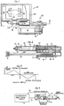
- FIG. 1 wherein there is illustrated a straight line shear generally identified by the numeral 116.
- This shear in simple terms, includes a support or frame 22 which has suitable guides for a pair of opposed slides 24, 26 which are mounted within the support 22 for simultaneous reciprocation towards and away from one another.
- the slides 24, 26 carry blades 28, 30 which cooperate with one another for the purpose of shearing a glass runner to form gobs.
- two sets of blades 28, 30 have been illustrated, it is to be understood that the shear may incorporate but a single set or may include as many as three sets or more.
- the slide 24 has a bracket 32 to which there is connected an actuating rod 34.
- the slide 26 has a similar bracket 36 to which there is coupled an actuating rod 38.
- the actuating rods 34, 38 are reciprocated by a drive assembly generally identified by the numeral 40.
- the support 22 includes a mounting plate 42 which carries a housing 44.
- the housing 44 has mounted therein a guide tube 46 in which there is guidingly mounted one end of the rod 34.
- the terminal portion of the rod 34 includes a rack 48.
- the housing 44 carries a second guide tube 50 in which there is guided for reciprocation an end portion 52 of the rod 38.
- the end portion 52 is also provided with a rack 54 which opposes the rack 48.
- a pinion 56 is positioned between the racks 48, 54 and is meshed therewith.
- the pinion 56 is keyed to a drive shaft 58 which is suitably rotatably journalled within the housing 44.
- the rod 38 is actually a piston rod of a double-acting linear air motor or cylinder generally identified by the reference numeral 106.
- the air motor 106 includes a cylinder 108 in which a piston 110 is mounted, and which piston 110 has a piston rod 112 which is coupled to or may form the rod 38.
- the piston rod 112 also extends out through the opposite end of the cylinder and is connected to the rod portion 52.
- the shear 116 is actuated utilising the double-acting air motor 106.
- a servo motor 68 is utilised to supplement the drive provided by the air cylinder 106.
- FIG. 4 it will be seen that there is illustrated a schematic of the drive for the electrical servo motor 68.
- Actuation of the servo motor 68 is primarily by means of a microprocessor which provides the shear motion profile, the microprocessor being identified by the numeral 70.
- the microprocessor 70 has an output 72 connected to a servo controller 74 which effects powder switching.
- the servo controller 74 has an output 76 connected to a control head 78 of the servo motor 68 for controlling actuation of the servo motor 68.
- the control system includes a feedback 80 from the control head 78 to the microprocessor 70. There is also a tachometer feedback 82 from the control head 78 to the servo controller.
- Sufficient air pressure is supplied to the air cylinder 106 to move the shear in excess of the desired cutting velocity.
- the microprocessor 70 provides a signal to the electric air control valve to apply air to the cylinder to move the shear for the cutting of a gob.
- the air motor cannot actuate the shear until the servo motor 68 permits such movement.
- the servo motor 68 controls the motion of the cutting stroke and the air motor provides the power.
- the torque applied to the pinion by the servo motor supplements the force applied to the shear by the air cylinder.
Landscapes
- Chemical & Material Sciences (AREA)
- Engineering & Computer Science (AREA)
- Materials Engineering (AREA)
- Organic Chemistry (AREA)
- Transmission Devices (AREA)
- Connection Of Motors, Electrical Generators, Mechanical Devices, And The Like (AREA)
- Surgical Instruments (AREA)
- Dry Shavers And Clippers (AREA)
- Mechanical Treatment Of Semiconductor (AREA)
- Shearing Machines (AREA)
Claims (4)
Applications Claiming Priority (2)
| Application Number | Priority Date | Filing Date | Title |
|---|---|---|---|
| US731300 | 1985-05-07 | ||
| US06/731,300 US4699643A (en) | 1985-05-07 | 1985-05-07 | Straight line shear |
Publications (2)
| Publication Number | Publication Date |
|---|---|
| EP0202809A1 EP0202809A1 (de) | 1986-11-26 |
| EP0202809B1 true EP0202809B1 (de) | 1990-01-31 |
Family
ID=24938931
Family Applications (1)
| Application Number | Title | Priority Date | Filing Date |
|---|---|---|---|
| EP86303408A Expired - Lifetime EP0202809B1 (de) | 1985-05-07 | 1986-05-06 | Geradliniges Schneiden |
Country Status (4)
| Country | Link |
|---|---|
| US (1) | US4699643A (de) |
| EP (1) | EP0202809B1 (de) |
| JP (1) | JP2524976B2 (de) |
| DE (1) | DE3668610D1 (de) |
Families Citing this family (17)
| Publication number | Priority date | Publication date | Assignee | Title |
|---|---|---|---|---|
| US4813994A (en) * | 1985-05-07 | 1989-03-21 | Emhart Industries, Inc. | Straight line glass gob shear |
| US4781746A (en) * | 1987-12-17 | 1988-11-01 | Emhart Industries, Inc. | Drive apparatus for straight line shear mechanism |
| US4859227A (en) * | 1989-01-27 | 1989-08-22 | Emhart Industries, Inc. | Straight line shear mechanism |
| US4869746A (en) * | 1989-02-27 | 1989-09-26 | Emhart Industries, Inc. | Straight line shear mechanism |
| JPH0796197B2 (ja) * | 1989-06-23 | 1995-10-18 | 株式会社高見沢サイバネティックス | ミシン目カッタ装置 |
| IT1241595B (it) * | 1990-12-11 | 1994-01-19 | Bottero Spa | Dispositivo di taglio di cordoni di materiale di estrusione, ad esempio cordoni di vetro fuso, per un alimentatore di una macchina operatrice per tale materiale |
| US5236489A (en) * | 1991-12-24 | 1993-08-17 | Emhart Glass Machinery Investments Inc. | Shear mechanism safety |
| US5224979A (en) * | 1991-12-24 | 1993-07-06 | Emhart Glass Machinery Investments Inc. | Top release bearing for shear mechanism |
| US5232483A (en) * | 1991-12-24 | 1993-08-03 | Emhart Glass Machinery Investments Inc. | Quick change shear assembly for glassware forming machine |
| US5486221A (en) * | 1991-12-24 | 1996-01-23 | Emhart Glass Machinery Investments Inc. | Shear mechanism for glass forming machine |
| US5180413A (en) * | 1991-12-24 | 1993-01-19 | Emhart Glass Machinery Investments Inc. | Shear mechanism for glassware forming machine |
| DE4222310A1 (de) * | 1992-07-08 | 1994-01-13 | Gps Glasprod Serv Gmbh | Vorrichtung zur Auftrennung eines oder mehrerer Stränge schmelzflüssigen Glases in einzelne Glasposten |
| US5573570A (en) * | 1994-10-13 | 1996-11-12 | Owens-Brockway Glass Container Inc. | Glass gob shearing apparatus |
| US5623995A (en) * | 1995-05-24 | 1997-04-29 | Intelagard, Inc. | Fire suppressant foam generation apparatus |
| CA2196722A1 (en) * | 1996-02-06 | 1997-08-07 | George A. Nickey | Glass gob shearing apparatus and method with internally cooled and contact lubricated blades |
| US5824128A (en) * | 1997-04-18 | 1998-10-20 | Owens-Brockway Glass Container Inc. | Glass gob shearing apparatus with improved cushioning of shear blade carriages |
| IT1294870B1 (it) * | 1997-09-17 | 1999-04-23 | Bdf Boscato & Dalla Fontana Sp | Dispositivo per il taglio di gocce di vetro fuso in uscita da un alimentatore di una macchina per la produzione di articoli di vetro. |
Citations (7)
| Publication number | Priority date | Publication date | Assignee | Title |
|---|---|---|---|---|
| US1362785A (en) * | 1917-03-22 | 1920-12-21 | Hartford Fairmont Co | Process of obtaining mold charges of glass and apparatus therefor |
| US3258104A (en) * | 1964-03-19 | 1966-06-28 | Owens Illinois Inc | Conveying and feeding glass articles into a lehr |
| DE2118132B2 (de) * | 1971-04-14 | 1972-08-31 | Fa. Hermann Heye, 4962 Obernkirchen | Antrieb fuer elemente, z.b. press-stempel und fomzangen, glasverarbeitender maschinen |
| DE1704122C3 (de) * | 1966-05-16 | 1975-09-25 | Minnesota Mining And Manufacturing Co., Saint Paul, Minn. (V.St.A.) | Verfahren und Vorrichtung zum örtlichen Versteifen eines biegsamen Werkstücks, insbesondere eines Schuhoberteils |
| DE2501109A1 (de) * | 1975-01-13 | 1976-07-15 | Maquinas Fabricacion Sa De | Verteilervorrichtung zur gleichzeitigen verteilung eines paars von chargen fuer eine glasverarbeitungsmaschine |
| WO1982003385A1 (en) * | 1981-04-02 | 1982-10-14 | Knoth Werner Dieter | Is forming machine for producing glass containers |
| US4427431A (en) * | 1981-03-30 | 1984-01-24 | Owens-Illinois, Inc. | Electronic control of a glass forming machine |
Family Cites Families (12)
| Publication number | Priority date | Publication date | Assignee | Title |
|---|---|---|---|---|
| US1987249A (en) * | 1930-02-05 | 1935-01-08 | Hazel Atlas Glass Co | Glass severing mechanism |
| US3435719A (en) * | 1967-04-24 | 1969-04-01 | Emhart Corp | Shears for molten glass feeders |
| US3592938A (en) * | 1968-04-29 | 1971-07-13 | Maul Bros Inc | Glass stream cutting apparatus |
| US3996037A (en) * | 1974-02-08 | 1976-12-07 | Emhart Industries, Inc. | Pass through shears for molten glass feeder |
| US4174647A (en) * | 1978-02-08 | 1979-11-20 | Emhart Industries, Inc. | Apparatus for straight line shearing |
| US4246820A (en) * | 1978-02-08 | 1981-01-27 | Emhart Industries, Inc. | Apparatus for straight line shearing |
| US4215611A (en) * | 1979-02-21 | 1980-08-05 | Emhart Industries, Inc. | Apparatus for straight line shearing |
| US4246819A (en) * | 1979-02-21 | 1981-01-27 | Emhart Industries, Inc. | Adjustable shear blade for a straight line shears |
| US4388100A (en) * | 1981-12-08 | 1983-06-14 | Vitro Tec Fideicomiso | Shear mechanism for machines for the manufacture of articles of glass or other materials |
| US4467431A (en) * | 1982-03-01 | 1984-08-21 | Emhart Industries, Inc. | Apparatus and method for controlling the shears of a glassware forming machine |
| US4450741A (en) * | 1982-07-14 | 1984-05-29 | Owens-Illinois, Inc. | Multiple gob shearing mechanism operating in a straight line |
| US4557746A (en) * | 1983-08-04 | 1985-12-10 | Emhart Industries, Inc. | Electro-pneumatic actuator for glassware forming machine |
-
1985
- 1985-05-07 US US06/731,300 patent/US4699643A/en not_active Expired - Fee Related
-
1986
- 1986-05-06 DE DE8686303408T patent/DE3668610D1/de not_active Expired - Fee Related
- 1986-05-06 EP EP86303408A patent/EP0202809B1/de not_active Expired - Lifetime
- 1986-05-07 JP JP61104579A patent/JP2524976B2/ja not_active Expired - Lifetime
Patent Citations (7)
| Publication number | Priority date | Publication date | Assignee | Title |
|---|---|---|---|---|
| US1362785A (en) * | 1917-03-22 | 1920-12-21 | Hartford Fairmont Co | Process of obtaining mold charges of glass and apparatus therefor |
| US3258104A (en) * | 1964-03-19 | 1966-06-28 | Owens Illinois Inc | Conveying and feeding glass articles into a lehr |
| DE1704122C3 (de) * | 1966-05-16 | 1975-09-25 | Minnesota Mining And Manufacturing Co., Saint Paul, Minn. (V.St.A.) | Verfahren und Vorrichtung zum örtlichen Versteifen eines biegsamen Werkstücks, insbesondere eines Schuhoberteils |
| DE2118132B2 (de) * | 1971-04-14 | 1972-08-31 | Fa. Hermann Heye, 4962 Obernkirchen | Antrieb fuer elemente, z.b. press-stempel und fomzangen, glasverarbeitender maschinen |
| DE2501109A1 (de) * | 1975-01-13 | 1976-07-15 | Maquinas Fabricacion Sa De | Verteilervorrichtung zur gleichzeitigen verteilung eines paars von chargen fuer eine glasverarbeitungsmaschine |
| US4427431A (en) * | 1981-03-30 | 1984-01-24 | Owens-Illinois, Inc. | Electronic control of a glass forming machine |
| WO1982003385A1 (en) * | 1981-04-02 | 1982-10-14 | Knoth Werner Dieter | Is forming machine for producing glass containers |
Also Published As
| Publication number | Publication date |
|---|---|
| JPS6212619A (ja) | 1987-01-21 |
| JP2524976B2 (ja) | 1996-08-14 |
| DE3668610D1 (de) | 1990-03-08 |
| EP0202809A1 (de) | 1986-11-26 |
| US4699643A (en) | 1987-10-13 |
Similar Documents
| Publication | Publication Date | Title |
|---|---|---|
| EP0202809B1 (de) | Geradliniges Schneiden | |
| PL312619A1 (en) | Method of operation of rotational door drive mechanism | |
| US4813994A (en) | Straight line glass gob shear | |
| US5105700A (en) | Tube cutting apparatus and method | |
| IT1196233B (it) | Pressa,particolarmente pressa per piegare pezzi in forma di foglio | |
| CZ265295A3 (en) | Cutting-off device for separating gob | |
| EP0152122B2 (de) | Kompakte Schere mit Abfallschere | |
| US4739490A (en) | Reciprocating travelling shear with plural NC controllers | |
| EP0606539B1 (de) | Servogesteuerte Rechtwinkelschere | |
| EP0612698B1 (de) | Glasspeisevorrichtung mit mehreren Öffnungen | |
| JPS57212398A (en) | Apparatus for changing angle of variable vane of pump | |
| ATE193000T1 (de) | Schneidevorrichtung, insbesondere für geschmolzene glastropfen | |
| US4993292A (en) | Notching machine | |
| ES2184771T3 (es) | Cizalla mecanica para el corte en caliente de palanquillas o barras metalicas. | |
| EP0549302B1 (de) | Abschneidescherenmechanismus für eine Glasformmaschine | |
| GB2174694A (en) | Crank drive mechanism for straight line shear | |
| JPS61270223A (ja) | ガラスのゴブ等を形成する直線剪断装置 | |
| KR830008807A (ko) | 전자-유압 로보트 위치제어 시스템 | |
| EP0203740A1 (de) | Geradliniges Schneiden mit Scherenkurve | |
| GB2249090A (en) | Apparatus for severing gobs from glass streams | |
| CN118023328A (zh) | 挤压残留物剪切机及用于剪断挤压残留物的方法 | |
| CN2451582Y (zh) | 伺服式平行剪供料机 | |
| TH7460A (th) | เครื่องควบคุมการทำงานของหน้าต่าง | |
| TH7460EX (th) | เครื่องควบคุมการทำงานของหน้าต่าง | |
| IT1182276B (it) | Dispositivo attuatore elettro pneumatico per una macchina per la formatura di articoli di vetro |
Legal Events
| Date | Code | Title | Description |
|---|---|---|---|
| PUAI | Public reference made under article 153(3) epc to a published international application that has entered the european phase |
Free format text: ORIGINAL CODE: 0009012 |
|
| AK | Designated contracting states |
Kind code of ref document: A1 Designated state(s): DE FR GB IT |
|
| 17P | Request for examination filed |
Effective date: 19870508 |
|
| 17Q | First examination report despatched |
Effective date: 19880920 |
|
| GRAA | (expected) grant |
Free format text: ORIGINAL CODE: 0009210 |
|
| AK | Designated contracting states |
Kind code of ref document: B1 Designated state(s): DE FR GB IT |
|
| REF | Corresponds to: |
Ref document number: 3668610 Country of ref document: DE Date of ref document: 19900308 |
|
| RAP2 | Party data changed (patent owner data changed or rights of a patent transferred) |
Owner name: EMHART INDUSTRIES, INC. |
|
| ET | Fr: translation filed | ||
| ITF | It: translation for a ep patent filed |
Owner name: UFFICIO BREVETTI RICCARDI & C. |
|
| PLBE | No opposition filed within time limit |
Free format text: ORIGINAL CODE: 0009261 |
|
| STAA | Information on the status of an ep patent application or granted ep patent |
Free format text: STATUS: NO OPPOSITION FILED WITHIN TIME LIMIT |
|
| 26N | No opposition filed | ||
| REG | Reference to a national code |
Ref country code: GB Ref legal event code: 732 |
|
| REG | Reference to a national code |
Ref country code: FR Ref legal event code: TP |
|
| PGFP | Annual fee paid to national office [announced via postgrant information from national office to epo] |
Ref country code: FR Payment date: 19930409 Year of fee payment: 8 |
|
| PGFP | Annual fee paid to national office [announced via postgrant information from national office to epo] |
Ref country code: DE Payment date: 19930414 Year of fee payment: 8 |
|
| PGFP | Annual fee paid to national office [announced via postgrant information from national office to epo] |
Ref country code: GB Payment date: 19930416 Year of fee payment: 8 |
|
| ITPR | It: changes in ownership of a european patent |
Owner name: CESSIONE;EMHART GLASS MACHINERY INC. |
|
| ITTA | It: last paid annual fee | ||
| PG25 | Lapsed in a contracting state [announced via postgrant information from national office to epo] |
Ref country code: GB Effective date: 19940506 |
|
| GBPC | Gb: european patent ceased through non-payment of renewal fee |
Effective date: 19940506 |
|
| PG25 | Lapsed in a contracting state [announced via postgrant information from national office to epo] |
Ref country code: FR Effective date: 19950131 |
|
| PG25 | Lapsed in a contracting state [announced via postgrant information from national office to epo] |
Ref country code: DE Effective date: 19950201 |
|
| REG | Reference to a national code |
Ref country code: FR Ref legal event code: ST |
|
| PG25 | Lapsed in a contracting state [announced via postgrant information from national office to epo] |
Ref country code: IT Free format text: LAPSE BECAUSE OF NON-PAYMENT OF DUE FEES;WARNING: LAPSES OF ITALIAN PATENTS WITH EFFECTIVE DATE BEFORE 2007 MAY HAVE OCCURRED AT ANY TIME BEFORE 2007. THE CORRECT EFFECTIVE DATE MAY BE DIFFERENT FROM THE ONE RECORDED. Effective date: 20050506 |