EP0202779A1 - Deflection and topography assessment mechanism anthropomorphically natural - Google Patents
Deflection and topography assessment mechanism anthropomorphically natural Download PDFInfo
- Publication number
- EP0202779A1 EP0202779A1 EP86302966A EP86302966A EP0202779A1 EP 0202779 A1 EP0202779 A1 EP 0202779A1 EP 86302966 A EP86302966 A EP 86302966A EP 86302966 A EP86302966 A EP 86302966A EP 0202779 A1 EP0202779 A1 EP 0202779A1
- Authority
- EP
- European Patent Office
- Prior art keywords
- humanoid
- segments
- stack
- relative movement
- bodily
- Prior art date
- Legal status (The legal status is an assumption and is not a legal conclusion. Google has not performed a legal analysis and makes no representation as to the accuracy of the status listed.)
- Granted
Links
- 230000007246 mechanism Effects 0.000 title description 31
- 238000012876 topography Methods 0.000 title 1
- 210000003127 knee Anatomy 0.000 claims abstract description 30
- 210000001624 hip Anatomy 0.000 claims description 29
- 238000005259 measurement Methods 0.000 claims description 18
- 210000002414 leg Anatomy 0.000 claims description 17
- 210000004394 hip joint Anatomy 0.000 claims description 13
- 210000000629 knee joint Anatomy 0.000 claims description 7
- 125000006850 spacer group Chemical group 0.000 claims description 3
- 238000005452 bending Methods 0.000 claims 1
- 230000003187 abdominal effect Effects 0.000 abstract description 5
- 210000003414 extremity Anatomy 0.000 abstract description 5
- 230000008859 change Effects 0.000 description 12
- 210000001015 abdomen Anatomy 0.000 description 6
- 230000000712 assembly Effects 0.000 description 4
- 238000000429 assembly Methods 0.000 description 4
- 238000010276 construction Methods 0.000 description 4
- 210000001503 joint Anatomy 0.000 description 4
- 239000000463 material Substances 0.000 description 4
- 238000012360 testing method Methods 0.000 description 4
- 239000002184 metal Substances 0.000 description 3
- 210000004197 pelvis Anatomy 0.000 description 3
- 210000003423 ankle Anatomy 0.000 description 2
- 230000006835 compression Effects 0.000 description 2
- 238000007906 compression Methods 0.000 description 2
- 230000004048 modification Effects 0.000 description 2
- 238000012986 modification Methods 0.000 description 2
- 230000000284 resting effect Effects 0.000 description 2
- 239000000725 suspension Substances 0.000 description 2
- 229920002972 Acrylic fiber Polymers 0.000 description 1
- 208000008035 Back Pain Diseases 0.000 description 1
- 229920004943 Delrin® Polymers 0.000 description 1
- 208000008930 Low Back Pain Diseases 0.000 description 1
- 229910000831 Steel Inorganic materials 0.000 description 1
- 230000004308 accommodation Effects 0.000 description 1
- 230000006978 adaptation Effects 0.000 description 1
- 230000002596 correlated effect Effects 0.000 description 1
- 230000008878 coupling Effects 0.000 description 1
- 238000010168 coupling process Methods 0.000 description 1
- 238000005859 coupling reaction Methods 0.000 description 1
- 230000002950 deficient Effects 0.000 description 1
- 238000013461 design Methods 0.000 description 1
- 238000006073 displacement reaction Methods 0.000 description 1
- 230000000694 effects Effects 0.000 description 1
- 210000001513 elbow Anatomy 0.000 description 1
- 239000004744 fabric Substances 0.000 description 1
- 238000000034 method Methods 0.000 description 1
- 210000003739 neck Anatomy 0.000 description 1
- 230000004044 response Effects 0.000 description 1
- 230000000717 retained effect Effects 0.000 description 1
- 210000002832 shoulder Anatomy 0.000 description 1
- 229920002379 silicone rubber Polymers 0.000 description 1
- 239000004945 silicone rubber Substances 0.000 description 1
- 239000010959 steel Substances 0.000 description 1
- 210000005010 torso Anatomy 0.000 description 1
- 230000001755 vocal effect Effects 0.000 description 1
Images


Classifications
-
- G—PHYSICS
- G01—MEASURING; TESTING
- G01B—MEASURING LENGTH, THICKNESS OR SIMILAR LINEAR DIMENSIONS; MEASURING ANGLES; MEASURING AREAS; MEASURING IRREGULARITIES OF SURFACES OR CONTOURS
- G01B21/00—Measuring arrangements or details thereof, where the measuring technique is not covered by the other groups of this subclass, unspecified or not relevant
- G01B21/20—Measuring arrangements or details thereof, where the measuring technique is not covered by the other groups of this subclass, unspecified or not relevant for measuring contours or curvatures, e.g. determining profile
-
- A—HUMAN NECESSITIES
- A47—FURNITURE; DOMESTIC ARTICLES OR APPLIANCES; COFFEE MILLS; SPICE MILLS; SUCTION CLEANERS IN GENERAL
- A47C—CHAIRS; SOFAS; BEDS
- A47C31/00—Details or accessories for chairs, beds, or the like, not provided for in other groups of this subclass, e.g. upholstery fasteners, mattress protectors, stretching devices for mattress nets
- A47C31/12—Means, e.g. measuring means, for adapting chairs, beds or mattresses to the shape or weight of persons
- A47C31/123—Means, e.g. measuring means, for adapting chairs, beds or mattresses to the shape or weight of persons for beds or mattresses
-
- A—HUMAN NECESSITIES
- A47—FURNITURE; DOMESTIC ARTICLES OR APPLIANCES; COFFEE MILLS; SPICE MILLS; SUCTION CLEANERS IN GENERAL
- A47C—CHAIRS; SOFAS; BEDS
- A47C31/00—Details or accessories for chairs, beds, or the like, not provided for in other groups of this subclass, e.g. upholstery fasteners, mattress protectors, stretching devices for mattress nets
-
- A—HUMAN NECESSITIES
- A61—MEDICAL OR VETERINARY SCIENCE; HYGIENE
- A61B—DIAGNOSIS; SURGERY; IDENTIFICATION
- A61B5/00—Measuring for diagnostic purposes; Identification of persons
- A61B5/103—Measuring devices for testing the shape, pattern, colour, size or movement of the body or parts thereof, for diagnostic purposes
-
- G—PHYSICS
- G01—MEASURING; TESTING
- G01B—MEASURING LENGTH, THICKNESS OR SIMILAR LINEAR DIMENSIONS; MEASURING ANGLES; MEASURING AREAS; MEASURING IRREGULARITIES OF SURFACES OR CONTOURS
- G01B7/00—Measuring arrangements characterised by the use of electric or magnetic techniques
- G01B7/28—Measuring arrangements characterised by the use of electric or magnetic techniques for measuring contours or curvatures
- G01B7/287—Measuring arrangements characterised by the use of electric or magnetic techniques for measuring contours or curvatures using a plurality of fixed, simultaneously operating transducers
-
- G—PHYSICS
- G09—EDUCATION; CRYPTOGRAPHY; DISPLAY; ADVERTISING; SEALS
- G09B—EDUCATIONAL OR DEMONSTRATION APPLIANCES; APPLIANCES FOR TEACHING, OR COMMUNICATING WITH, THE BLIND, DEAF OR MUTE; MODELS; PLANETARIA; GLOBES; MAPS; DIAGRAMS
- G09B23/00—Models for scientific, medical, or mathematical purposes, e.g. full-sized devices for demonstration purposes
- G09B23/28—Models for scientific, medical, or mathematical purposes, e.g. full-sized devices for demonstration purposes for medicine
- G09B23/30—Anatomical models
- G09B23/32—Anatomical models with moving parts
-
- A—HUMAN NECESSITIES
- A61—MEDICAL OR VETERINARY SCIENCE; HYGIENE
- A61B—DIAGNOSIS; SURGERY; IDENTIFICATION
- A61B2562/00—Details of sensors; Constructional details of sensor housings or probes; Accessories for sensors
- A61B2562/04—Arrangements of multiple sensors of the same type
- A61B2562/046—Arrangements of multiple sensors of the same type in a matrix array
-
- A—HUMAN NECESSITIES
- A61—MEDICAL OR VETERINARY SCIENCE; HYGIENE
- A61B—DIAGNOSIS; SURGERY; IDENTIFICATION
- A61B5/00—Measuring for diagnostic purposes; Identification of persons
- A61B5/45—For evaluating or diagnosing the musculoskeletal system or teeth
- A61B5/4528—Joints
-
- A—HUMAN NECESSITIES
- A61—MEDICAL OR VETERINARY SCIENCE; HYGIENE
- A61B—DIAGNOSIS; SURGERY; IDENTIFICATION
- A61B5/00—Measuring for diagnostic purposes; Identification of persons
- A61B5/45—For evaluating or diagnosing the musculoskeletal system or teeth
- A61B5/4538—Evaluating a particular part of the muscoloskeletal system or a particular medical condition
- A61B5/4561—Evaluating static posture, e.g. undesirable back curvature
Definitions
- This invention is related to an apparatus for measuring the shape or contour of a surface in relation to the form of the human body. That is, the invention yields an indication of surface contour as reflected by position changes of bodily parts of a human-shaped figure placed on the surface.
- the invention relates to an apparatus useful in measuring the shape or contour of a mattress surface under load from such a human-shaped figure.
- the present invention has its genesis in the field of mattress construction.
- mattresses have an innerspring assembly composed of a plurality of coil springs which are arranged in a pattern within a border wire framework, with the coils and framework joined together in an integral whole.
- innerspring assembly composed of a plurality of coil springs which are arranged in a pattern within a border wire framework, with the coils and framework joined together in an integral whole.
- multiple layers of insulative and other sheet material overlie the innerspring assembly, culminating in an outer covering layer of soft fabric.
- One objective in designing a mattress is to optimize the distribution of pressure over the human body in a "deformed” profile, e.g., sleep position, while also providing satisfactory firmness.
- This objective has been quantified in one instance as an "idealized support profile” or model.
- one known way to measure the shape or contour of the mattress is to test it under load at various discrete points, typically along a line extending parallel to the longitudinal axis of the mattress. These individual data points can then be plotted to give an indication of the mattress "firmness" along that line.
- This method of measuring mattress contour is deficient in that the information obtained is only of a relatively small discrete area under load, and does not reflect shape or contour of the mattress under a wide area load, such as the human body.
- the measurement also takes an undesirable length of time to obtain, in light of the fact that a plurality of point measurements must be taken, typically one at a time.
- a present invention which is comprised of a humanoid having body limb extremities similar in size and shape to those of the human body.
- One or more of those extremities is made to be movable in a manner similar to the movement of a comparable human extremity, at least in one plane of motion.
- a present embodiment of the invention provides for movement of the humanoid leg at the knee joint and the hip joint such that the leg can bend or rotate at these joints in a plane parallel to a plane bisecting the humanoid figure, i.e., in a vertical plane if the humanoid is lying horizontally on its back.
- the humanoid is further constructed in a manner which at least grossly reproduces the size and shape of the human body, including its relative hardness or softness in certain areas, as well as its areas of higher or lower mass (i.e., its weight is distributed in proportion to the male human body).
- Positional sensing devices are located at selected points on the humanoid figure.
- the sensing devices detect the amount of relative movement, or deflection, which that area of the figure undergoes when placed in contact with a surface to be measured.
- a present embodiment of the invention locates position transducers in the form of rotary potentiometers at the hip and knee joints to indicate the deflection in these areas caused by the surface configuration.
- a device reproducing a portion of the human spine is also advantageously provided, and has an associated positional sensing mechanism for indicating deflection in the area of the lower back/abdomen.
- This present embodiment of the invention further includes a movable support assembly from which the humanoid is horizontally suspended, such that it can be readily lowered onto and raised from a surface to be measured.
- the movable support is in the form of a motor driven frame which moves up and down a set of supporting legs, with the humanoid suspended below the frame.
- the humanoid In use, the humanoid is lowered by the support mechanism into contact with a surface which is to have its shape or contour measured, such as a mattress.
- the humanoid is allowed to rest with its full weight supported by the mattress surface. Movements of the legs, hips and lower back/abdomen caused by the mattress surface contour are detected by the position transducers in the form of voltage changes in the transducer circuit. These voltage changes can then be translated into a measurement of the contour of the surface as reflected by the relative changes in position of the humanoid's joints and "spine."
- the invention provides a means for measurement of mattress contour under a wide area load of a human figure. This actual mattress contour can then be compared to the "idealized support profile" for example, to determine how closely the mattress matches such a desired configuration.
- measurement of a surface contour is a principal objective of this invention
- measurement of the effect of a surface contour on the humanoid is also of separate significance. That is, changes in position of the humanoid's bodily parts caused by the surface can be related to likely human body responses, e.g., deflection in the abdominal area resulting in low back pain.
- This invention can thus be utilized in measuring a surface contour, as well as estimating its physiological impact on the human body.
- this embodiment of the invention is generally comprised of a humanoid figure 10 which is suspended in a supine (horizontal) position beneath a movable support assembly 11.
- the humanoid 10 is raised and lowered in relation to a mattress 12 supported on a box spring 13.
- the humanoid 10 can be purchased from Humanoid Systems, 17022 Montanero St., Carson, California 90746. It is a Model No. 572 dummy of a type commonly used in crash testing, for example, which has been modified in certain respects pertinent to this invention, as will be more fully described below.
- the humanoid 10 is anthropomorphically "natural", reproducing the size, shape and weight of a human being of approximately 192 pounds.
- the unmodified humanoid 10 generally reproduces the movement of the major joints of the human body, e.g. ankle, knee, hip, torso, elbow, shoulder, neck. It also grossly reproduces areas of relative hardness and softness on the human body, as well as the mass distribution of the human body, including localized areas of higher or lower mass.
- the humanoid 10 thus generally reproduces the . shape, "feel” and relative mass distribution of the human body, as well as the range of movement of the major joints.
- the humanoid 10 is suspended in a supine position (i.e., with its ventral side facing upwardly) from a plate 15, such as a thick plate of transparent acrylic plastic, which is part of the movable support assembly 11.
- a plurality of cables 16, such as common aircraft cables, are fixed at one end to the ventral side of the humanoid 10 at convenient points, with the other end of the cables 16 fixed to the plate 15, generally directly above their respective points of attachment on the humanoid 10.
- the location points of the cables 16 on the humanoid figure 10 are not considered to be critical, but should be sufficient in number to maintain the humanoid figure 10 in a straight, relatively horizontal position when the humanoid is not resting on a surface. Some suitable mechanism permitting minor adjustments of cable length may also be used, such as an adjustable coupling mechanism. Flexible cables 16 are used which go slack when the humanoid 10 is resting with its full weight upon the mattress 12.
- Plate 15 is connected by a plurality of brackets 18 to the underside of a support frame 19, which is mounted for movement along four vertically extending legs 20.
- a suitable drive mechanism schematically illustrated at 22 is used to drive the support frame 19 up and down the legs 20.
- the entire movable support assembly 11 used in the illustrated embodiment is a modified common hospital bed Model No. 671 available from Joerns, 5555 Joerns Drive, Stephens Point, Wisconsin 54481.
- the plate 15 is installed on the Joerns bedframe, with the humanoid 10 thus suspended below the bedframe.
- Extended legs 20 were used with the bedframe for the necessary height.
- the drive mechanism 22 provided with the aforementioned Joerns hospital bed frame is utilized herein.
- this invention is useful in measuring the shape or contour of a surface as reflected in the deflection, or relative change in position, of various parts of a human-like body.
- the humanoid 10 described herein has been particularly modified to make such a measurement of deflection in the area of the humanoid's knees (knee mechanism 25), hips (hip joint mechanism 26) and lower back/abdominal region, i.e., lower spine (spine mechanism 27).
- deflection in a vertical plane i.e., in a plane parallel to an imaginary plane bisecting the humanoid figure 10.
- No horizontal movements of the bodily parts of the figure are measured herein.
- Adaptation of the invention to measure such horizontal movements, as well as additional movements in a vertical plane other than those described herein are of course within the broad concept of this invention.
- the device for measuring the deflection of the knee is particularly shown in Figs. 2-4.
- the knee mechanism of the aforementioned stock humanoid figure is modified through the addition of a large spur gear 29 which is fixed to a plate 30 on the inboard side of the knee concentric with a pivot pin 31 about which plate 30 pivots.
- plate 30 and large spur gear 29 move with the lower leg.
- the spur gear 29 can be fixed in position by any suitable means, as by screws 33.
- a standard rotary potentiometer 36a such as a Model 50-M125 rotary potentiometer available from Maurey Instruments, 4555 West 60th Street, Chicago, Illinois.
- the rotary potentiometer 36a and associated small spur gear 35 are mounted on a bracket 38 which is fixed to a plate 34 forming part of the humanoid's general knee mechanism, as by screws 39.
- the plate 34 and bracket 39 move with the upper leg.
- a portion of the potentiometer 36a also extends through a bore 40 formed in a portion 41 making up the general knee mechanism of the stock humanoid. This bore 40 is simply an accommodation for the size of the potentiometer.
- the potentiometer 36a as well as the other potentiometers described hereinafter, are each connected in a circuit having a suitable power supply and voltage metering device (both schematically indicated at 45 in Fig. 1). Construction of the circuit is well within the ability of anyone of ordinary skill in the art, and it is simply designed to register changes in voltage in the circuit when the variable resistance of the rotary potentiometer is changed, as in the manner hereinafter described.
- the large spur gear 29 is fixed to a portion of the humanoid's knee which rotates independently of the portion of the knee mechanism to which the small spur gear 35 and associated potentiometer 36a are mounted.
- the knee mechanism 25 is deflected, such as when the humanoid 10 is placed on the surface 12a of the mattress, the aforedescribed portions of the knee move relative to one another, thereby causing the small spur gear 35 to be rotated, which in turn drives the potentiometer 36a.
- the change in voltage caused by this resistance change in the potentiometer is then detected at meter 45. That signal can then be translated into a measurement of deflection, i.e., vertical movement of the knee mechanism 25.
- Deflection of the knee is of course caused by the contour of the surface under the knee, thus yielding a measurement of surface contour which is directly related to positional changes caused in the knee mechanism 25. It may be additionally noted that by proper zeroing of the potentiometer 36a, deflection of the knee mechanism 25 upwardly as well as downwardly can be registered.
- Both knee mechanisms 25 are identical, so only one need be described in detail herein. Likewise, only one hip mechanism 26 will be described in detail, since both are also identical.
- the hip mechanism 26 of the humanoid 10 is illustrated in Figs. 5 and 6. It is modified from the stock humanoid by inserting an elongated metal pin 50 through the approximate center of a ball portion 51 of a hip stem 52 along a line extending substantially perpendicular to the aforementioned imaginary vertical plane bisecting the humanoid 10.
- the pin 50 extends completely through the ball portion 51 and into a bore 53 formed in the metal pelvic portion 54 of the humanoid 10.
- the pin 50 is fixed within the ball portion 51, but is free to rotate in the bore 53. Pinning the hip stem 52 in this manner permits it to only rotate in a vertical plane, i.e., the normal three dimensional movement of this ball and socket joint is restricted to rotation about this pin 50.
- An L-shaped bracket 55 is fixed at one end within a channel 56 formed in the metal of the pelvic portion 54 of the humanoid 10, as by screws 58.
- the other end of the bracket 55 extends downwardly, with a mounting plate 57 fixed thereto which carries another rotary potentiometer 36b.
- the potentiometer 36b is of the same type as potentiometer 36a.
- Potentiometer 36b is mounted to extend through a hole 59 formed in the plate 57, with the potentiometer stem 37b extending inboard.
- the mounting plate 57 is attached to the bracket 55 by screws 60 which extend through associated bores 61 that are slightly elongated in the vertical direction. This provides some adjustability for the plate 57 to generally align the potentiometer stem 37b with the pin 50 to which the potentiometer 36b is connected in the following manner.
- Pin 50 has a portion 62 which extends outboard from the ball portion 51 of the hip stem 52.
- the potentiometer stem 37b is connected to this portion 62 of the hip pin 50 by a tubular flexible connector 68.
- the ends of this connector 68 are respectively attached, as by clamps 69, to the potentiometer stem 37b and the hip pin portion 62. It will be noted that no particular significance is placed on the type of connector 68 used herein, but a flexible connector is deemed desirable to allow some leeway in alignment of the potentiometer stem and hip pin.
- the hip pin 50 is fixed within the ball portion 51 of the hip stem 52, and therefore rotates with the ball portion 51. Rotation of the ball portion 51 thus rotates the potentiometer stem 37b via the connector 68, changing the potentiometer's resistance. The change in potential in the circuit in which potentiometer 36b is connected is then metered.
- Rotary movement of the hip stem 37b results from movement of the upper leg relative to the pelvis. A measurement of surface contour beneath each of the hips, as reflected in this deflection, is thereby obtained. By proper zeroing of the potentiometer 36b, deflection of each of the hips upwardly as well as downwardly can be measured.
- Relative movements of the lower torso and pelvis of the humanoid i.e., in the area of the lower back/abdomen, is also detected and measured.
- the stock humanoid is modified to this end by the placement of a spine mechanism 27 in this area.
- the spine mechanism 27 includes a spinal stack or column 75 which is composed of a plurality of "vertebra" in the form of intermediate discs 76a and end discs 76b.
- the discs 76a, 76b are formed from a rigid plastic material, such as Delrin, available from Dupont Corp.
- the discs 76a have generally hemispherically shaped hollows 78 formed on opposed sides of each intermediate disc 76a substantially concentric with the axis of each disc.
- Each end disc 76b has only one hemispherical hollow formed on the inboard side of the disc.
- the two discs 76b essentially serve as end caps for the spinal column 75.
- a plurality of balls 79 are received in the opposed hemispherical hollows of adjacent discs 76a, 76b.
- Resilient ring spacers 82 made of a low durometer material, such as silicone rubber, are received in annular recesses 83 formed in the discs 76a, 76b substantially concentric with the disc axis.
- the recesses 83 are designed to oppose each other on assembly of the spinal column 75, such that a portion of a ring 82 is received and thereby carried within each of a pair of opposed recesses 83.
- the rings 82 are of a sufficient thickness such that adjacent discs 76a, 76b are spaced at least slightly apart upon assembly of the spinal column 75.
- the rings 82 provide a degree of resiliency to the column 75, and further serve to bias the discs 76a, 76b toward a straight stack configuration.
- Spinal column 75 is completed by a cable 85 which extends along the longitudinal axis of the stacked discs 76a, 76b through a longitudinal channel 86 which extends through the discs and balls.
- Each end of the cable 85 is fixed in a bore 88 in a flange portion 87 formed on the outboard side of each disc 76b. It has been found advantageous herein to form screw threads about the cable ends and provide at least one threaded bore 88 in the flange portions 87 to thereby allow a disc 76b to be rotated to adjust the compression of the spinal column 75.
- a spinal column 75 is provided which is similar in construction and movement to a portion of the human spine.
- the spinal column 75 is mounted between an upper spine support assembly 95 and a lower spine support assembly 96.
- Upper spine support assembly 95 has a spine support mount 97 which is mounted to the inboard side (i.e., side facing the spinal column 75) of an end cap 98, as by screws (not shown).
- the end cap 98 is in turn fixed in a suitable fashion within one end of a cavity 101 provided in the humanoid 10.
- Either flange portion 87 on one end of the spinal column 75 is received in an elongated horizontal recess or slot 105 formed in the inboard side of the upper spine mount 97.
- Flange portion 87 is releasably retained in place through the use of set screws 106 extending through a pair of threaded bores 107 and received in suitable detents 89 formed in each flange portion 87 (best shown with reference to Fig. 10).
- the flange portion 87 of the other end of the spinal column 75 is likewise received in an elongated recess or slot 108 formed in the inboard side of a lower spine mount 109.
- a like pair of set screws 106 extend through threaded bores 107 in the lower spinal mount 109, and are received in detents 89 formed in the flange portion 87.
- Lower spine mount 109 is fixed to the inboard side of a lower end cap 110, as by screws 111.
- Lower end cap 110 is in turn fixed in a suitable fashion within the other end of the cavity 101 provided in the humanoid 10.
- spinal column 75 serves to interconnect the torso of the humanoid 10 with its pelvic area. The humanoid 10 is otherwise freely movable in this region..
- a sensor is provided to measure relative vertical movement or shear of the upper and lower spine assemblies 95, 96.
- a bracket 99 is fixed at one end to the lower end cap 110. The other end of the bracket 99 is free and is located adjacent upper end cap 98.
- a potentiometer 36e is mounted to the free end of bracket 99, and has a lever arm 100 extending radially from its stem 37e. Lever arm 100 is pivotally connected to a link 102, which in turn is connected to the upwardly facing side of upper end cap 98.
- a pair of relatively flexible wires 115a and 115b extend generally parallel to the spinal column 75, with wire 115a located upwardly from the spinal column, and wire 115b located beneath the spinal column (as the spinal column 75 is viewed in Fig. 1, for example).
- the two wires 115a, 115b are in the same generally vertical plane, i.e., the imaginary vertical plane bisecting the humanoid 10.
- Wire 115a is fixed at one end in the upper spine mount 97.
- this end of wire 115a is swaged, with the swaged end received in a well 117a having a bore 118a through which wire 115a extends.
- the other end of wire 115a extends through a bore 116a which passes through lower spine mount 109 and into a cavity 120 within the lower end cap 110.
- lower wire 115b is fixed to upper spine mount 97, having its swaged end received in a well 117b having a bore 118b, and extends through a bore 116b through the lower spine mount 109 and into the cavity 120.
- a pair of rotary potentiometers 36c and 36d are mounted to a housing 119 fixed within the end cap 110.
- Rotary potentiometer 36c has a lever arm 121 which is fixed to its potentiometer stem 37c and extends radially therefrom.
- the lever arm 121 has a lug 122 on its unfixed end to which the upper cable 115a is attached.
- Potentiometer 36d in a similar fashion, has a lever arm 123 fixed to its potentiometer stem 37d, with a lug 125 located on its unfixed end to which the lower wire 115b is attached.
- a spring 126 is connected between each of the lever arms 121, 123 and on outboard spring mount 127 fixed within end cap 110.
- the springs 126 serve to bias the lever arms 121, 123 to a "start" or zero position.
- the spinal column 75 When the abdominal region of the humanoid 10 is deflected upwardly or downwardly, the spinal column 75 will bend in a like manner. This permits the upper and lower spine support assemblies 95, 96 to pivot or cant upwardly or downwardly in relation to the movement of the spinal column 75. This canting in turn pulls one of the wires 115a, 115b against the spring bias. The other wire conversely yields to its spring bias, i.e., is pulled toward the end wall to which the spring is attached.
- the wire 115a, 115b placed under additional tension (pulled against the spring bias) causes the lever arm 121, 123 to which it is connected to be pulled toward the spinal column 75, thereby rotating the stem 37c, 37d of the associated potentiometer 36c, 36d resulting in a change of resistance therein.
- the wire 115a, 115b under reduced tension has its lever arm 121, 123 pulled away from the spinal column 75, thereby resulting in a change in resistance of its associated potentiometer 36c, 36d.
- Both potentiometers 36c and 36d are connected in a suitable circuit with power supply and metering device 45 in a manner similar to potentiometer 36a, such that a change in resistance of potentiometer 36c or 36d causes a voltage change which reflects the amount of deflection of the "spine" of the humanoid 10.
- each of the various potentiometers are zeroed to establish a base line for the humanoid 10 in a rest position, i.e., suspended in a relatively straightened supine position from the movable support assembly 11.
- the drive motor 22 of the movable support 11 is then actuated to lower the humanoid 10 onto surface 12a of the mattress 12. Lowering stops approximately at the point where the suspension cables 16 go slack, with the entire weight of the humanoid 10 then supported by the mattress 12.
- various portions of the humanoid's body will move relative to one another.
- the humanoid 10 is substantially unmodified from the stock figure obtainable from the aforementioned source. That is, no modification of the knees, hips or "spine" is made as described in the previous embodiment. Instead, a plurality of linear transducer mechanisms 140a-140j, such as Model PT-101-15A linear transducers available from Celesco Company Transducer Products, Inc., Canoga Park, California, are utilized to register relative movement of the body parts of the humanoid.
- a plurality of linear transducer mechanisms 140a-140j such as Model PT-101-15A linear transducers available from Celesco Company Transducer Products, Inc., Canoga Park, California, are utilized to register relative movement of the body parts of the humanoid.
- Each linear transducer 140a-140j has a respective cable portion 141a-141j which is connected by a suitable connector 142 at a point on the ventral side of the humanoid 10.
- transducer connector points are located at the ankles, knees, hips, lower and upper abdomen, and on both sides of the upper torso.
- Each of the linear transducers 140a-140j is located generally directly over its respective attachment point and is mounted to the lower portion of the plate 15. While any number of linear transducers can be used in this embodiment, depending on the number of data points desired, the ten transducers illustrated herein attached at the points described are presently deemed to be optimal.
- the linear transducers 140a-140j are each connected in a circuit having a suitable power supply and voltage metering device (both schematically indicated at 145 in Fig. 12). Construction of a circuit to register voltage changes caused by resistance changes in the linear transducers is well within the ability of anyone of ordinary skill in the art.
- the humanoid 10 is lowered onto a rigid surface, such as a board, laid across the mattress surface 12a.
- the various transducers 140a-140j are then zeroed to this baseline position.
- the humanoid is then raised, the board removed, and then lowered again until it comes to rest on the surface 12a of mattress 12. Lowering stops when the suspension cables 16 go slack, with the full weight of the humanoid 10 thereby supported on the mattress surface 12a.
- Movement of the various bodily parts of the humanoid 10 from the zero position, caused by settling into the mattress surface 12a and conforming to its shape and contour, will deflect the bodily parts in a manner which is registered by the associated transducers 140a-140j. Since each such deflection is caused by the contour of the mattress below the particular body part, a measurement of the shape or contour of the mattress under the wide area load of the humanoid is obtained.
- Such a measurement of mattress contour is of particular utility in designing improved mattresses.
- measurements made using this invention could indicate areas of a given mattress design which require adjustment to either increase or decrease the "firmness" in such areas, as by a change in spring arrangement, spring compression, covering material, and the like.
Landscapes
- Health & Medical Sciences (AREA)
- Physics & Mathematics (AREA)
- Engineering & Computer Science (AREA)
- General Physics & Mathematics (AREA)
- Life Sciences & Earth Sciences (AREA)
- General Health & Medical Sciences (AREA)
- Medical Informatics (AREA)
- Mathematical Analysis (AREA)
- Heart & Thoracic Surgery (AREA)
- Algebra (AREA)
- Medicinal Chemistry (AREA)
- Mathematical Optimization (AREA)
- Mathematical Physics (AREA)
- Pure & Applied Mathematics (AREA)
- Business, Economics & Management (AREA)
- Educational Administration (AREA)
- Educational Technology (AREA)
- Theoretical Computer Science (AREA)
- Dentistry (AREA)
- Oral & Maxillofacial Surgery (AREA)
- Chemical & Material Sciences (AREA)
- Biophysics (AREA)
- Pathology (AREA)
- Biomedical Technology (AREA)
- Computational Mathematics (AREA)
- Molecular Biology (AREA)
- Surgery (AREA)
- Animal Behavior & Ethology (AREA)
- Public Health (AREA)
- Veterinary Medicine (AREA)
- Measurement Of The Respiration, Hearing Ability, Form, And Blood Characteristics Of Living Organisms (AREA)
- Length Measuring Devices With Unspecified Measuring Means (AREA)
- Investigating Or Analysing Materials By Optical Means (AREA)
- A Measuring Device Byusing Mechanical Method (AREA)
- Invalid Beds And Related Equipment (AREA)
- Fertilizers (AREA)
- Catching Or Destruction (AREA)
- Artificial Fish Reefs (AREA)
- Investigating Or Analyzing Non-Biological Materials By The Use Of Chemical Means (AREA)
- Diaphragms For Electromechanical Transducers (AREA)
Abstract
Description
- This invention is related to an apparatus for measuring the shape or contour of a surface in relation to the form of the human body. That is, the invention yields an indication of surface contour as reflected by position changes of bodily parts of a human-shaped figure placed on the surface. In particular, the invention relates to an apparatus useful in measuring the shape or contour of a mattress surface under load from such a human-shaped figure.
- The present invention has its genesis in the field of mattress construction. In general, mattresses have an innerspring assembly composed of a plurality of coil springs which are arranged in a pattern within a border wire framework, with the coils and framework joined together in an integral whole. Typically, multiple layers of insulative and other sheet material overlie the innerspring assembly, culminating in an outer covering layer of soft fabric.
- One objective in designing a mattress is to optimize the distribution of pressure over the human body in a "deformed" profile, e.g., sleep position, while also providing satisfactory firmness. This objective has been quantified in one instance as an "idealized support profile" or model.
- Measuring whether a mattress matches such an idealized model, or for that matter, matches whatever contour or shape is ultimately desired for the mattress when under load by a human being, has been a relatively inexact science to date. For example, one known way to measure the shape or contour of the mattress is to test it under load at various discrete points, typically along a line extending parallel to the longitudinal axis of the mattress. These individual data points can then be plotted to give an indication of the mattress "firmness" along that line. This method of measuring mattress contour is deficient in that the information obtained is only of a relatively small discrete area under load, and does not reflect shape or contour of the mattress under a wide area load, such as the human body. The measurement also takes an undesirable length of time to obtain, in light of the fact that a plurality of point measurements must be taken, typically one at a time.
- Another known way of obtaining an indication of "feel" of a mattress is to have a group of individuals lie on the mattress surface one after another, and then compile their various verbal impressions of how the mattress "felt." While this "measurement" of the shape and surface of a mattress is plainly related to the configuration of the mattress under the wide area load of the human body, it obviously lacks objective detail, consistency and repeatability.
- It is a principal objective of this invention to provide an apparatus for use in measuring the shape or contour of a surface as reflected in positional changes of a human-shaped figure. More particularly, it is a specific objective of this invention to provide such an apparatus which can rapidly, objectively and repeatably indicate the shape or contour of a mattress surface under the deformed profile load of an object with human shape and mass distribution.
- These objectives have been met in the present invention which is comprised of a humanoid having body limb extremities similar in size and shape to those of the human body. One or more of those extremities is made to be movable in a manner similar to the movement of a comparable human extremity, at least in one plane of motion. For example, a present embodiment of the invention provides for movement of the humanoid leg at the knee joint and the hip joint such that the leg can bend or rotate at these joints in a plane parallel to a plane bisecting the humanoid figure, i.e., in a vertical plane if the humanoid is lying horizontally on its back.
- The humanoid is further constructed in a manner which at least grossly reproduces the size and shape of the human body, including its relative hardness or softness in certain areas, as well as its areas of higher or lower mass (i.e., its weight is distributed in proportion to the male human body).
- Positional sensing devices are located at selected points on the humanoid figure. The sensing devices detect the amount of relative movement, or deflection, which that area of the figure undergoes when placed in contact with a surface to be measured. For example, a present embodiment of the invention locates position transducers in the form of rotary potentiometers at the hip and knee joints to indicate the deflection in these areas caused by the surface configuration. A device reproducing a portion of the human spine is also advantageously provided, and has an associated positional sensing mechanism for indicating deflection in the area of the lower back/abdomen.
- This present embodiment of the invention further includes a movable support assembly from which the humanoid is horizontally suspended, such that it can be readily lowered onto and raised from a surface to be measured. The movable support is in the form of a motor driven frame which moves up and down a set of supporting legs, with the humanoid suspended below the frame.
- In use, the humanoid is lowered by the support mechanism into contact with a surface which is to have its shape or contour measured, such as a mattress. The humanoid is allowed to rest with its full weight supported by the mattress surface. Movements of the legs, hips and lower back/abdomen caused by the mattress surface contour are detected by the position transducers in the form of voltage changes in the transducer circuit. These voltage changes can then be translated into a measurement of the contour of the surface as reflected by the relative changes in position of the humanoid's joints and "spine."
- As applied to mattresses, the invention provides a means for measurement of mattress contour under a wide area load of a human figure. This actual mattress contour can then be compared to the "idealized support profile" for example, to determine how closely the mattress matches such a desired configuration.
- It will also be recognized that, while measurement of a surface contour is a principal objective of this invention, measurement of the effect of a surface contour on the humanoid is also of separate significance. That is, changes in position of the humanoid's bodily parts caused by the surface can be related to likely human body responses, e.g., deflection in the abdominal area resulting in low back pain. This invention can thus be utilized in measuring a surface contour, as well as estimating its physiological impact on the human body.
- The features and advantages of this invention will be more particularly understood with reference to the detailed description and drawings which follow, in which:
-
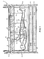
- Fig. 1 is a side elevational view of a first embodiment of the invention;
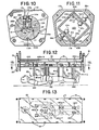
- Fig. 2 is a view of the outboard side of the knee mechanism;
- Fig. 3 is a sectional view of the knee mechanism taken along line 3-3 of Fig. 2;
- Fig. 4 is a sectional view taken along line 4-4 of Fig. 3 generally showing the inboard side of the knee mechanism;
- Fig. 5 is a plan view of the area of the hips, partly broken away for detail;
- Fig. 6 is a sectional view taken along line 6-6 of Fig. 5 showing a hip joint mechanism;
- Fig. 7 is an elevational view of the torso, partly broken away to detail placement of the spine mechanism;
- Fig. 8 shows the spine mechanism removed from the torso;
- Fig. 9 is a sectional view taken along line 9-9 of Fig. 8 detailing the spine stack or column;
- Fig. 10 is a sectional view taken along line 10-10 of Fig. 8;
- Fig. 11 is a sectional view taken along line 11-11 of Fig. 8;
- Fig. 12 is a partially diagrammatic side elevational view of a second embodiment of the invention;
- Fig. 13 is a diagrammatic sectional view taken along line 13-13 of Fig. 12 of the second embodiment of the invention showing transducer placement.
- The embodiments of the invention illustrated and described herein are particularly adapted for testing the surface and shape of a mattress. While the following description of the invention will be related to this particular environment of mattress testing, it will be understood that the invention is not necessarily so limited, but might find other applications where it is desired to measure the contour or shape of a surface, particularly a deformable surface, with reference to the shape of the human body.
- With reference to Fig. 1, this embodiment of the invention is generally comprised of a humanoid figure 10 which is suspended in a supine (horizontal) position beneath a
movable support assembly 11. Thehumanoid 10 is raised and lowered in relation to amattress 12 supported on abox spring 13. - The
humanoid 10 can be purchased from Humanoid Systems, 17022 Montanero St., Carson, California 90746. It is a Model No. 572 dummy of a type commonly used in crash testing, for example, which has been modified in certain respects pertinent to this invention, as will be more fully described below. - The
humanoid 10 is anthropomorphically "natural", reproducing the size, shape and weight of a human being of approximately 192 pounds. Theunmodified humanoid 10 generally reproduces the movement of the major joints of the human body, e.g. ankle, knee, hip, torso, elbow, shoulder, neck. It also grossly reproduces areas of relative hardness and softness on the human body, as well as the mass distribution of the human body, including localized areas of higher or lower mass. - The
humanoid 10 thus generally reproduces the . shape, "feel" and relative mass distribution of the human body, as well as the range of movement of the major joints. - The humanoid 10 is suspended in a supine position (i.e., with its ventral side facing upwardly) from a
plate 15, such as a thick plate of transparent acrylic plastic, which is part of themovable support assembly 11. A plurality ofcables 16, such as common aircraft cables, are fixed at one end to the ventral side of the humanoid 10 at convenient points, with the other end of thecables 16 fixed to theplate 15, generally directly above their respective points of attachment on the humanoid 10. - The location points of the
cables 16 on the humanoid figure 10 are not considered to be critical, but should be sufficient in number to maintain the humanoid figure 10 in a straight, relatively horizontal position when the humanoid is not resting on a surface. Some suitable mechanism permitting minor adjustments of cable length may also be used, such as an adjustable coupling mechanism.Flexible cables 16 are used which go slack when the humanoid 10 is resting with its full weight upon themattress 12. -
Plate 15 is connected by a plurality ofbrackets 18 to the underside of asupport frame 19, which is mounted for movement along four vertically extendinglegs 20. A suitable drive mechanism schematically illustrated at 22 is used to drive thesupport frame 19 up and down thelegs 20. - The entire
movable support assembly 11 used in the illustrated embodiment is a modified common hospital bed Model No. 671 available from Joerns, 5555 Joerns Drive, Stephens Point, Wisconsin 54481. Theplate 15 is installed on the Joerns bedframe, with the humanoid 10 thus suspended below the bedframe.Extended legs 20 were used with the bedframe for the necessary height. Thedrive mechanism 22 provided with the aforementioned Joerns hospital bed frame is utilized herein. - As previously set forth, this invention is useful in measuring the shape or contour of a surface as reflected in the deflection, or relative change in position, of various parts of a human-like body. The humanoid 10 described herein has been particularly modified to make such a measurement of deflection in the area of the humanoid's knees (knee mechanism 25), hips (hip joint mechanism 26) and lower back/abdominal region, i.e., lower spine (spine mechanism 27). In this embodiment, deflection in a vertical plane, i.e., in a plane parallel to an imaginary plane bisecting the humanoid figure 10, is measured. No horizontal movements of the bodily parts of the figure are measured herein. Adaptation of the invention to measure such horizontal movements, as well as additional movements in a vertical plane other than those described herein, are of course within the broad concept of this invention.
- The device for measuring the deflection of the knee is particularly shown in Figs. 2-4. The knee mechanism of the aforementioned stock humanoid figure is modified through the addition of a
large spur gear 29 which is fixed to aplate 30 on the inboard side of the knee concentric with apivot pin 31 about whichplate 30 pivots. As shown here,plate 30 andlarge spur gear 29 move with the lower leg. Thespur gear 29 can be fixed in position by any suitable means, as by screws 33. -
Large spur gear 29 engages a muchsmaller spur gear 35 which is fixed to thestem 37a of a standardrotary potentiometer 36a, such as a Model 50-M125 rotary potentiometer available from Maurey Instruments, 4555 West 60th Street, Chicago, Illinois. Therotary potentiometer 36a and associatedsmall spur gear 35 are mounted on abracket 38 which is fixed to aplate 34 forming part of the humanoid's general knee mechanism, as by screws 39. Theplate 34 andbracket 39 move with the upper leg. It may be noted that a portion of thepotentiometer 36a also extends through abore 40 formed in a portion 41 making up the general knee mechanism of the stock humanoid. This bore 40 is simply an accommodation for the size of the potentiometer. - The
potentiometer 36a, as well as the other potentiometers described hereinafter, are each connected in a circuit having a suitable power supply and voltage metering device (both schematically indicated at 45 in Fig. 1). Construction of the circuit is well within the ability of anyone of ordinary skill in the art, and it is simply designed to register changes in voltage in the circuit when the variable resistance of the rotary potentiometer is changed, as in the manner hereinafter described. - As previously noted, the
large spur gear 29 is fixed to a portion of the humanoid's knee which rotates independently of the portion of the knee mechanism to which thesmall spur gear 35 and associatedpotentiometer 36a are mounted. Thus, as theknee mechanism 25 is deflected, such as when the humanoid 10 is placed on thesurface 12a of the mattress, the aforedescribed portions of the knee move relative to one another, thereby causing thesmall spur gear 35 to be rotated, which in turn drives thepotentiometer 36a. The change in voltage caused by this resistance change in the potentiometer is then detected atmeter 45. That signal can then be translated into a measurement of deflection, i.e., vertical movement of theknee mechanism 25. Deflection of the knee is of course caused by the contour of the surface under the knee, thus yielding a measurement of surface contour which is directly related to positional changes caused in theknee mechanism 25. It may be additionally noted that by proper zeroing of thepotentiometer 36a, deflection of theknee mechanism 25 upwardly as well as downwardly can be registered. - Both
knee mechanisms 25 are identical, so only one need be described in detail herein. Likewise, only onehip mechanism 26 will be described in detail, since both are also identical. - The
hip mechanism 26 of the humanoid 10 is illustrated in Figs. 5 and 6. It is modified from the stock humanoid by inserting anelongated metal pin 50 through the approximate center of aball portion 51 of ahip stem 52 along a line extending substantially perpendicular to the aforementioned imaginary vertical plane bisecting the humanoid 10. Thepin 50 extends completely through theball portion 51 and into abore 53 formed in the metalpelvic portion 54 of the humanoid 10. Thepin 50 is fixed within theball portion 51, but is free to rotate in thebore 53. Pinning thehip stem 52 in this manner permits it to only rotate in a vertical plane, i.e., the normal three dimensional movement of this ball and socket joint is restricted to rotation about thispin 50. - An L-shaped
bracket 55 is fixed at one end within achannel 56 formed in the metal of thepelvic portion 54 of the humanoid 10, as by screws 58. The other end of thebracket 55 extends downwardly, with a mountingplate 57 fixed thereto which carries anotherrotary potentiometer 36b. Thepotentiometer 36b is of the same type aspotentiometer 36a. -
Potentiometer 36b is mounted to extend through ahole 59 formed in theplate 57, with thepotentiometer stem 37b extending inboard. The mountingplate 57 is attached to thebracket 55 byscrews 60 which extend through associatedbores 61 that are slightly elongated in the vertical direction. This provides some adjustability for theplate 57 to generally align thepotentiometer stem 37b with thepin 50 to which thepotentiometer 36b is connected in the following manner. -
Pin 50 has aportion 62 which extends outboard from theball portion 51 of thehip stem 52. Thepotentiometer stem 37b is connected to thisportion 62 of thehip pin 50 by a tubularflexible connector 68. The ends of thisconnector 68 are respectively attached, as byclamps 69, to thepotentiometer stem 37b and thehip pin portion 62. It will be noted that no particular significance is placed on the type ofconnector 68 used herein, but a flexible connector is deemed desirable to allow some leeway in alignment of the potentiometer stem and hip pin. - As previously noted, the
hip pin 50 is fixed within theball portion 51 of thehip stem 52, and therefore rotates with theball portion 51. Rotation of theball portion 51 thus rotates thepotentiometer stem 37b via theconnector 68, changing the potentiometer's resistance. The change in potential in the circuit in whichpotentiometer 36b is connected is then metered. - Rotary movement of the
hip stem 37b results from movement of the upper leg relative to the pelvis. A measurement of surface contour beneath each of the hips, as reflected in this deflection, is thereby obtained. By proper zeroing of thepotentiometer 36b, deflection of each of the hips upwardly as well as downwardly can be measured. - Relative movements of the lower torso and pelvis of the humanoid, i.e., in the area of the lower back/abdomen, is also detected and measured. The stock humanoid is modified to this end by the placement of a
spine mechanism 27 in this area. - With reference to Figs. 7-11, the
spine mechanism 27 includes a spinal stack orcolumn 75 which is composed of a plurality of "vertebra" in the form ofintermediate discs 76a and enddiscs 76b. Thediscs discs 76a have generally hemispherically shapedhollows 78 formed on opposed sides of eachintermediate disc 76a substantially concentric with the axis of each disc. Eachend disc 76b has only one hemispherical hollow formed on the inboard side of the disc. The twodiscs 76b essentially serve as end caps for thespinal column 75. - A plurality of
balls 79, such as steel ball bearings, are received in the opposed hemispherical hollows ofadjacent discs Resilient ring spacers 82 made of a low durometer material, such as silicone rubber, are received inannular recesses 83 formed in thediscs recesses 83 are designed to oppose each other on assembly of thespinal column 75, such that a portion of aring 82 is received and thereby carried within each of a pair of opposed recesses 83. Therings 82 are of a sufficient thickness such thatadjacent discs spinal column 75. Therings 82 provide a degree of resiliency to thecolumn 75, and further serve to bias thediscs -
Spinal column 75 is completed by acable 85 which extends along the longitudinal axis of thestacked discs longitudinal channel 86 which extends through the discs and balls. Each end of thecable 85 is fixed in abore 88 in aflange portion 87 formed on the outboard side of eachdisc 76b. It has been found advantageous herein to form screw threads about the cable ends and provide at least one threaded bore 88 in theflange portions 87 to thereby allow adisc 76b to be rotated to adjust the compression of thespinal column 75. - It will thus be seen that a
spinal column 75 is provided which is similar in construction and movement to a portion of the human spine. - The
spinal column 75 is mounted between an upperspine support assembly 95 and a lowerspine support assembly 96. Upperspine support assembly 95 has aspine support mount 97 which is mounted to the inboard side (i.e., side facing the spinal column 75) of anend cap 98, as by screws (not shown). Theend cap 98 is in turn fixed in a suitable fashion within one end of acavity 101 provided in thehumanoid 10. - Either
flange portion 87 on one end of thespinal column 75 is received in an elongated horizontal recess or slot 105 formed in the inboard side of theupper spine mount 97.Flange portion 87 is releasably retained in place through the use ofset screws 106 extending through a pair of threadedbores 107 and received insuitable detents 89 formed in each flange portion 87 (best shown with reference to Fig. 10). - The
flange portion 87 of the other end of thespinal column 75 is likewise received in an elongated recess or slot 108 formed in the inboard side of alower spine mount 109. A like pair ofset screws 106 extend through threadedbores 107 in the lowerspinal mount 109, and are received indetents 89 formed in theflange portion 87. -
Lower spine mount 109 is fixed to the inboard side of alower end cap 110, as by screws 111.Lower end cap 110 is in turn fixed in a suitable fashion within the other end of thecavity 101 provided in thehumanoid 10. It must be noted thatspinal column 75 serves to interconnect the torso of the humanoid 10 with its pelvic area. The humanoid 10 is otherwise freely movable in this region.. - A sensor is provided to measure relative vertical movement or shear of the upper and
lower spine assemblies bracket 99 is fixed at one end to thelower end cap 110. The other end of thebracket 99 is free and is located adjacentupper end cap 98. Apotentiometer 36e is mounted to the free end ofbracket 99, and has alever arm 100 extending radially from its stem 37e.Lever arm 100 is pivotally connected to alink 102, which in turn is connected to the upwardly facing side ofupper end cap 98. - It will thus be seen that relative vertical movement of the upper and lower spine assemblies, i.e., one spine assembly moving upwardly or downwardly relative to the other, will cause
lever arm 100 to turn. This rotates the potentiometer stem 37e causing a voltage change (due to the change in the potentiometer's resistance) in the circuit in whichpotentiometer 36e is connected. This voltage change can then be correlated to the relative vertical displacement between thespine support assemblies - A pair of relatively
flexible wires spinal column 75, withwire 115a located upwardly from the spinal column, andwire 115b located beneath the spinal column (as thespinal column 75 is viewed in Fig. 1, for example). The twowires -
Wire 115a is fixed at one end in theupper spine mount 97. Here, this end ofwire 115a is swaged, with the swaged end received in a well 117a having a bore 118a through whichwire 115a extends. The other end ofwire 115a extends through abore 116a which passes throughlower spine mount 109 and into acavity 120 within thelower end cap 110. Similarly,lower wire 115b is fixed toupper spine mount 97, having its swaged end received in a well 117b having a bore 118b, and extends through abore 116b through thelower spine mount 109 and into thecavity 120. - With particular reference to Fig. 11, a pair of
rotary potentiometers 36c and 36d (both similar topotentiometer 36a) are mounted to ahousing 119 fixed within theend cap 110. Rotary potentiometer 36c has alever arm 121 which is fixed to itspotentiometer stem 37c and extends radially therefrom. Thelever arm 121 has alug 122 on its unfixed end to which theupper cable 115a is attached.Potentiometer 36d, in a similar fashion, has alever arm 123 fixed to itspotentiometer stem 37d, with alug 125 located on its unfixed end to which thelower wire 115b is attached. Aspring 126 is connected between each of thelever arms outboard spring mount 127 fixed withinend cap 110. Thesprings 126 serve to bias thelever arms spine mechanism 27 to reflect relative spinal movement between the torso and pelvis, i.e., deflection in the abdominal area, can now be described. - When the abdominal region of the humanoid 10 is deflected upwardly or downwardly, the
spinal column 75 will bend in a like manner. This permits the upper and lowerspine support assemblies spinal column 75. This canting in turn pulls one of thewires wire lever arm spinal column 75, thereby rotating thestem potentiometer 36c, 36d resulting in a change of resistance therein. In a similar manner, thewire lever arm spinal column 75, thereby resulting in a change in resistance of its associated potentiometer 36c, 36d.Bothpotentiometers 36c and 36d are connected in a suitable circuit with power supply andmetering device 45 in a manner similar topotentiometer 36a, such that a change in resistance ofpotentiometer 36c or 36d causes a voltage change which reflects the amount of deflection of the "spine" of the humanoid 10. - By way of illustrative example, if the abdomen of the humanoid figure 10 is deflected downwardly,
upper wire 115a of thespinal assembly 27 would be under less tension whilelower wire 115b would be placed under greater tension.Wire 115b would thereby causelever arm 123 to be pulled toward thespinal column 75. Movement of thelever arm 123 rotates thestem portion 37d of thepotentiometer 36d to which it is fixed. In a similar fashion,lever arm 121 would be. pulled by itsspring 126 away fromspinal column 75, rotatingstem portion 37c of potentiometer 36c. The voltage changes produced in the circuit can then be translated into a measurement of the amount of downward deflection of thespinal assembly 27. This downward deflection of course relates to the contour of the surface beneath this area of the humanoid 10, thus yielding a measurement of the deformed humanoid configuration, and hence the surface shape in this region. - In operating the foregoing embodiment of the invention, each of the various potentiometers are zeroed to establish a base line for the humanoid 10 in a rest position, i.e., suspended in a relatively straightened supine position from the
movable support assembly 11. Thedrive motor 22 of themovable support 11 is then actuated to lower the humanoid 10 ontosurface 12a of themattress 12. Lowering stops approximately at the point where thesuspension cables 16 go slack, with the entire weight of the humanoid 10 then supported by themattress 12. Depending on the contour of themattress surface 12a under the wide area load imposed by the humanoid 10, various portions of the humanoid's body will move relative to one another. This relative movement, or vertical deflection, is registered in the areas of the knees, hips and lower back/abdomen by the respective potentiometers located in these areas. Since the deflection of these areas is related to the surface contour of themattress 12, a measurement of the mattress contour is thus obtained. - A second embodiment of the invention is shown in Figs. 12 and 13. It will be understood that numbers in common between this embodiment and the foregoing embodiment designate substantially the same part or portion.
- In this second embodiment, the humanoid 10 is substantially unmodified from the stock figure obtainable from the aforementioned source. That is, no modification of the knees, hips or "spine" is made as described in the previous embodiment. Instead, a plurality of
linear transducer mechanisms 140a-140j, such as Model PT-101-15A linear transducers available from Celesco Company Transducer Products, Inc., Canoga Park, California, are utilized to register relative movement of the body parts of the humanoid. - Each
linear transducer 140a-140j has arespective cable portion 141a-141j which is connected by asuitable connector 142 at a point on the ventral side of the humanoid 10. Here, transducer connector points are located at the ankles, knees, hips, lower and upper abdomen, and on both sides of the upper torso. - Each of the
linear transducers 140a-140j is located generally directly over its respective attachment point and is mounted to the lower portion of theplate 15. While any number of linear transducers can be used in this embodiment, depending on the number of data points desired, the ten transducers illustrated herein attached at the points described are presently deemed to be optimal. - The
linear transducers 140a-140j are each connected in a circuit having a suitable power supply and voltage metering device (both schematically indicated at 145 in Fig. 12). Construction of a circuit to register voltage changes caused by resistance changes in the linear transducers is well within the ability of anyone of ordinary skill in the art. - In operation of this embodiment, the humanoid 10 is lowered onto a rigid surface, such as a board, laid across the
mattress surface 12a. Thevarious transducers 140a-140j are then zeroed to this baseline position. The humanoid is then raised, the board removed, and then lowered again until it comes to rest on thesurface 12a ofmattress 12. Lowering stops when thesuspension cables 16 go slack, with the full weight of the humanoid 10 thereby supported on themattress surface 12a. - Movement of the various bodily parts of the humanoid 10 from the zero position, caused by settling into the
mattress surface 12a and conforming to its shape and contour, will deflect the bodily parts in a manner which is registered by the associatedtransducers 140a-140j. Since each such deflection is caused by the contour of the mattress below the particular body part, a measurement of the shape or contour of the mattress under the wide area load of the humanoid is obtained. - Such a measurement of mattress contour is of particular utility in designing improved mattresses. For example, measurements made using this invention could indicate areas of a given mattress design which require adjustment to either increase or decrease the "firmness" in such areas, as by a change in spring arrangement, spring compression, covering material, and the like.
- Thus, while this invention has been described in regard to two particular embodiments, those possessing skill in this art will recognize modifications and equivalents of the invention which fall within in the scope of the following claims.
Claims (13)
Priority Applications (1)
| Application Number | Priority Date | Filing Date | Title |
|---|---|---|---|
| AT86302966T ATE57081T1 (en) | 1985-04-24 | 1986-04-21 | ANTHROPOMORPHOLOGICALLY NATURAL RATING MECHANISM FOR TURN AND TOPOGRAPHY. |
Applications Claiming Priority (2)
| Application Number | Priority Date | Filing Date | Title |
|---|---|---|---|
| US726485 | 1985-04-24 | ||
| US06/726,485 US4669302A (en) | 1985-04-24 | 1985-04-24 | Deflection and topography assessment mechanism anthropomorphically natural |
Publications (2)
| Publication Number | Publication Date |
|---|---|
| EP0202779A1 true EP0202779A1 (en) | 1986-11-26 |
| EP0202779B1 EP0202779B1 (en) | 1990-10-03 |
Family
ID=24918803
Family Applications (1)
| Application Number | Title | Priority Date | Filing Date |
|---|---|---|---|
| EP86302966A Expired - Lifetime EP0202779B1 (en) | 1985-04-24 | 1986-04-21 | Deflection and topography assessment mechanism anthropomorphically natural |
Country Status (11)
| Country | Link |
|---|---|
| US (1) | US4669302A (en) |
| EP (1) | EP0202779B1 (en) |
| JP (1) | JPH0678908B2 (en) |
| KR (1) | KR930010454B1 (en) |
| AT (1) | ATE57081T1 (en) |
| AU (1) | AU590555B2 (en) |
| CA (1) | CA1262626A (en) |
| DE (1) | DE3674636D1 (en) |
| ES (1) | ES8801029A1 (en) |
| IL (1) | IL78539A0 (en) |
| ZA (1) | ZA862989B (en) |
Cited By (3)
| Publication number | Priority date | Publication date | Assignee | Title |
|---|---|---|---|---|
| WO1995010762A1 (en) * | 1993-10-11 | 1995-04-20 | John Tracey Scales | Assessment of patient support systems |
| WO2011094480A3 (en) * | 2010-01-29 | 2011-12-01 | Dreamwell, Ltd. | Systems and methods for mattress display devices |
| ES2409535R1 (en) * | 2011-12-22 | 2013-11-11 | Univ Extremadura | Articulated model of the human body. |
Families Citing this family (26)
| Publication number | Priority date | Publication date | Assignee | Title |
|---|---|---|---|---|
| US5148706A (en) * | 1991-05-29 | 1992-09-22 | France Bed Co., Ltd. | Apparatus for selecting mattress |
| US5470354A (en) * | 1991-11-12 | 1995-11-28 | Biomet Inc. | Force sensing apparatus and method for orthopaedic joint reconstruction |
| US5628230A (en) * | 1994-11-01 | 1997-05-13 | Flam; Eric | Method and apparatus for testing the efficacy of patient support systems |
| DE19601971C2 (en) * | 1996-01-20 | 1997-11-20 | Daimler Benz Ag | Seat test stamp |
| US5970789A (en) * | 1996-11-20 | 1999-10-26 | Hill-Rom, Inc. | Method and apparatus for evaluating a support surface |
| US6840125B1 (en) * | 1996-12-09 | 2005-01-11 | The Board Of Trustees Operating Michigan State University | Design template |
| AU8906198A (en) * | 1997-10-10 | 1999-05-03 | Board Of Trustees Of Michigan State University | Template for designing human seating accomodations |
| US7047831B2 (en) * | 1997-10-10 | 2006-05-23 | Michigan State University | Design template |
| FR2788595B1 (en) * | 1999-01-15 | 2001-04-27 | Soprolia | MEASURING APPARATUS AND INSTALLATION FOR ESTABLISHING A COMPARISON BETWEEN DIFFERENT TYPES OF COMFORT CONCERNING FAMILIES OF BEDDING PRODUCTS OR SEATS, TAKING INTO ACCOUNT THE WEIGHT AND THE MORPHOLOGY OF THE USER |
| AU4215200A (en) | 1999-04-07 | 2000-10-23 | L&P Property Management Company | Customized mattress system |
| US6131469A (en) * | 1999-06-18 | 2000-10-17 | Gaymar Industries, Inc. | Shear force measurement device for beds and method |
| US6571192B1 (en) | 2000-11-28 | 2003-05-27 | W. Eric Hinshaw | Automatic mattress selection system |
| US6561047B1 (en) * | 2001-07-03 | 2003-05-13 | Dreamwell, Ltd. | Method and system for analyzing motion transferred to a subject on a sleeping surface |
| WO2005107915A2 (en) * | 2004-05-03 | 2005-11-17 | Erl, Llc | System and method for designing a seat |
| DE102007007058A1 (en) * | 2007-02-08 | 2008-08-21 | Harry Plewa | Parameter measuring device for body region of person i.e. paraplegic patient, has pressure measuring equipment determining pressure load between body region and supporting equipment base, and equipment determining shearing forces in region |
| KR20090064308A (en) * | 2007-12-14 | 2009-06-18 | 현대자동차주식회사 | Human Body Model for Seat Convenience Evaluation |
| EP2615441B1 (en) * | 2010-09-07 | 2015-11-04 | Jasti Co., Ltd. | Human trunk skeleton dummy |
| EP3019844B1 (en) * | 2013-07-12 | 2018-05-02 | Hill-Rom Services, Inc. | Apparatuses and methods for determining performance parameters of a flexible surface |
| JP6507702B2 (en) * | 2015-02-19 | 2019-05-08 | トヨタ紡織株式会社 | Sitting posture mannequin and method of controlling posture of sitting posture mannequin |
| WO2019094096A1 (en) * | 2017-11-07 | 2019-05-16 | Djo, Llc | Brace having integrated remote patient monitoring technology and method of using same |
| KR102139408B1 (en) * | 2017-12-18 | 2020-07-29 | 안정호 | Vibration Measuring Apparatus for Mattress |
| US11475799B2 (en) * | 2020-03-09 | 2022-10-18 | Edward F. Owens, JR. | Anatomic chiropractic training mannequin with network of pressure sensors |
| CN111632285B (en) * | 2020-05-28 | 2022-05-03 | 杜颖 | Joint gout treatment device |
| AU2021104614A4 (en) * | 2021-04-14 | 2021-09-23 | Madad Pty Ltd | A test method for assessing spinal and skeletal alignment |
| AU2021104660A4 (en) * | 2021-04-14 | 2021-09-30 | Madad Pty Ltd | A mattress test manikin-lateral position |
| AU2021104656A4 (en) * | 2021-04-20 | 2021-09-30 | Madad Pty Ltd | Hinge system with adjustable resistance |
Citations (7)
| Publication number | Priority date | Publication date | Assignee | Title |
|---|---|---|---|---|
| GB986093A (en) * | 1964-01-23 | 1965-03-17 | Ford Motor Co | Seats and devices for use in their development |
| FR2123609A5 (en) * | 1971-01-25 | 1972-09-15 | Leoty Michel | |
| US3762069A (en) * | 1972-10-30 | 1973-10-02 | Gen Motors Corp | Joint for a human neck simulator |
| DE2542268A1 (en) * | 1974-09-25 | 1976-04-08 | Thomas Wilfried | Tuning mechanism for setting firmness of mattress and support - comprises scanner and optical indicator showing extent of deformation through body weight (OE-150675) |
| US3962801A (en) * | 1974-06-11 | 1976-06-15 | Societe Anonyme Automobiles Citroen | Vertebral column for an anthropomorphous dummy |
| FR2358716A1 (en) * | 1976-07-16 | 1978-02-10 | Organisme Nal Securite Routier | Human body simulator for vehicle accident testing - has metallic fracturable skeleton covered by varying density moulded covering corresp. to flesh and skin |
| DE2922619A1 (en) * | 1979-06-02 | 1980-12-11 | Battelle Institut E V | Recliner couch or seat for spinal support - consists of segments adjustable as to pressure using regulator system |
Family Cites Families (2)
| Publication number | Priority date | Publication date | Assignee | Title |
|---|---|---|---|---|
| US3147617A (en) * | 1961-02-06 | 1964-09-08 | Gen Motors Corp | Accommodation checking device |
| US3413849A (en) * | 1965-12-30 | 1968-12-03 | Wortso Corp | Laboratory bedding test machine |
-
1985
- 1985-04-24 US US06/726,485 patent/US4669302A/en not_active Expired - Fee Related
-
1986
- 1986-04-16 CA CA000506820A patent/CA1262626A/en not_active Expired
- 1986-04-18 AU AU56367/86A patent/AU590555B2/en not_active Ceased
- 1986-04-18 IL IL78539A patent/IL78539A0/en not_active IP Right Cessation
- 1986-04-21 DE DE8686302966T patent/DE3674636D1/en not_active Expired - Lifetime
- 1986-04-21 ZA ZA862989A patent/ZA862989B/en unknown
- 1986-04-21 EP EP86302966A patent/EP0202779B1/en not_active Expired - Lifetime
- 1986-04-21 AT AT86302966T patent/ATE57081T1/en not_active IP Right Cessation
- 1986-04-23 KR KR1019860003122A patent/KR930010454B1/en not_active Expired - Fee Related
- 1986-04-23 ES ES554282A patent/ES8801029A1/en not_active Expired
- 1986-04-24 JP JP61095858A patent/JPH0678908B2/en not_active Expired - Lifetime
Patent Citations (7)
| Publication number | Priority date | Publication date | Assignee | Title |
|---|---|---|---|---|
| GB986093A (en) * | 1964-01-23 | 1965-03-17 | Ford Motor Co | Seats and devices for use in their development |
| FR2123609A5 (en) * | 1971-01-25 | 1972-09-15 | Leoty Michel | |
| US3762069A (en) * | 1972-10-30 | 1973-10-02 | Gen Motors Corp | Joint for a human neck simulator |
| US3962801A (en) * | 1974-06-11 | 1976-06-15 | Societe Anonyme Automobiles Citroen | Vertebral column for an anthropomorphous dummy |
| DE2542268A1 (en) * | 1974-09-25 | 1976-04-08 | Thomas Wilfried | Tuning mechanism for setting firmness of mattress and support - comprises scanner and optical indicator showing extent of deformation through body weight (OE-150675) |
| FR2358716A1 (en) * | 1976-07-16 | 1978-02-10 | Organisme Nal Securite Routier | Human body simulator for vehicle accident testing - has metallic fracturable skeleton covered by varying density moulded covering corresp. to flesh and skin |
| DE2922619A1 (en) * | 1979-06-02 | 1980-12-11 | Battelle Institut E V | Recliner couch or seat for spinal support - consists of segments adjustable as to pressure using regulator system |
Cited By (3)
| Publication number | Priority date | Publication date | Assignee | Title |
|---|---|---|---|---|
| WO1995010762A1 (en) * | 1993-10-11 | 1995-04-20 | John Tracey Scales | Assessment of patient support systems |
| WO2011094480A3 (en) * | 2010-01-29 | 2011-12-01 | Dreamwell, Ltd. | Systems and methods for mattress display devices |
| ES2409535R1 (en) * | 2011-12-22 | 2013-11-11 | Univ Extremadura | Articulated model of the human body. |
Also Published As
| Publication number | Publication date |
|---|---|
| KR860008438A (en) | 1986-11-15 |
| AU590555B2 (en) | 1989-11-09 |
| IL78539A0 (en) | 1986-08-31 |
| ES554282A0 (en) | 1987-12-01 |
| ZA862989B (en) | 1986-12-30 |
| CA1262626A (en) | 1989-11-07 |
| ATE57081T1 (en) | 1990-10-15 |
| AU5636786A (en) | 1986-10-30 |
| ES8801029A1 (en) | 1987-12-01 |
| EP0202779B1 (en) | 1990-10-03 |
| JPS61251708A (en) | 1986-11-08 |
| DE3674636D1 (en) | 1990-11-08 |
| JPH0678908B2 (en) | 1994-10-05 |
| KR930010454B1 (en) | 1993-10-25 |
| US4669302A (en) | 1987-06-02 |
Similar Documents
| Publication | Publication Date | Title |
|---|---|---|
| US4669302A (en) | Deflection and topography assessment mechanism anthropomorphically natural | |
| US5970789A (en) | Method and apparatus for evaluating a support surface | |
| US4768779A (en) | Back exercise apparatus with a neck exercise attachment | |
| US6719708B1 (en) | Device and method for measuring values from a person lying down, and pressure sensor | |
| Ferguson-Pell et al. | Prototype development and comparative evaluation of wheelchair pressure mapping system | |
| US8123685B2 (en) | System for monitoring a number of different parameters of a patient in a bed | |
| US3483861A (en) | Apparatus for measuring respiration | |
| Brienza et al. | A system for the analysis of seat support surfaces using surface shape control and simultaneous measurement of applied pressures | |
| US5090421A (en) | Apparatus for testing muscle strength | |
| EP0723652B1 (en) | Assessment of patient support systems | |
| Edmondston et al. | Effect of position on the posteroanterior stiffness of the lumbar spine | |
| US5823974A (en) | Biomedical apparatus particularly for measuring anisomelia of the lower limbs | |
| CN1325134C (en) | System and method for deriving angular isokinetic measurements using a linear dynamometer | |
| Swain | The measurement of interface pressure | |
| Lee et al. | Variations in posteroanterior stiffness in the thoracolumbar spine: preliminary observations and proposed mechanisms | |
| CN117098476B (en) | System for measuring spine and/or bone angle of human body model | |
| TWI872330B (en) | A test method for assessing spinal or skeletal alignment | |
| CN115251896B (en) | A spinal curvature detection device for spinal surgery | |
| JP2967473B2 (en) | Head measuring instrument | |
| CN114699067A (en) | Body height, weight, seat anteflexion physique health test device | |
| RU2019130C1 (en) | Device for measuring dynamic force and static endurance of muscles of a person | |
| Liu et al. | A Novel Mechanistic Approach for Cervical Spine Pressure Distribution Assessment Using a Miniature Sensor Array | |
| Sorab | Design and development of engineering aids to evaluate the birthing process | |
| AU585710B2 (en) | Measurement of laxity of anterior cruciate ligament | |
| Antony et al. | Reappraisal of methods in clinical length measurements: The potential of current technology |
Legal Events
| Date | Code | Title | Description |
|---|---|---|---|
| PUAI | Public reference made under article 153(3) epc to a published international application that has entered the european phase |
Free format text: ORIGINAL CODE: 0009012 |
|
| AK | Designated contracting states |
Kind code of ref document: A1 Designated state(s): AT BE CH DE FR GB IT LI LU NL SE |
|
| 17P | Request for examination filed |
Effective date: 19870522 |
|
| RAP1 | Party data changed (applicant data changed or rights of an application transferred) |
Owner name: THE OHIO MATTRESS COMPANY LICENSING AND COMPONENTS |
|
| 17Q | First examination report despatched |
Effective date: 19890224 |
|
| GRAA | (expected) grant |
Free format text: ORIGINAL CODE: 0009210 |
|
| AK | Designated contracting states |
Kind code of ref document: B1 Designated state(s): AT BE CH DE FR GB IT LI LU NL SE |
|
| PG25 | Lapsed in a contracting state [announced via postgrant information from national office to epo] |
Ref country code: IT Free format text: LAPSE BECAUSE OF FAILURE TO SUBMIT A TRANSLATION OF THE DESCRIPTION OR TO PAY THE FEE WITHIN THE PRE;WARNING: LAPSES OF ITALIAN PATENTS WITH EFFECTIVE DATE BEFORE 2007 MAY HAVE OCCURRED AT ANY TIME BEFORE 2007. THE CORRECT EFFECTIVE DATE MAY BE DIFFERENT FROM THE ONE RECORDED.SCRIBED TIME-LIMIT Effective date: 19901003 Ref country code: LI Effective date: 19901003 Ref country code: CH Effective date: 19901003 Ref country code: BE Effective date: 19901003 Ref country code: AT Effective date: 19901003 Ref country code: SE Effective date: 19901003 Ref country code: NL Effective date: 19901003 |
|
| REF | Corresponds to: |
Ref document number: 57081 Country of ref document: AT Date of ref document: 19901015 Kind code of ref document: T |
|
| REF | Corresponds to: |
Ref document number: 3674636 Country of ref document: DE Date of ref document: 19901108 |
|
| ET | Fr: translation filed | ||
| REG | Reference to a national code |
Ref country code: CH Ref legal event code: PL |
|
| NLV1 | Nl: lapsed or annulled due to failure to fulfill the requirements of art. 29p and 29m of the patents act | ||
| PG25 | Lapsed in a contracting state [announced via postgrant information from national office to epo] |
Ref country code: LU Free format text: LAPSE BECAUSE OF NON-PAYMENT OF DUE FEES Effective date: 19910430 |
|
| PLBE | No opposition filed within time limit |
Free format text: ORIGINAL CODE: 0009261 |
|
| STAA | Information on the status of an ep patent application or granted ep patent |
Free format text: STATUS: NO OPPOSITION FILED WITHIN TIME LIMIT |
|
| 26N | No opposition filed | ||
| PGFP | Annual fee paid to national office [announced via postgrant information from national office to epo] |
Ref country code: GB Payment date: 19950410 Year of fee payment: 10 |
|
| PGFP | Annual fee paid to national office [announced via postgrant information from national office to epo] |
Ref country code: FR Payment date: 19950411 Year of fee payment: 10 |
|
| PGFP | Annual fee paid to national office [announced via postgrant information from national office to epo] |
Ref country code: DE Payment date: 19950421 Year of fee payment: 10 |
|
| PG25 | Lapsed in a contracting state [announced via postgrant information from national office to epo] |
Ref country code: GB Effective date: 19960421 |
|
| GBPC | Gb: european patent ceased through non-payment of renewal fee |
Effective date: 19960421 |
|
| PG25 | Lapsed in a contracting state [announced via postgrant information from national office to epo] |
Ref country code: FR Effective date: 19961227 |
|
| PG25 | Lapsed in a contracting state [announced via postgrant information from national office to epo] |
Ref country code: DE Effective date: 19970101 |
|
| REG | Reference to a national code |
Ref country code: FR Ref legal event code: ST |