EP0202748B1 - Système électronique pour distinguer les dépolarisations sino et non sino-auriculaires - Google Patents
Système électronique pour distinguer les dépolarisations sino et non sino-auriculaires Download PDFInfo
- Publication number
- EP0202748B1 EP0202748B1 EP86302556A EP86302556A EP0202748B1 EP 0202748 B1 EP0202748 B1 EP 0202748B1 EP 86302556 A EP86302556 A EP 86302556A EP 86302556 A EP86302556 A EP 86302556A EP 0202748 B1 EP0202748 B1 EP 0202748B1
- Authority
- EP
- European Patent Office
- Prior art keywords
- lead
- electrodes
- electrode
- attached
- pair
- Prior art date
- Legal status (The legal status is an assumption and is not a legal conclusion. Google has not performed a legal analysis and makes no representation as to the accuracy of the status listed.)
- Expired
Links
- 230000004213 regulation of atrial cardiomyocyte membrane depolarization Effects 0.000 title claims description 33
- 210000005245 right atrium Anatomy 0.000 claims description 39
- 210000005247 right atrial appendage Anatomy 0.000 claims description 24
- 230000002861 ventricular Effects 0.000 claims description 14
- 230000034225 regulation of ventricular cardiomyocyte membrane depolarization Effects 0.000 claims description 6
- 230000004936 stimulating effect Effects 0.000 claims description 6
- 230000004044 response Effects 0.000 claims description 3
- 230000001746 atrial effect Effects 0.000 description 66
- 230000000694 effects Effects 0.000 description 28
- 210000002837 heart atrium Anatomy 0.000 description 28
- 230000004913 activation Effects 0.000 description 23
- 230000033764 rhythmic process Effects 0.000 description 15
- 230000008602 contraction Effects 0.000 description 11
- 230000000747 cardiac effect Effects 0.000 description 9
- 238000010586 diagram Methods 0.000 description 7
- 230000002123 temporal effect Effects 0.000 description 7
- 210000001992 atrioventricular node Anatomy 0.000 description 6
- 230000005684 electric field Effects 0.000 description 6
- 230000028161 membrane depolarization Effects 0.000 description 5
- 208000003734 Supraventricular Tachycardia Diseases 0.000 description 4
- 238000000034 method Methods 0.000 description 4
- 208000009729 Ventricular Premature Complexes Diseases 0.000 description 3
- 239000008280 blood Substances 0.000 description 3
- 210000004369 blood Anatomy 0.000 description 3
- 206010053486 Pacemaker generated arrhythmia Diseases 0.000 description 2
- 206010047289 Ventricular extrasystoles Diseases 0.000 description 2
- 201000010099 disease Diseases 0.000 description 2
- 208000037265 diseases, disorders, signs and symptoms Diseases 0.000 description 2
- 239000012528 membrane Substances 0.000 description 2
- 210000003205 muscle Anatomy 0.000 description 2
- 210000001013 sinoatrial node Anatomy 0.000 description 2
- 230000002269 spontaneous effect Effects 0.000 description 2
- 206010003671 Atrioventricular Block Diseases 0.000 description 1
- 208000007888 Sinus Tachycardia Diseases 0.000 description 1
- 206010042600 Supraventricular arrhythmias Diseases 0.000 description 1
- 230000002159 abnormal effect Effects 0.000 description 1
- 230000005856 abnormality Effects 0.000 description 1
- 238000013459 approach Methods 0.000 description 1
- 230000017531 blood circulation Effects 0.000 description 1
- 238000013461 design Methods 0.000 description 1
- 230000009977 dual effect Effects 0.000 description 1
- 230000009177 electrical depolarization Effects 0.000 description 1
- 239000000835 fiber Substances 0.000 description 1
- 230000036449 good health Effects 0.000 description 1
- WABPQHHGFIMREM-UHFFFAOYSA-N lead(0) Chemical compound [Pb] WABPQHHGFIMREM-UHFFFAOYSA-N 0.000 description 1
- 238000012423 maintenance Methods 0.000 description 1
- 239000002184 metal Substances 0.000 description 1
- 210000000663 muscle cell Anatomy 0.000 description 1
- 210000004165 myocardium Anatomy 0.000 description 1
- 230000000661 pacemaking effect Effects 0.000 description 1
- 230000002250 progressing effect Effects 0.000 description 1
- 230000002685 pulmonary effect Effects 0.000 description 1
- 238000000718 qrs complex Methods 0.000 description 1
- 230000002441 reversible effect Effects 0.000 description 1
- 210000005241 right ventricle Anatomy 0.000 description 1
- 238000000926 separation method Methods 0.000 description 1
- 230000007480 spreading Effects 0.000 description 1
- 230000000638 stimulation Effects 0.000 description 1
- 230000009885 systemic effect Effects 0.000 description 1
- 238000012360 testing method Methods 0.000 description 1
- 210000001519 tissue Anatomy 0.000 description 1
- 238000011277 treatment modality Methods 0.000 description 1
- 230000002792 vascular Effects 0.000 description 1
- XLYOFNOQVPJJNP-UHFFFAOYSA-N water Substances O XLYOFNOQVPJJNP-UHFFFAOYSA-N 0.000 description 1
Images


Classifications
-
- A—HUMAN NECESSITIES
- A61—MEDICAL OR VETERINARY SCIENCE; HYGIENE
- A61N—ELECTROTHERAPY; MAGNETOTHERAPY; RADIATION THERAPY; ULTRASOUND THERAPY
- A61N1/00—Electrotherapy; Circuits therefor
- A61N1/18—Applying electric currents by contact electrodes
- A61N1/32—Applying electric currents by contact electrodes alternating or intermittent currents
- A61N1/36—Applying electric currents by contact electrodes alternating or intermittent currents for stimulation
- A61N1/362—Heart stimulators
- A61N1/3621—Heart stimulators for treating or preventing abnormally high heart rate
- A61N1/3622—Heart stimulators for treating or preventing abnormally high heart rate comprising two or more electrodes co-operating with different heart regions
Definitions
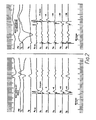
- the second type of nonsinus P wave is observed in supraventricular tachycardia.
- the pacemaker senses the P waves and will pace the ventricle at the rate of the P wave.
- the normal human AV node acts as a filter such that, in the adult, atrial impulses faster than 200 per minute usually will not be transmitted through the AV node to the ventricles. This is a natural event that a pacemaker can circumvent. For this reason, pacemakers have an "upper rate limit" where, regardless of atrial rate, the pacemaker will not transmit impulses to the ventricle above this rate.
- United States Patent 4,059,116 discloses a pacemaker that employs an upper rate limit. If supraventricular tachycardia could be distinguished from a normal rapid sinus tachycardia, the artificial "upper rate limit" could be eliminated.
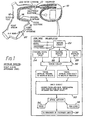
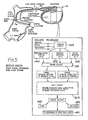
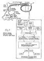
- proximal or proximal electrode pair shall mean an electrode or electrode pair positioned on the lead at a point farther from the end of the lead placed in the atrial electrical field than the distal electrode or distal electrode pair.
- Unipolar shall mean a mode of detecting voltage differences between two electrodes wherein one of the electrodes is on the lead placed in the electrical field created by atrial electrical activity and the other is an indifferent electrode outside the field.
- Bipolar shall mean a mode of detecting voltage differences between two electrodes wherein both electrodes are on the lead placed in the electrical field created by atrial electrical activity.
Landscapes
- Health & Medical Sciences (AREA)
- Cardiology (AREA)
- Heart & Thoracic Surgery (AREA)
- Engineering & Computer Science (AREA)
- Biomedical Technology (AREA)
- Nuclear Medicine, Radiotherapy & Molecular Imaging (AREA)
- Radiology & Medical Imaging (AREA)
- Life Sciences & Earth Sciences (AREA)
- Animal Behavior & Ethology (AREA)
- General Health & Medical Sciences (AREA)
- Public Health (AREA)
- Veterinary Medicine (AREA)
- Electrotherapy Devices (AREA)
Claims (15)
Applications Claiming Priority (2)
| Application Number | Priority Date | Filing Date | Title |
|---|---|---|---|
| US06/721,247 US4712554A (en) | 1985-04-08 | 1985-04-08 | Electronic system to distinguish between sinus and nonsinus atrial depolarizations which do not stimulate ventricular depolarizations in response to nonsinus atrial depolarizations |
| US721247 | 1985-04-08 |
Publications (2)
| Publication Number | Publication Date |
|---|---|
| EP0202748A1 EP0202748A1 (fr) | 1986-11-26 |
| EP0202748B1 true EP0202748B1 (fr) | 1990-07-18 |
Family
ID=24897149
Family Applications (1)
| Application Number | Title | Priority Date | Filing Date |
|---|---|---|---|
| EP86302556A Expired EP0202748B1 (fr) | 1985-04-08 | 1986-04-07 | Système électronique pour distinguer les dépolarisations sino et non sino-auriculaires |
Country Status (5)
| Country | Link |
|---|---|
| US (1) | US4712554A (fr) |
| EP (1) | EP0202748B1 (fr) |
| JP (1) | JPS6226079A (fr) |
| AU (1) | AU592556B2 (fr) |
| DE (1) | DE3672691D1 (fr) |
Cited By (1)
| Publication number | Priority date | Publication date | Assignee | Title |
|---|---|---|---|---|
| US9380953B2 (en) | 2014-01-29 | 2016-07-05 | Biosense Webster (Israel) Ltd. | Hybrid bipolar/unipolar detection of activation wavefront |
Families Citing this family (108)
| Publication number | Priority date | Publication date | Assignee | Title |
|---|---|---|---|---|
| US4917115A (en) * | 1988-07-11 | 1990-04-17 | Vitatron Medical B. V. | Pacing system and method for physiological stimulation of the heart utilizing Doppler means |
| JPH0321264A (ja) * | 1989-06-16 | 1991-01-30 | Inter Noba Kk | 体外型心臓ペースメーカ電極 |
| FR2669829B1 (fr) * | 1990-11-30 | 1996-09-13 | Ela Medical Sa | Procede de calcul de l'intervalle d'echappement a la fin duquel, il faut stimuler l'oreillette d'un cóoeur en cas d'absence de depolarisation. |
| US5193550A (en) * | 1990-11-30 | 1993-03-16 | Medtronic, Inc. | Method and apparatus for discriminating among normal and pathological tachyarrhythmias |
| US5282837A (en) * | 1991-04-12 | 1994-02-01 | Incontrol, Inc. | Atrial defibrillator and method |
| US5205283A (en) * | 1991-07-30 | 1993-04-27 | Medtronic, Inc. | Method and apparatus for tachyarrhythmia detection and treatment |
| US5257621A (en) * | 1991-08-27 | 1993-11-02 | Medtronic, Inc. | Apparatus for detection of and discrimination between tachycardia and fibrillation and for treatment of both |
| US5193535A (en) * | 1991-08-27 | 1993-03-16 | Medtronic, Inc. | Method and apparatus for discrimination of ventricular tachycardia from ventricular fibrillation and for treatment thereof |
| US5247930A (en) * | 1992-02-04 | 1993-09-28 | Vitatron Medical, B.V. | Dual chamber pacing system with dynamic physiological tracking and method of timing delivered stimulus for optimized synchronous pacing |
| US5275621A (en) * | 1992-04-13 | 1994-01-04 | Medtronic, Inc. | Method and apparatus for terminating tachycardia |
| US5366486A (en) * | 1992-06-25 | 1994-11-22 | Indiana University Foundation | Automatic fibrillation detector and defibrillator apparatus and method |
| US5243980A (en) * | 1992-06-30 | 1993-09-14 | Medtronic, Inc. | Method and apparatus for discrimination of ventricular and supraventricular tachycardia |
| SE9203171D0 (sv) * | 1992-10-28 | 1992-10-28 | Siemens Elema Ab | Anordning foer identifiering av atriell depolarisation |
| SE9301628D0 (sv) * | 1993-05-12 | 1993-05-12 | Siemens-Elema Ab | Foerfarande och anordning foer att bestaemma om elektriska signaler i ett hjaerta aer orsakade av en atriell depolarisation |
| US5447519A (en) * | 1994-03-19 | 1995-09-05 | Medtronic, Inc. | Method and apparatus for discrimination of monomorphic and polymorphic arrhythmias and for treatment thereof |
| ES2150676T5 (es) | 1995-06-23 | 2006-04-16 | Gyrus Medical Limited | Instrumento electroquirurgico. |
| US5607457A (en) * | 1995-09-29 | 1997-03-04 | Schueller; Hans | Pacemaker with evoked response detection by using differential sensing between two unipolar electrodes |
| US5782876A (en) * | 1996-04-15 | 1998-07-21 | Medtronic, Inc. | Method and apparatus using windows and an index value for identifying cardic arrhythmias |
| US6240313B1 (en) | 1999-04-19 | 2001-05-29 | Cardiac Pacemakers, Inc. | Cardiac rhythm management system with prevention of double counting of events |
| US6480741B1 (en) * | 1999-09-07 | 2002-11-12 | Cardiac Pacemakers, Inc. | Heart monitors with robust interval measurements |
| US6246908B1 (en) | 2000-02-04 | 2001-06-12 | Uab Research Foundation | Method and apparatus for rapidly predicting outcome of arrhythmia therapy |
| US6584352B2 (en) | 2000-12-27 | 2003-06-24 | Medtronic, Inc. | Leadless fully automatic pacemaker follow-up |
| US8391990B2 (en) | 2005-05-18 | 2013-03-05 | Cardiac Pacemakers, Inc. | Modular antitachyarrhythmia therapy system |
| DE102008020123A1 (de) | 2008-04-22 | 2009-10-29 | Biotronik Crm Patent Ag | Ventrikulärer Herzstimulator |
| US20150196769A1 (en) | 2014-01-10 | 2015-07-16 | Cardiac Pacemakers, Inc. | Methods and systems for improved communication between medical devices |
| AU2015204701B2 (en) | 2014-01-10 | 2018-03-15 | Cardiac Pacemakers, Inc. | Systems and methods for detecting cardiac arrhythmias |
| US9526909B2 (en) | 2014-08-28 | 2016-12-27 | Cardiac Pacemakers, Inc. | Medical device with triggered blanking period |
| JP2016063853A (ja) * | 2014-09-22 | 2016-04-28 | フクダ電子株式会社 | 電気生理学的検査装置 |
| ES2713231T3 (es) | 2015-02-06 | 2019-05-20 | Cardiac Pacemakers Inc | Sistemas para el suministro seguro de una terapia de estimulación eléctrica |
| EP3827877B1 (fr) | 2015-02-06 | 2024-06-19 | Cardiac Pacemakers, Inc. | Systèmes de traitement d'arythmies cardiaques |
| WO2016130477A2 (fr) | 2015-02-09 | 2016-08-18 | Cardiac Pacemakers, Inc. | Dispositif médical implantable comportant une étiquette d'identification radio-opaque |
| EP3265172B1 (fr) | 2015-03-04 | 2018-12-19 | Cardiac Pacemakers, Inc. | Systèmes de traitement d'arythmies cardiaques |
| CN107427222B (zh) | 2015-03-18 | 2021-02-09 | 心脏起搏器股份公司 | 使用链路质量评估的医疗设备系统中的通信 |
| US10050700B2 (en) | 2015-03-18 | 2018-08-14 | Cardiac Pacemakers, Inc. | Communications in a medical device system with temporal optimization |
| WO2017031347A1 (fr) | 2015-08-20 | 2017-02-23 | Cardiac Pacemakers, Inc. | Systèmes et procédés de communication entre des dispositifs médicaux |
| US9853743B2 (en) | 2015-08-20 | 2017-12-26 | Cardiac Pacemakers, Inc. | Systems and methods for communication between medical devices |
| US9956414B2 (en) | 2015-08-27 | 2018-05-01 | Cardiac Pacemakers, Inc. | Temporal configuration of a motion sensor in an implantable medical device |
| US9968787B2 (en) | 2015-08-27 | 2018-05-15 | Cardiac Pacemakers, Inc. | Spatial configuration of a motion sensor in an implantable medical device |
| US10137305B2 (en) | 2015-08-28 | 2018-11-27 | Cardiac Pacemakers, Inc. | Systems and methods for behaviorally responsive signal detection and therapy delivery |
| US10226631B2 (en) | 2015-08-28 | 2019-03-12 | Cardiac Pacemakers, Inc. | Systems and methods for infarct detection |
| WO2017040115A1 (fr) | 2015-08-28 | 2017-03-09 | Cardiac Pacemakers, Inc. | Système de détection de tamponnade |
| WO2017044389A1 (fr) | 2015-09-11 | 2017-03-16 | Cardiac Pacemakers, Inc. | Détection et confirmation d'arythmie |
| US10065041B2 (en) | 2015-10-08 | 2018-09-04 | Cardiac Pacemakers, Inc. | Devices and methods for adjusting pacing rates in an implantable medical device |
| JP6608063B2 (ja) | 2015-12-17 | 2019-11-20 | カーディアック ペースメイカーズ, インコーポレイテッド | 植込み型医療装置 |
| US10905886B2 (en) | 2015-12-28 | 2021-02-02 | Cardiac Pacemakers, Inc. | Implantable medical device for deployment across the atrioventricular septum |
| WO2017127548A1 (fr) | 2016-01-19 | 2017-07-27 | Cardiac Pacemakers, Inc. | Dispositifs permettant de recharger sans fil une batterie rechargeable d'un dispositif médical implantable |
| WO2017136548A1 (fr) | 2016-02-04 | 2017-08-10 | Cardiac Pacemakers, Inc. | Système de pose avec capteur de force pour dispositif cardiaque sans fil |
| US11116988B2 (en) | 2016-03-31 | 2021-09-14 | Cardiac Pacemakers, Inc. | Implantable medical device with rechargeable battery |
| US10328272B2 (en) | 2016-05-10 | 2019-06-25 | Cardiac Pacemakers, Inc. | Retrievability for implantable medical devices |
| US10668294B2 (en) | 2016-05-10 | 2020-06-02 | Cardiac Pacemakers, Inc. | Leadless cardiac pacemaker configured for over the wire delivery |
| JP6764956B2 (ja) | 2016-06-27 | 2020-10-07 | カーディアック ペースメイカーズ, インコーポレイテッド | 再同期ペーシング管理に皮下で感知されたp波を使用する心臓治療法システム |
| US11207527B2 (en) | 2016-07-06 | 2021-12-28 | Cardiac Pacemakers, Inc. | Method and system for determining an atrial contraction timing fiducial in a leadless cardiac pacemaker system |
| WO2018009392A1 (fr) | 2016-07-07 | 2018-01-11 | Cardiac Pacemakers, Inc. | Stimulateur cardiaque sans fil utilisant des mesures de pression pour la vérification de la capture de stimulation |
| CN109475743B (zh) | 2016-07-20 | 2022-09-02 | 心脏起搏器股份公司 | 在无引线心脏起搏器系统中利用心房收缩定时基准的系统 |
| WO2018035343A1 (fr) | 2016-08-19 | 2018-02-22 | Cardiac Pacemakers, Inc. | Dispositif médical implantable trans-septal |
| EP3503970B1 (fr) | 2016-08-24 | 2023-01-04 | Cardiac Pacemakers, Inc. | Resynchronisation cardiaque utilisant l'encouragement de la fusion pour la gestion de la synchronisation |
| CN109640809B (zh) | 2016-08-24 | 2021-08-17 | 心脏起搏器股份公司 | 使用p波到起搏定时的集成式多装置心脏再同步治疗 |
| US10758737B2 (en) | 2016-09-21 | 2020-09-01 | Cardiac Pacemakers, Inc. | Using sensor data from an intracardially implanted medical device to influence operation of an extracardially implantable cardioverter |
| WO2018057626A1 (fr) | 2016-09-21 | 2018-03-29 | Cardiac Pacemakers, Inc. | Moniteur cardiaque implantable |
| WO2018057318A1 (fr) | 2016-09-21 | 2018-03-29 | Cardiac Pacemakers, Inc. | Dispositif de stimulation sans fil muni d'un boîtier qui abrite des composants interne du dispositif de stimulation sans fil et fonctionne comme boîtier de batterie et borne d'une batterie interne |
| US10758724B2 (en) | 2016-10-27 | 2020-09-01 | Cardiac Pacemakers, Inc. | Implantable medical device delivery system with integrated sensor |
| AU2017350759B2 (en) | 2016-10-27 | 2019-10-17 | Cardiac Pacemakers, Inc. | Implantable medical device with pressure sensor |
| WO2018081237A1 (fr) | 2016-10-27 | 2018-05-03 | Cardiac Pacemakers, Inc. | Utilisation d'un dispositif séparé pour gérer l'énergie d'impulsion de stimulation d'un stimulateur cardiaque |
| US10413733B2 (en) | 2016-10-27 | 2019-09-17 | Cardiac Pacemakers, Inc. | Implantable medical device with gyroscope |
| WO2018081133A1 (fr) | 2016-10-27 | 2018-05-03 | Cardiac Pacemakers, Inc. | Dispositif médical implantable présentant un canal d'écoute à réglage de rendement |
| WO2018081275A1 (fr) | 2016-10-27 | 2018-05-03 | Cardiac Pacemakers, Inc. | Thérapie de resynchronisation cardiaque à dispositifs multiples avec des améliorations de synchronisation |
| US10434317B2 (en) | 2016-10-31 | 2019-10-08 | Cardiac Pacemakers, Inc. | Systems and methods for activity level pacing |
| EP3532157B1 (fr) | 2016-10-31 | 2020-08-26 | Cardiac Pacemakers, Inc. | Systèmes de stimulation de niveau d'activité |
| WO2018089311A1 (fr) | 2016-11-08 | 2018-05-17 | Cardiac Pacemakers, Inc | Dispositif médical implantable pour déploiement auriculaire |
| WO2018089308A1 (fr) | 2016-11-09 | 2018-05-17 | Cardiac Pacemakers, Inc. | Systèmes, dispositifs et procédés pour régler des paramètres d'impulsion de stimulation cardiaque pour un dispositif de stimulation cardiaque |
| US10639486B2 (en) | 2016-11-21 | 2020-05-05 | Cardiac Pacemakers, Inc. | Implantable medical device with recharge coil |
| US10881869B2 (en) | 2016-11-21 | 2021-01-05 | Cardiac Pacemakers, Inc. | Wireless re-charge of an implantable medical device |
| EP3541473B1 (fr) | 2016-11-21 | 2020-11-11 | Cardiac Pacemakers, Inc. | Stimulateur cardiaque sans sonde à communication multimodale |
| EP3541472B1 (fr) | 2016-11-21 | 2023-06-07 | Cardiac Pacemakers, Inc. | Dispositif médical implantable comportant un boîtier magnétiquement perméable et une bobine inductive placée autour du boîtier |
| CN109982746B (zh) | 2016-11-21 | 2023-04-04 | 心脏起搏器股份公司 | 提供心脏再同步治疗的无引线心脏起搏器 |
| US11207532B2 (en) | 2017-01-04 | 2021-12-28 | Cardiac Pacemakers, Inc. | Dynamic sensing updates using postural input in a multiple device cardiac rhythm management system |
| JP7000438B2 (ja) | 2017-01-26 | 2022-01-19 | カーディアック ペースメイカーズ, インコーポレイテッド | 冗長メッセージ送信を伴う人体デバイス通信 |
| CN110198759B (zh) | 2017-01-26 | 2023-08-11 | 心脏起搏器股份公司 | 具有可拆卸固定件的无引线可植入装置 |
| CN110234392B (zh) | 2017-01-26 | 2023-08-11 | 心脏起搏器股份公司 | 具有被包覆模制的组件的无引线装置 |
| US10905872B2 (en) | 2017-04-03 | 2021-02-02 | Cardiac Pacemakers, Inc. | Implantable medical device with a movable electrode biased toward an extended position |
| US10821288B2 (en) | 2017-04-03 | 2020-11-03 | Cardiac Pacemakers, Inc. | Cardiac pacemaker with pacing pulse energy adjustment based on sensed heart rate |
| WO2019036568A1 (fr) | 2017-08-18 | 2019-02-21 | Cardiac Pacemakers, Inc. | Dispositif médical implantable comprenant un concentrateur de flux et une bobine de réception disposée autour du concentrateur de flux |
| EP3668592B1 (fr) | 2017-08-18 | 2021-11-17 | Cardiac Pacemakers, Inc. | Dispositif médical implantable avec capteur de pression |
| JP6938778B2 (ja) | 2017-09-20 | 2021-09-22 | カーディアック ペースメイカーズ, インコーポレイテッド | 複数の作動モードを備えた移植式医療用装置 |
| US11185703B2 (en) | 2017-11-07 | 2021-11-30 | Cardiac Pacemakers, Inc. | Leadless cardiac pacemaker for bundle of his pacing |
| EP3717060B1 (fr) | 2017-12-01 | 2022-10-05 | Cardiac Pacemakers, Inc. | Stimulateur cardiaque sans fil à comportement réversible |
| WO2019108545A1 (fr) | 2017-12-01 | 2019-06-06 | Cardiac Pacemakers, Inc. | Procédés et systèmes pour détecter des repères de synchronisation de contraction auriculaire pendant un remplissage ventriculaire à partir d'un stimulateur cardiaque sans fil implanté de manière ventriculaire |
| EP3717063B1 (fr) | 2017-12-01 | 2023-12-27 | Cardiac Pacemakers, Inc. | Systèmes pour détecter des repères de synchronisation de contraction auriculaire et pour déterminer un intervalle cardiaque à partir d'un stimulateur cardiaque sans fil implanté de manière ventriculaire |
| EP3717059B1 (fr) | 2017-12-01 | 2024-11-20 | Cardiac Pacemakers, Inc. | Systèmes pour détecter des repères de synchronisation de contraction auriculaire dans une fenêtre de recherche à partir d'un stimulateur cardiaque sans fil implanté de manière ventriculaire |
| EP3735293B1 (fr) | 2018-01-04 | 2022-03-09 | Cardiac Pacemakers, Inc. | Stimulation double chambre sans communication battement à battement |
| US11529523B2 (en) | 2018-01-04 | 2022-12-20 | Cardiac Pacemakers, Inc. | Handheld bridge device for providing a communication bridge between an implanted medical device and a smartphone |
| US11058880B2 (en) | 2018-03-23 | 2021-07-13 | Medtronic, Inc. | VFA cardiac therapy for tachycardia |
| EP3768369A1 (fr) | 2018-03-23 | 2021-01-27 | Medtronic, Inc. | Thérapie cardiaque du ventricule vers l'atrium (vfa) synchrone atrioventriculaire (av) |
| JP2021518192A (ja) | 2018-03-23 | 2021-08-02 | メドトロニック,インコーポレイテッド | VfA心臓再同期治療 |
| EP3856331A1 (fr) | 2018-09-26 | 2021-08-04 | Medtronic, Inc. | Capture dans une thérapie cardiaque du ventricule à partir de l'oreillette |
| US11951313B2 (en) | 2018-11-17 | 2024-04-09 | Medtronic, Inc. | VFA delivery systems and methods |
| EP3897816B1 (fr) | 2018-12-21 | 2024-03-27 | Medtronic, Inc. | Systèmes de pose pour stimulation ventriculaire gauche |
| US11679265B2 (en) | 2019-02-14 | 2023-06-20 | Medtronic, Inc. | Lead-in-lead systems and methods for cardiac therapy |
| US11697025B2 (en) | 2019-03-29 | 2023-07-11 | Medtronic, Inc. | Cardiac conduction system capture |
| US11213676B2 (en) | 2019-04-01 | 2022-01-04 | Medtronic, Inc. | Delivery systems for VfA cardiac therapy |
| US11712188B2 (en) | 2019-05-07 | 2023-08-01 | Medtronic, Inc. | Posterior left bundle branch engagement |
| US11305127B2 (en) | 2019-08-26 | 2022-04-19 | Medtronic Inc. | VfA delivery and implant region detection |
| US11813466B2 (en) | 2020-01-27 | 2023-11-14 | Medtronic, Inc. | Atrioventricular nodal stimulation |
| US12543992B2 (en) | 2020-03-30 | 2026-02-10 | Medtronic, Inc. | Pacing efficacy determination using a representative morphology of external cardiac signals |
| US11911168B2 (en) | 2020-04-03 | 2024-02-27 | Medtronic, Inc. | Cardiac conduction system therapy benefit determination |
| US12605103B2 (en) | 2020-05-21 | 2026-04-21 | Medtronic, Inc. | QRS detection and bracketing |
| US11813464B2 (en) | 2020-07-31 | 2023-11-14 | Medtronic, Inc. | Cardiac conduction system evaluation |
| US12465770B2 (en) | 2020-07-31 | 2025-11-11 | Medtronic, Inc. | Coronary sinus conduction system pacing and delivery |
Family Cites Families (24)
| Publication number | Priority date | Publication date | Assignee | Title |
|---|---|---|---|---|
| US3138151A (en) * | 1962-06-11 | 1964-06-23 | Robert L Chapman | Detector and alarm ventricular impulses |
| US3385289A (en) * | 1963-11-12 | 1968-05-28 | John D. Lawson | Apparatus and method for detecting, comparing and recording heart valve muscular activities |
| GB1424355A (en) * | 1972-03-11 | 1976-02-11 | Kent Cambridge Medical Ltd | Cardiac pacers |
| US3832994A (en) * | 1972-04-21 | 1974-09-03 | Mediscience Corp | Cardiac monitor |
| US3823708A (en) * | 1972-06-08 | 1974-07-16 | Cardiodynamics | Tachycardia detector |
| US4059116A (en) * | 1974-12-09 | 1977-11-22 | Medtronic, Inc. | Synchronous pacemaker with upper rate stabilization and method of use |
| US4202340A (en) * | 1975-09-30 | 1980-05-13 | Mieczyslaw Mirowski | Method and apparatus for monitoring heart activity, detecting abnormalities, and cardioverting a malfunctioning heart |
| US4088140A (en) * | 1976-06-18 | 1978-05-09 | Medtronic, Inc. | Demand anti-arrhythmia pacemaker |
| US4091817A (en) * | 1976-09-27 | 1978-05-30 | American Optical Corporation | P-Wave control, R-wave inhibited ventricular stimulation device |
| US4403614A (en) * | 1979-07-19 | 1983-09-13 | Medtronic, Inc. | Implantable cardioverter |
| US4289134A (en) * | 1979-07-23 | 1981-09-15 | Electro-Catheter Corporation | Tripolar catheter apparatus |
| US4365639A (en) * | 1980-02-07 | 1982-12-28 | Applied Cardiac Electrophysiology | Catheter, cardiac pacemaker and method of pacing |
| US4303075A (en) * | 1980-02-11 | 1981-12-01 | Mieczyslaw Mirowski | Method and apparatus for maximizing stroke volume through atrioventricular pacing using implanted cardioverter/pacer |
| US4343311A (en) * | 1980-04-30 | 1982-08-10 | Medtronic, Inc. | Atrial refractory control for R-wave rejection in pacemakers |
| US4432362A (en) * | 1980-05-27 | 1984-02-21 | Cordis Corporation | Atrial-based, atrial-ventricular sequential cardiac pacer |
| US4387717A (en) * | 1980-10-03 | 1983-06-14 | Research Corporation | Pacer internal cardiac electrogram sensing system |
| US4421116A (en) * | 1980-10-14 | 1983-12-20 | Medtronic, Inc. | Heart pacemaker with separate A-V intervals for atrial synchronous and atrial-ventricular sequential pacing modes |
| US4390021A (en) * | 1981-03-23 | 1983-06-28 | Telectronics Pty. Ltd. | Two pulse tachycardia control pacer |
| US4452248A (en) * | 1981-10-13 | 1984-06-05 | Keller Jr J Walter | Bidirectional pacemaker |
| US4458691A (en) * | 1982-02-11 | 1984-07-10 | Arrhythmia Research Technology, Inc. | System and method for predicting ventricular tachycardia by adaptive high pass filter |
| GB2119255A (en) * | 1982-04-12 | 1983-11-16 | Telectronics Pty Ltd | Three-electrode pacing/sensing heart pacer |
| US4493325A (en) * | 1982-05-03 | 1985-01-15 | Medtronic, Inc. | Tachyarrhythmia pacer |
| US4549548A (en) * | 1983-09-14 | 1985-10-29 | Vitafin N.V. | Pacemaker system with automatic event-programmed switching between unipolar and bipolar operation |
| US4543963A (en) * | 1983-11-22 | 1985-10-01 | Gessman Lawrence J | Method and apparatus for differentiating antegrade from retrograde P-waves and for preventing pacemaker generated tachycardia |
-
1985
- 1985-04-08 US US06/721,247 patent/US4712554A/en not_active Expired - Fee Related
-
1986
- 1986-04-07 EP EP86302556A patent/EP0202748B1/fr not_active Expired
- 1986-04-07 DE DE8686302556T patent/DE3672691D1/de not_active Expired - Lifetime
- 1986-04-08 AU AU55756/86A patent/AU592556B2/en not_active Ceased
- 1986-04-08 JP JP61081969A patent/JPS6226079A/ja active Pending
Cited By (1)
| Publication number | Priority date | Publication date | Assignee | Title |
|---|---|---|---|---|
| US9380953B2 (en) | 2014-01-29 | 2016-07-05 | Biosense Webster (Israel) Ltd. | Hybrid bipolar/unipolar detection of activation wavefront |
Also Published As
| Publication number | Publication date |
|---|---|
| DE3672691D1 (de) | 1990-08-23 |
| AU592556B2 (en) | 1990-01-18 |
| AU5575686A (en) | 1986-10-16 |
| EP0202748A1 (fr) | 1986-11-26 |
| JPS6226079A (ja) | 1987-02-04 |
| US4712554A (en) | 1987-12-15 |
Similar Documents
| Publication | Publication Date | Title |
|---|---|---|
| EP0202748B1 (fr) | Système électronique pour distinguer les dépolarisations sino et non sino-auriculaires | |
| US5857977A (en) | Method and apparatus for separation of ventricular tachycardia from ventricular fibrillation for implantable cardioverter defibrillators | |
| EP0647150B1 (fr) | Appareil permettant de distinguer la tachycardie ventriculaire de la tachycardie supraventriculaire et appareil permettant de distinguer un rythme cardiaque rapide d'origine sinusale d'un rythme cardiaque rapide d'origine non sinusale | |
| EP3431135B1 (fr) | Système pour detection automatique du seuil de capture et stimulation du faisceau de his associée | |
| US4354497A (en) | Cardiac depolarization detection apparatus | |
| US5109842A (en) | Implantable tachyarrhythmia control system having a patch electrode with an integrated cardiac activity system | |
| US9061156B2 (en) | Automatic selection of stimulation chamber for ventricular resynchronization therapy | |
| US6263242B1 (en) | Apparatus and method for timing the delivery of non-excitatory ETC signals to a heart | |
| US7437192B2 (en) | System and method for detecting heart failure and pulmonary edema based on ventricular end-diastolic pressure using an implantable medical device | |
| US6526317B2 (en) | System and method for treating atrial arrhythmias | |
| WO1998005254A9 (fr) | Methode et appareil permettant de distinguer une tachycardie ventriculaire d'une fibrillation ventriculaire, pour defibrillateurs implantables a synchronisation automatique | |
| EP3877044A1 (fr) | Système de stimulation cardiaque avec optimisation automatisée de la stimulation du faisceau de his pour une thérapie de resynchronisation cardiaque | |
| US7203535B1 (en) | System and method for classifying tachycardia arrhythmias having 1:1 atrial-to-ventricular rhythms | |
| US6980861B1 (en) | Implantable medical device and method for detecting cardiac events without using of refractory or blanking periods | |
| US7881792B1 (en) | Methods and systems for detecting the presence of T-wave alternans | |
| US7844333B1 (en) | Pacing therapy for transient ischemia treatment | |
| Goldreyer et al. | Orthogonal electrogram sensing | |
| US9220434B2 (en) | Systems and methods for selectively updating cardiac morphology discrimination templates for use with implantable medical devices | |
| US7756571B1 (en) | Methods and systems for detecting the presence of T-wave alternans | |
| CA1192263A (fr) | Methode et sonde pour capter les signaux intracardiaques | |
| RUBIN et al. | The electrocardiographic recognition of pacemaker function and failure | |
| Mitchell et al. | Recordings of basal ventricular preexcitation from electrode catheters in patients with accessory atrioventricular connections. | |
| Kirk | Basic principles of pacing | |
| Nalos et al. | Benefits of intracardiac electrograms and programmable sensing polarity in preventing pacemaker inhibition due to spurious screw‐in lead signals | |
| Zaidan | Care of the Pacemaker Patient Undergoing General Surgery |
Legal Events
| Date | Code | Title | Description |
|---|---|---|---|
| PUAI | Public reference made under article 153(3) epc to a published international application that has entered the european phase |
Free format text: ORIGINAL CODE: 0009012 |
|
| AK | Designated contracting states |
Kind code of ref document: A1 Designated state(s): CH DE FR GB IT LI NL SE |
|
| 17P | Request for examination filed |
Effective date: 19870520 |
|
| 17Q | First examination report despatched |
Effective date: 19890330 |
|
| GRAA | (expected) grant |
Free format text: ORIGINAL CODE: 0009210 |
|
| AK | Designated contracting states |
Kind code of ref document: B1 Designated state(s): CH DE FR GB IT LI NL SE |
|
| ITF | It: translation for a ep patent filed | ||
| REF | Corresponds to: |
Ref document number: 3672691 Country of ref document: DE Date of ref document: 19900823 |
|
| ET | Fr: translation filed | ||
| PG25 | Lapsed in a contracting state [announced via postgrant information from national office to epo] |
Ref country code: GB Effective date: 19910407 |
|
| PG25 | Lapsed in a contracting state [announced via postgrant information from national office to epo] |
Ref country code: SE Effective date: 19910408 |
|
| PG25 | Lapsed in a contracting state [announced via postgrant information from national office to epo] |
Ref country code: LI Effective date: 19910430 Ref country code: CH Effective date: 19910430 |
|
| PLBE | No opposition filed within time limit |
Free format text: ORIGINAL CODE: 0009261 |
|
| STAA | Information on the status of an ep patent application or granted ep patent |
Free format text: STATUS: NO OPPOSITION FILED WITHIN TIME LIMIT |
|
| 26N | No opposition filed | ||
| PG25 | Lapsed in a contracting state [announced via postgrant information from national office to epo] |
Ref country code: NL Effective date: 19911101 |
|
| GBPC | Gb: european patent ceased through non-payment of renewal fee | ||
| NLV4 | Nl: lapsed or anulled due to non-payment of the annual fee | ||
| PG25 | Lapsed in a contracting state [announced via postgrant information from national office to epo] |
Ref country code: FR Effective date: 19911230 |
|
| REG | Reference to a national code |
Ref country code: CH Ref legal event code: PL |
|
| PG25 | Lapsed in a contracting state [announced via postgrant information from national office to epo] |
Ref country code: DE Effective date: 19920201 |
|
| REG | Reference to a national code |
Ref country code: FR Ref legal event code: ST |
|
| EUG | Se: european patent has lapsed |
Ref document number: 86302556.5 Effective date: 19911108 |
|
| PG25 | Lapsed in a contracting state [announced via postgrant information from national office to epo] |
Ref country code: IT Free format text: LAPSE BECAUSE OF NON-PAYMENT OF DUE FEES;WARNING: LAPSES OF ITALIAN PATENTS WITH EFFECTIVE DATE BEFORE 2007 MAY HAVE OCCURRED AT ANY TIME BEFORE 2007. THE CORRECT EFFECTIVE DATE MAY BE DIFFERENT FROM THE ONE RECORDED. Effective date: 20050407 |