EP0202748B1 - Electronic system to distinguish between sinus and nonsinus atrial depolarizations - Google Patents
Electronic system to distinguish between sinus and nonsinus atrial depolarizations Download PDFInfo
- Publication number
- EP0202748B1 EP0202748B1 EP86302556A EP86302556A EP0202748B1 EP 0202748 B1 EP0202748 B1 EP 0202748B1 EP 86302556 A EP86302556 A EP 86302556A EP 86302556 A EP86302556 A EP 86302556A EP 0202748 B1 EP0202748 B1 EP 0202748B1
- Authority
- EP
- European Patent Office
- Prior art keywords
- lead
- electrodes
- electrode
- attached
- pair
- Prior art date
- Legal status (The legal status is an assumption and is not a legal conclusion. Google has not performed a legal analysis and makes no representation as to the accuracy of the status listed.)
- Expired
Links
- 230000004213 regulation of atrial cardiomyocyte membrane depolarization Effects 0.000 title claims description 33
- 210000005245 right atrium Anatomy 0.000 claims description 39
- 210000005247 right atrial appendage Anatomy 0.000 claims description 24
- 230000002861 ventricular Effects 0.000 claims description 14
- 230000034225 regulation of ventricular cardiomyocyte membrane depolarization Effects 0.000 claims description 6
- 230000004936 stimulating effect Effects 0.000 claims description 6
- 230000004044 response Effects 0.000 claims description 3
- 230000001746 atrial effect Effects 0.000 description 66
- 230000000694 effects Effects 0.000 description 28
- 210000002837 heart atrium Anatomy 0.000 description 28
- 230000004913 activation Effects 0.000 description 23
- 230000033764 rhythmic process Effects 0.000 description 15
- 230000008602 contraction Effects 0.000 description 11
- 230000000747 cardiac effect Effects 0.000 description 9
- 238000010586 diagram Methods 0.000 description 7
- 230000002123 temporal effect Effects 0.000 description 7
- 210000001992 atrioventricular node Anatomy 0.000 description 6
- 230000005684 electric field Effects 0.000 description 6
- 230000028161 membrane depolarization Effects 0.000 description 5
- 208000003734 Supraventricular Tachycardia Diseases 0.000 description 4
- 238000000034 method Methods 0.000 description 4
- 208000009729 Ventricular Premature Complexes Diseases 0.000 description 3
- 239000008280 blood Substances 0.000 description 3
- 210000004369 blood Anatomy 0.000 description 3
- 206010053486 Pacemaker generated arrhythmia Diseases 0.000 description 2
- 206010047289 Ventricular extrasystoles Diseases 0.000 description 2
- 201000010099 disease Diseases 0.000 description 2
- 208000037265 diseases, disorders, signs and symptoms Diseases 0.000 description 2
- 239000012528 membrane Substances 0.000 description 2
- 210000003205 muscle Anatomy 0.000 description 2
- 210000001013 sinoatrial node Anatomy 0.000 description 2
- 230000002269 spontaneous effect Effects 0.000 description 2
- 206010003671 Atrioventricular Block Diseases 0.000 description 1
- 208000007888 Sinus Tachycardia Diseases 0.000 description 1
- 206010042600 Supraventricular arrhythmias Diseases 0.000 description 1
- 230000002159 abnormal effect Effects 0.000 description 1
- 230000005856 abnormality Effects 0.000 description 1
- 238000013459 approach Methods 0.000 description 1
- 230000017531 blood circulation Effects 0.000 description 1
- 238000013461 design Methods 0.000 description 1
- 230000009977 dual effect Effects 0.000 description 1
- 230000009177 electrical depolarization Effects 0.000 description 1
- 239000000835 fiber Substances 0.000 description 1
- 230000036449 good health Effects 0.000 description 1
- WABPQHHGFIMREM-UHFFFAOYSA-N lead(0) Chemical compound [Pb] WABPQHHGFIMREM-UHFFFAOYSA-N 0.000 description 1
- 238000012423 maintenance Methods 0.000 description 1
- 239000002184 metal Substances 0.000 description 1
- 210000000663 muscle cell Anatomy 0.000 description 1
- 210000004165 myocardium Anatomy 0.000 description 1
- 230000000661 pacemaking effect Effects 0.000 description 1
- 230000002250 progressing effect Effects 0.000 description 1
- 230000002685 pulmonary effect Effects 0.000 description 1
- 238000000718 qrs complex Methods 0.000 description 1
- 230000002441 reversible effect Effects 0.000 description 1
- 210000005241 right ventricle Anatomy 0.000 description 1
- 238000000926 separation method Methods 0.000 description 1
- 230000007480 spreading Effects 0.000 description 1
- 230000000638 stimulation Effects 0.000 description 1
- 230000009885 systemic effect Effects 0.000 description 1
- 238000012360 testing method Methods 0.000 description 1
- 210000001519 tissue Anatomy 0.000 description 1
- 238000011277 treatment modality Methods 0.000 description 1
- 230000002792 vascular Effects 0.000 description 1
- XLYOFNOQVPJJNP-UHFFFAOYSA-N water Substances O XLYOFNOQVPJJNP-UHFFFAOYSA-N 0.000 description 1
Images


Classifications
-
- A—HUMAN NECESSITIES
- A61—MEDICAL OR VETERINARY SCIENCE; HYGIENE
- A61N—ELECTROTHERAPY; MAGNETOTHERAPY; RADIATION THERAPY; ULTRASOUND THERAPY
- A61N1/00—Electrotherapy; Circuits therefor
- A61N1/18—Applying electric currents by contact electrodes
- A61N1/32—Applying electric currents by contact electrodes alternating or intermittent currents
- A61N1/36—Applying electric currents by contact electrodes alternating or intermittent currents for stimulation
- A61N1/362—Heart stimulators
- A61N1/3621—Heart stimulators for treating or preventing abnormally high heart rate
- A61N1/3622—Heart stimulators for treating or preventing abnormally high heart rate comprising two or more electrodes co-operating with different heart regions
Definitions
- the second type of nonsinus P wave is observed in supraventricular tachycardia.
- the pacemaker senses the P waves and will pace the ventricle at the rate of the P wave.
- the normal human AV node acts as a filter such that, in the adult, atrial impulses faster than 200 per minute usually will not be transmitted through the AV node to the ventricles. This is a natural event that a pacemaker can circumvent. For this reason, pacemakers have an "upper rate limit" where, regardless of atrial rate, the pacemaker will not transmit impulses to the ventricle above this rate.
- United States Patent 4,059,116 discloses a pacemaker that employs an upper rate limit. If supraventricular tachycardia could be distinguished from a normal rapid sinus tachycardia, the artificial "upper rate limit" could be eliminated.
- proximal or proximal electrode pair shall mean an electrode or electrode pair positioned on the lead at a point farther from the end of the lead placed in the atrial electrical field than the distal electrode or distal electrode pair.
- Unipolar shall mean a mode of detecting voltage differences between two electrodes wherein one of the electrodes is on the lead placed in the electrical field created by atrial electrical activity and the other is an indifferent electrode outside the field.
- Bipolar shall mean a mode of detecting voltage differences between two electrodes wherein both electrodes are on the lead placed in the electrical field created by atrial electrical activity.
Landscapes
- Health & Medical Sciences (AREA)
- Cardiology (AREA)
- Heart & Thoracic Surgery (AREA)
- Engineering & Computer Science (AREA)
- Biomedical Technology (AREA)
- Nuclear Medicine, Radiotherapy & Molecular Imaging (AREA)
- Radiology & Medical Imaging (AREA)
- Life Sciences & Earth Sciences (AREA)
- Animal Behavior & Ethology (AREA)
- General Health & Medical Sciences (AREA)
- Public Health (AREA)
- Veterinary Medicine (AREA)
- Electrotherapy Devices (AREA)
Description
- The present invention relates to an electronic system that enables distinguishing between sinus and nonsinus atrial depolarizations which, when incorporated into cardiac pacemakers, prevents the pacemakers from stimulating ventricular contractions following nonsinus atrial depolarizations.
- Contraction of cardiac muscle, like all muscle tissue, occurs in response to changes in the electrical potential of the membranes of the muscle cells. When the changes in membrane electrical potentials are recorded and plotted against time, a pattern characteristic of sinus cardiac depolarization is produced. First, a P wave corresponding to depolarization of the atria is seen. A fraction of a second later, a QRS complex corresponding to ventricular activation is observed.
- In normal sinus cardiac activation, the wave of electrical depolarization begins in the high right atrium in the sinoatrial (SA) node. From there the wave spreads over the atria in a pattern resembling spreading of waves created by throwing a pebble into water. Located near the juncture of the right atrium and right ventricle is the atrioventricular (AV) node. The wave of depolarization that has spread over the atria converges at the AV node and from there is conducted via specialized conduction fibers to the ventricles resulting in ventricular activation. The delay inherent in conduction from the atria to the ventricles allows sufficient time for atrial contraction to fill the ventricles, and thus maximizes the efficiency of each ventricular contraction.
- Because the sequence of atrial and ventricular depolarization observed in normal sinus rhythm optimizes blood flow with each ventricular contraction, maintenance of this sequence is required for continued good health. In a number of disease states, however, normal sinus rhythm is disrupted. For example, when premature ventricular contractions occur, the wave of depolarization begins in a ventricle causing the ventricles to contract before they have been filled with blood from the atrial contraction. If premature ventricular contractions occur too frequently, the reduced amount of blood pumped can be life threatening. Another common abnormal cardiac rhythm is seen when normal conduction from the atria to the ventricles is partially or totally blocked. In these patients, the wave of depolarization begins in the SA node as in normal sinus rhythm, but the wave is not conducted to the ventricles and thus fails to result in the blood being pumped through the pulmonary and systemic vascular systems.
- Electronic pacemakers have proved a very effective and reliable treatment modality in patients whose normal sinus rhythms have been disrupted by disease. Many pacemakers in current use that are implanted are dual chambered devices that are capable of sensing and pacing in the atrium and the ventricle. These pacemakers are called "universal" since they can perform almost any function. When the patient's atrial rate falls below a predetermined level, the pacemaker paces the atrium. After a delay sufficient to permit conduction from the atrium to the ventricle, if conduction has not occurred, the pacemaker also paces the ventricle. In many cases the atrial rate is sufficient, however, there is a lack of appropriate AV conduction. In these patients, the pacemaker will sense the patient's own atrial P wave and then pace the ventricle after the P wave.
- One of the greatest difficulties in modern pace- making is that current pacemakers cannot distinguish between sinus P waves and nonsinus P waves. Two major types of nonsinus P waves exist. The first is the "retrograde" P wave. This can occur any time the ventricle is paced by a pacemaker or a premature ventricular contraction occurs with conduction of the ventricular impulse retrogradely to the atrium (retrograde conduction can exist even in a patient with complete antegrade AV block). In this instance, the pacemaker senses the retrograde P wave and responds as though it were a normal sinus P wave. Since the pacemaker is programmed to pace the ventricle after every sensed P wave, an "endless loop" type of pacemaker mediated tachycardia can result. Every time the pacemaker paces the ventricle, it conducts retrogradely to the atrium, is sensed by the pacemaker, and then the pacemaker undesirably paces the ventricle.
- Many artificial adjustments are made in current pacemakers in an attempt to circumvent "endless loop" pacemaker mediated tachycardia. The majority of these attempts involve creation of a time during the cardiac cycle when the pacemaker does not sense in the atrium. United States Patent 4,343,311 provides an example of this approach. The disadvantages occasioned in creating a time when the pacemaker does not sense in the atrium include patient-to-patient variability in the time delay required, the lack of atrial sensing throughout the entire cardiac cycle, and restricting the upper limit that the pacemaker can pace the ventricle.
- The second type of nonsinus P wave is observed in supraventricular tachycardia. In the vast majority of cases of supraventricular tachycardia, the pacemaker senses the P waves and will pace the ventricle at the rate of the P wave. The normal human AV node acts as a filter such that, in the adult, atrial impulses faster than 200 per minute usually will not be transmitted through the AV node to the ventricles. This is a natural event that a pacemaker can circumvent. For this reason, pacemakers have an "upper rate limit" where, regardless of atrial rate, the pacemaker will not transmit impulses to the ventricle above this rate. United States Patent 4,059,116 discloses a pacemaker that employs an upper rate limit. If supraventricular tachycardia could be distinguished from a normal rapid sinus tachycardia, the artificial "upper rate limit" could be eliminated.
- In "retrograde" P waves, the sequence of atrial activiation differs from sinus P waves. In sinus P waves, the atria are activated from the SA node and activation spreads from the high atrium to the low atrium. In "retrograde" P waves, the atria are activated in the reverse direction from low atrium to high atrium. In over 90 percent of supraventricular - tachycardias, the atria are activated in a different sequence from sinus rhythm. Therefore, sinus and nonsinus P waves can be distinguished by determining the atrial activation sequence.
- In currently used pacemakers, sensing of the atrium is either "unipolar" or "bipolar." In unipolar sensing, there is a single electrode at the tip of the pacemaker lead. This lead usually is placed in the right atrial appendage (RAA) and uses the pacemaker generator as the indifferent electrode. In the bipolar configuration two electrodes are placed approximately 20 mm apart at the end of the lead which also is paced in the right atrial appendage. None of the pacemakers in current use possess a design that enables determining the atrial activation sequence to distinguish between sinus and nonsinus P waves.
- The present invention is directed to apparatuses that distinguish between sinus and nonsinus atrial depolarizations by determining the direction of atrial activation. The invention includes cardiac pacemakers designed to distinguish between sinus and nonsinus atrial depolarizations, which pacemakers stimulate ventricular contractions only when the immediately preceding atrial depolarization was a pacemaker stimulated or spontaneous sinus atrial contraction. According to the present invention, the direction of atrial depolarization is determined by detecting atrial electrical activity at two or more points in the atrium, one point closer to the ventricle than the other. The temporal relationship of the times at which atrial electrical activity is detected at the two points then is compared with the temporal relationship characteristic of sinus atrial depolarizations to distinguish sinus from nonsinus atrial depolarizations.
- Accordingly, it is an object of the present invention to provide an apparatus for detecting electrical activity at two points in the atrium and comparing the temporal relationship of the activity so detected to distinguish between sinus and nonsinus atrial depolarizations.
- A further object of the present invention is to provide cardiac pacemakers that distinguish between sinus and nonsinus atrial depolarizations and that do not stimulate ventricular depolarizations when the immediately preceding atrial depolarization was a nonsinus atrial depolarization.
- Other and further objects, features, and advantages will be apparent from the following description of the presently preferred embodiments of the invention, given for the purpose of disclosure when taken in conjunction with the accompanying drawings.
-
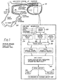
- Figure 1 is a diagram of a pacemaker having a two electrode lead positioned in the right atrial appendage and shows the electronic circuitry of the pacemaker.
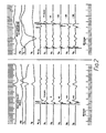
- Figure 2 is a strip chart recording showing the temporal relationship of atrial electrical activity recorded by unipolar sensing and bipolar sensing using the apparatus of Figure 1.
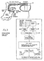
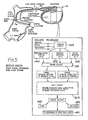
- Figure 3 is a diagram of a pacemaker having a lead with two pairs of electrodes positioned in the right atrial appendage and shows the electronic circuitry of the pacemaker.
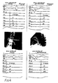
- Figure 4 is a strip chart recording showing the temporal relationships of atrial electrical activity detected by unipolar and bipolar sensing of sinus and retrograde atrial electrical activities using a lead with two electrodes positioned in the right atrial appendage and bipolar sensing using a lead with two pairs of electrodes positioned in the right atrial appendage.
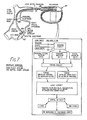
- Figure 5 is a diagram of a pacemaker having a two electrode lead positioned with one electrode in the right atrial appendage and one electrode in the high right atrium and shows the electronic circuitry of the pacemaker.
- Figure 6 is a strip chart recording showing the temporal relationship of atrial electrical activity detected by unipolar and bipolar sensing of sinus and retrograde atrial electrical activity using the apparatus of Figure 5.
- Figure 7 is a diagram of a pacemaker having a two electrode lead positioned so that one electrode is in the low septal right atrium and the other is in the high right atrium and shows the electronic circuitry of the pacemaker.
- Figure 8 is a diagram of a pacemaker having a lead with two pairs of electrodes positioned so that one pair of electrodes is in the low septal right atrium and the other is in the high right atrium.
- Figure 9 is a strip chart recording showing the temporal relationship of atrial electrical activity detected by unipolar and bipolar sensing of sinus and retrograde atrial electrical activity using a two electrode lead positioned so that one electrode is in the low septal right atrium and the other is in the high right atrium and by bipolar sensing using a two paired electrode lead positioned so that one pair of electrodes is in the low septal right atrium and the other pair of electrodes is in the high right atrium.
- The pattern of electrical activity associated with sinus atrial depolarizations differs from that associated with nonsinus atrial depolarizations such as occur following retrograde conduction of electrical activity beginning in the ventricles and that which are observed in supraventricular arrhythmias. Recording atrial electrical activity on a strip chart recorder provides a convenient method for visualizing these differences. Both the morphology (the shape of the electrogram) and the timing of the electrogram are useful parameters to distinguish sinus and nonsinus atrial depolarizations.
- As described below, the present inventor has devised several apparatuses and procedures for detecting and utilizing differences in the patterns of atrial electrical activity to distinguish sinus from nonsinus atrial depolarizations. In each of the below examples, an electric lead having at least two or two pairs of electrodes attached near one end is employed to detect atrial electrical activity. The end of the lead bearing the electrodes is positioned within the electrical field created by electrical activity in the atrium. The terms distal electrode or distal electrode pair shall mean the electrode or electrode pair positioned on the lead closest to the end of the lead implanted in the atrial electrical field. The terms proximal or proximal electrode pair shall mean an electrode or electrode pair positioned on the lead at a point farther from the end of the lead placed in the atrial electrical field than the distal electrode or distal electrode pair. Unipolar shall mean a mode of detecting voltage differences between two electrodes wherein one of the electrodes is on the lead placed in the electrical field created by atrial electrical activity and the other is an indifferent electrode outside the field. Bipolar shall mean a mode of detecting voltage differences between two electrodes wherein both electrodes are on the lead placed in the electrical field created by atrial electrical activity.
- Referring now to Figure 1, a
pacemaker 10 with a two electrode sensing/pacing lead 12 is shown with the lead positioned in the right atrial appendage (RAA). Presently, the right atrial appendage is the most common site for placement of pacemaker leads 12. In the "unipolar" configuration, a single electrode close to the site of electrical activation (the electrode on the end of this lead) is compared with a distant "indifferent" electrode. In current pacing, the indifferent electrode is actually the casing of the pacemaker. Therefore, in unipolar sensing, the electrical potential is sensed between two electrodes; one is within the atrial electrical field and the other is distant from this field. In this example, which is the least complicated embodiment of the present invention, unipolar sensing in the right atrial appendage is utilized. Asingle pacemaker lead 12 having twoelectrodes electrode 16 is at the distal tip of the lead and the moreproximal electrode 14 is several millimeters to centimeters, such as 20 to 40 mm, back from the tip. As is shown in Figure 1, using thislead 12, there are three inputs to the pacemaker: unipolar from thedistal electrode 16, unipolar from theproximal electrode 14, and bipolar between the electrodes. - The diagram of the atrium included in Figure 1 shows the sinus node 18 (pacemaker of the heart) and the
AV node 20 which is the conduction tissue that transmits electrical impulses from the atrium to the ventricle or that transmits impulses retrogradely from the ventricle to the atrium. Activation of the atrium in sinus rhythm begins at thesinus node 18. In contrast, retrograde activation of the atrium begins at theAV node 20. In the unipolar electrode configuration, the proximal 14 and distal 16 electrodes are connected to alead wire 12 which is connected to the pacemaker. The indifferent electrode is sensed from the pacemaker covering. As shown in Figure 1, the input goes through a standard pre-amplifier and then to aconventional sensing circuit 22. There are three outputs of the sensing circuit: a bipolar electrogram comparing the potential between the proximal anddistal electrodes 24, aunipolar electrogram 26 from the proximal electrode where the potential between the proximal electrode and the indifferent electrode is displayed, and finally theunipolar electrogram 28 from the distal electrode where the potential between the distal electrode and the indifferent electrode is displayed. These electrodes then input into theconventional timing circuit 30, and a time difference in milliseconds is calculated. For these inputs, there are only two times that need be calculated: 1) the timing from the unipolar proximal electrogram to the unipolar distal electrogram, and 2) the timing from the bipolar (proximal-distal electrogram) to the unipolar-proximal electrogram). The bipolar to unipolar distal time is not calculated because it is derived from the other two calculated times. - Once the timing of the atrial electrograms has been calculated above, it is used by a
suitable logic circuit 32 to determine whether the atrial activation is sinus or nonsinus. There are two methods available for making this determination. First, if the data are found to be conclusive that, in all patients, there is a consistent numerical difference in these two timings between sinus and nonsinus atrial electrograms, then this numerical difference will be programmed into the pacemaker logic circuit. For example, if in all patients in sinus rhythm the proximal unipolar electrogram is more than 10 milliseconds after the bipolar electrogram and in retrograde activation, the unipolar proximal electrogram is more than 10 milliseconds before the bipolar electrogram, these parameters will be programmed into the pacemaker, and the pacemaker will use these criteria to distinguish between sinus and nonsinus atrial electrograms. On the other hand, it is possible that some patients may have unique differences between their own sinus and nonsinus P waves. In these cases, the pacemaker will be programmed with the times unique to the patients in whom the pacemaker is to be used. In these patients, the pacemaker will use the times unique to the patients to distinguish betweensinus 34 andnonsinus 36 atrial electrograms. Returning to Figure 1, once the pacemaker distinguishes betweensinus 34 andnonsinus 36 atrial activity, this information is fed to the remainder of thepacemaker logic 38 which includes conventional ventricular stimulating circuitry and thepacemaker 10 stimulates a ventricular depolarization only when the immediately preceding atrial contraction was a spontaneous or pacemaker stimulated sinus atrial depolarization. - Testing in more than ten patients has demonstrated that comparing unipolar atrial electrograms to bipolar atrial electrograms provides a reliable method for distinguishing between sinus and nonsinus atrial depolarizations. Figure 2 demonstrates how strip chart recording of atrial electrograms is used to distinguish between sinus and nonsinus atrial depolarizations. Presently, standard intracardiac electrophysiologic catheters have been used to determine activation sequence. These catheters have between four and ten electrodes embedded in them. Using these catheters, unipolar electrograms can be sensed using any one of the electrodes and bipolar electrograms can be sensed using any two of the electrodes. The electrograms shown in Figure 2 were recorded from electrodes on the catheter numbered such that the most distal electrode was
number 1 and the most proximal electrode wasnumber 6. Each metal electrode is 2 millimeters in width. The distance between members of an electrode pair (1 and 2, 3 and 4, 5 and 6) is millimeters and the distance between pairs is 5 millimeters. Therefore, in this catheter,electrode 1 is at the tip, 2 is 4 millimeters back from the tip, 3 is 11 millimeters back from the tip, 4 is 15 millimeters back from the tip, 5 is 22 millimeters back from the tip, and 6 is 26 millimeters back from the tip. - Using the catheter described above and placed into the right atrial appendage, recordings of sinus and retrograde atrial electrical activity were made and are shown in Figure 2. The tracing was recorded at 250 millimeters per second. A duration of 50 milliseconds is shown at the bottom of the tracing. Both tracings are organized from top to bottom in the same order. First, there are four surface elec- trocardiagram leads I, aVF, Vi, and V6 and then there are six intracardiac electrograms. The first is the bipolar electrogram taken between the most proximal and the most distal of the electrodes. This is labeled Bιs. Then, unipolar electrograms are shown progressing down the page from electrode 1 (Ui) through electrode 6 (U6). The unipolar electrogram from
electrode 2 has been omitted. In the left panel is the set of electrograms from sinus rhythm (with a rate of 110 per minute), and in the right panel the electrograms recorded during retrograde atrial contraction (at a rate of 120 per minute) are shown. In both tracings, a vertical dottedline 40 is drawn at the point of probable sensing in the bipolar electrogram. The numbers on the tracing are the time, in milliseconds (msec.) of the unipolar electrogram compared to the bipolar electrogram. Positive numbers indicate that the unipolar electrogram occurred later than the bipolar and negative numbers indicate that the unipolar electrogram occurred before the bipolar electrogram. On the left, in sinus rhythm, all of the unipolar electrograms occur simultaneously or after the bipolar tracing, whereas on the right, with a retrograde atrial activation sequence, all of the unipolar tracings occur at the same time or before the bipolar tracing. The greatest degree of separation between the tracings occurs in the most proximal unipolar electrogram which is 12 milliseconds after the bipolar tracing in sinus rhythm and 38 milliseconds before the bipolar electrogram in retrograde atrial activation. Therefore, the difference between these is 50 milliseconds. Note also that the morphology of the bipolar atrial electrogram is entirely different in sinus rhythm compared with retrograde atrial activation. This difference also may be used to differentiate the direction of atrial activation. - Figure 2 shows tracings made with a catheter that had six intracardiac electrodes. The lead attached to a pacemaker capable of distinguishing sinus from -nonsinus atrial depolarizations requires only two electrodes. From these two electrodes, three inputs to the pacemaker are made: 1) the bipolar electrogram, 2) a unipolar electrogram from the distal electrode, and 3) a unipolar electrogram from the proximal electrode.
- Referring now to Figure 3, a pacemaker having a lead 50 with two
pairs sensing circuit 56 would be theelectrogram 58 detected at the distal pair ofelectrodes 54 and the electrogram 60 detected at the proximal pair ofelectrodes 52 and only the time interval between the electrogram 60 from theproximal electrode pair 52 and theelectrogram 58 from thedistal electrode pair 54 would be calculated by the timing circuit 62. To indicate that the remaining circuitry would be similar to Figure 1, numbers corresponding to these of Figure 1 with an "a" included have been affixed to Figure 3. - In Figure 4, electrogram tracings from the right atrial appendage demonstrate the difference between unipolar and bipolar sensing in the right atrial appendage. The catheter used in this example had five pairs of electrodes numbered so that
electrode number 1 was at the tip of the catheter andelectrode number 10 was most proximal to the tip. Since, in the right atrial appendage, only the first six electrodes are in contact with atrial muscle, only the tracings from these five of the first six electrodes are shown in Figure 4 (U1, Us-Us) Referring to the top tracings of Figure 4, in the unipolar electrogams, as in the previous example, the sinus rhythm tracings are later than the bipolar reference and the retrograde tracings are earlier than the bipolar reference. The bottom tracings in Figure 4 were taken from bipolar pairs of electrodes positioned as shown in Figure 3. In sinus atrial activity, electrical activity was detected at the proximal bipolar pair ofelectrodes 52 after the distal bipolar pair ofelectrodes 54. In contrast, in retrograde atrial activity, activity was detected at theproximal electrode pair 52 before activity was detected at thedistal electrode pair 54. - Figure 5 shows an embodiment of the present invention wherein the pacemaker distinguishes sinus atrial acitivity from nonsinus atrial activity using an
electric lead 70 that has adistal electrode 72 on the tip of thelead 70 placed in the right atrial appendage and a proximal electrode positioned on the lead so that the proximal electrode is in the high right atrium when the distal end of thelead 70 is positioned in the right atrial appendage. Therefore, using this lead, sensing is between the right atrial appendage and the high right atrium. The pacemaker circuitry employed in this example is similar to that in Figure 1, and has corresponding numerical designations including "b". - Figure 6 shows electrograms produced by recording from one
electrode 72 in the right atrial appendage and another 74 in the high right atrium. Again, for experimental purposes, a multielectrode catheter was used to produce the tracings shown in Figure 6. As is shown, in sinus rhythm, the unipolar electrogram from the electrode in the high right atrium (Uio) occurs 21 milliseconds after the onset of the bipolar electrogram (Bi-10), and in retrograde activation, the unipolar electrogram from the electrode in the high right atrium (Uio) occurs 42 milliseconds before the bipolar electrogram (Bi.io) The pacemaker circuitry shown in Figure 5 uses those time differences to distinguish sinus from nonsinus atrial activity. - Figure 7 depicts an embodiment of the present invention using an
electric lead 80 with the tip positioned in the low septal right atrium rather than in the right atrial appendage as in the previous example. Thetip 82 of thelead 80 is secured in the low septal right atrium by affixing the screw tip attached to the lead to the atrial wall. This lead has adistal electrode 84 positioned at the tip of the lead and aproximal electrode 86 positioned on the lead so that, when the tip of the lead is in the low septal right atrium, the proximal electrode is in the high right atrium. Thus, the distal electrode records potentials near the AV node and the proximal electrode records from the high right atrium. Figure 7 also shows the electronic circuitry of a pacemaker used with this lead that distinguishes between sinus and nonsinus atrial activity. This circuitry is similar to that shown in Figure 1. - The top two panels of Figure 9 show the electrograms produced by recording from electrodes positioned as described in this example. As is shown, the proximal unipolar electrogram (Uio) occurs 38 milliseconds after the bipolar electrogram (B1-10) in sinus atrial activity and, in retrograde atrial activity, the proximal unipolar electrogram (Uio) is detected 56 milliseconds before the bipolar electrogram (B1-10) These time differences are used by the pacemaker to distinguish sinus from nonsinus atrial activity.
- Figure 8 shows another embodiment of the present invention using a pacemaker with the tip of -its
lead 90 positioned in the low septal right atrium. In this example, the lead has two pairs of electrodes; one pair 92 is positioned near the tip of the lead in the low septal right atrium, and theother pair 94 is positioned on the lead so that it detects electrical activity in the high right atrium. Figure 8 also shows the pacemaker circuitry used by a pacemaker equipped with a lead as shown. in this example to distinguish sinus from nonsinus atrial activity. This circuitry is similar to that shown in Figure 3. - The lower panels of Figure 9 show atrial electrograms recorded using an electric lead positioned in the low septal right atrium so that the distal electrode pair is in the low septal right atrium and the proximal electrode pair is in the high right atrium. As is shown, in sinus atrial activation, electrical activity at the electrode pair in the high right atrium (Bε-s) is detected 21 milliseconds after electrical activity is detected by the distal electrode pair (B1-2). In contrast, in retrograde atrial activation, electrical activity at the electrode pair in the high right atrium (Be-g) occurs 21 milliseconds before electrical activity in the distal electrode pair (Bi-2).
- In summary, by using the above described apparatuses, sinus atrial activation is distinguishable from nonsinus atrial activation. The ability to make this distinction is useful in diagnosing cardiac rhythm abnormalities. Because pacemakers constructed according to the above teachings are able to distinguish between sinus and nonsinus atrial depolarizations, ventricular stimulation following non- sinus atrial contractions is prevented without relying on the many artificial adjustments which must be made in pacemakers in widespread current use.
Claims (15)
Applications Claiming Priority (2)
| Application Number | Priority Date | Filing Date | Title |
|---|---|---|---|
| US06/721,247 US4712554A (en) | 1985-04-08 | 1985-04-08 | Electronic system to distinguish between sinus and nonsinus atrial depolarizations which do not stimulate ventricular depolarizations in response to nonsinus atrial depolarizations |
| US721247 | 1985-04-08 |
Publications (2)
| Publication Number | Publication Date |
|---|---|
| EP0202748A1 EP0202748A1 (en) | 1986-11-26 |
| EP0202748B1 true EP0202748B1 (en) | 1990-07-18 |
Family
ID=24897149
Family Applications (1)
| Application Number | Title | Priority Date | Filing Date |
|---|---|---|---|
| EP86302556A Expired EP0202748B1 (en) | 1985-04-08 | 1986-04-07 | Electronic system to distinguish between sinus and nonsinus atrial depolarizations |
Country Status (5)
| Country | Link |
|---|---|
| US (1) | US4712554A (en) |
| EP (1) | EP0202748B1 (en) |
| JP (1) | JPS6226079A (en) |
| AU (1) | AU592556B2 (en) |
| DE (1) | DE3672691D1 (en) |
Cited By (1)
| Publication number | Priority date | Publication date | Assignee | Title |
|---|---|---|---|---|
| US9380953B2 (en) | 2014-01-29 | 2016-07-05 | Biosense Webster (Israel) Ltd. | Hybrid bipolar/unipolar detection of activation wavefront |
Families Citing this family (108)
| Publication number | Priority date | Publication date | Assignee | Title |
|---|---|---|---|---|
| US4917115A (en) * | 1988-07-11 | 1990-04-17 | Vitatron Medical B. V. | Pacing system and method for physiological stimulation of the heart utilizing Doppler means |
| JPH0321264A (en) * | 1989-06-16 | 1991-01-30 | Inter Noba Kk | External heart pace maker electrode |
| FR2669829B1 (en) * | 1990-11-30 | 1996-09-13 | Ela Medical Sa | CALCULATION PROCESS OF THE EXHAUST INTERVAL AT THE END OF WHICH, IT IS NECESSARY TO STIMULATE THE HEART OF A HEART IN THE ABSENCE OF DEPOLARIZATION. |
| US5193550A (en) * | 1990-11-30 | 1993-03-16 | Medtronic, Inc. | Method and apparatus for discriminating among normal and pathological tachyarrhythmias |
| US5282837A (en) * | 1991-04-12 | 1994-02-01 | Incontrol, Inc. | Atrial defibrillator and method |
| US5205283A (en) * | 1991-07-30 | 1993-04-27 | Medtronic, Inc. | Method and apparatus for tachyarrhythmia detection and treatment |
| US5257621A (en) * | 1991-08-27 | 1993-11-02 | Medtronic, Inc. | Apparatus for detection of and discrimination between tachycardia and fibrillation and for treatment of both |
| US5193535A (en) * | 1991-08-27 | 1993-03-16 | Medtronic, Inc. | Method and apparatus for discrimination of ventricular tachycardia from ventricular fibrillation and for treatment thereof |
| US5247930A (en) * | 1992-02-04 | 1993-09-28 | Vitatron Medical, B.V. | Dual chamber pacing system with dynamic physiological tracking and method of timing delivered stimulus for optimized synchronous pacing |
| US5275621A (en) * | 1992-04-13 | 1994-01-04 | Medtronic, Inc. | Method and apparatus for terminating tachycardia |
| US5366486A (en) * | 1992-06-25 | 1994-11-22 | Indiana University Foundation | Automatic fibrillation detector and defibrillator apparatus and method |
| US5243980A (en) * | 1992-06-30 | 1993-09-14 | Medtronic, Inc. | Method and apparatus for discrimination of ventricular and supraventricular tachycardia |
| SE9203171D0 (en) * | 1992-10-28 | 1992-10-28 | Siemens Elema Ab | DEVICE FOR IDENTIFICATION OF ATRIAL DEPOLARIZATION |
| SE9301628D0 (en) * | 1993-05-12 | 1993-05-12 | Siemens-Elema Ab | PROCEDURE AND DEVICE TO DETERMINE ELECTRIC SIGNALS IN A HEART CAUSED BY AN ATRIAL DEPOLARIZATION |
| US5447519A (en) * | 1994-03-19 | 1995-09-05 | Medtronic, Inc. | Method and apparatus for discrimination of monomorphic and polymorphic arrhythmias and for treatment thereof |
| ES2150676T5 (en) | 1995-06-23 | 2006-04-16 | Gyrus Medical Limited | ELECTROCHIRURGICAL INSTRUMENT. |
| US5607457A (en) * | 1995-09-29 | 1997-03-04 | Schueller; Hans | Pacemaker with evoked response detection by using differential sensing between two unipolar electrodes |
| US5782876A (en) * | 1996-04-15 | 1998-07-21 | Medtronic, Inc. | Method and apparatus using windows and an index value for identifying cardic arrhythmias |
| US6240313B1 (en) | 1999-04-19 | 2001-05-29 | Cardiac Pacemakers, Inc. | Cardiac rhythm management system with prevention of double counting of events |
| US6480741B1 (en) * | 1999-09-07 | 2002-11-12 | Cardiac Pacemakers, Inc. | Heart monitors with robust interval measurements |
| US6246908B1 (en) | 2000-02-04 | 2001-06-12 | Uab Research Foundation | Method and apparatus for rapidly predicting outcome of arrhythmia therapy |
| US6584352B2 (en) | 2000-12-27 | 2003-06-24 | Medtronic, Inc. | Leadless fully automatic pacemaker follow-up |
| US8391990B2 (en) | 2005-05-18 | 2013-03-05 | Cardiac Pacemakers, Inc. | Modular antitachyarrhythmia therapy system |
| DE102008020123A1 (en) | 2008-04-22 | 2009-10-29 | Biotronik Crm Patent Ag | Ventricular cardiac stimulator |
| US20150196769A1 (en) | 2014-01-10 | 2015-07-16 | Cardiac Pacemakers, Inc. | Methods and systems for improved communication between medical devices |
| AU2015204701B2 (en) | 2014-01-10 | 2018-03-15 | Cardiac Pacemakers, Inc. | Systems and methods for detecting cardiac arrhythmias |
| US9526909B2 (en) | 2014-08-28 | 2016-12-27 | Cardiac Pacemakers, Inc. | Medical device with triggered blanking period |
| JP2016063853A (en) * | 2014-09-22 | 2016-04-28 | フクダ電子株式会社 | Electrophysiological study apparatus |
| ES2713231T3 (en) | 2015-02-06 | 2019-05-20 | Cardiac Pacemakers Inc | Systems for the safe supply of electrical stimulation therapy |
| EP3827877B1 (en) | 2015-02-06 | 2024-06-19 | Cardiac Pacemakers, Inc. | Systems for treating cardiac arrhythmias |
| WO2016130477A2 (en) | 2015-02-09 | 2016-08-18 | Cardiac Pacemakers, Inc. | Implantable medical device with radiopaque id tag |
| EP3265172B1 (en) | 2015-03-04 | 2018-12-19 | Cardiac Pacemakers, Inc. | Systems for treating cardiac arrhythmias |
| CN107427222B (en) | 2015-03-18 | 2021-02-09 | 心脏起搏器股份公司 | Communication in a medical device system using link quality assessment |
| US10050700B2 (en) | 2015-03-18 | 2018-08-14 | Cardiac Pacemakers, Inc. | Communications in a medical device system with temporal optimization |
| WO2017031347A1 (en) | 2015-08-20 | 2017-02-23 | Cardiac Pacemakers, Inc. | Systems and methods for communication between medical devices |
| US9853743B2 (en) | 2015-08-20 | 2017-12-26 | Cardiac Pacemakers, Inc. | Systems and methods for communication between medical devices |
| US9956414B2 (en) | 2015-08-27 | 2018-05-01 | Cardiac Pacemakers, Inc. | Temporal configuration of a motion sensor in an implantable medical device |
| US9968787B2 (en) | 2015-08-27 | 2018-05-15 | Cardiac Pacemakers, Inc. | Spatial configuration of a motion sensor in an implantable medical device |
| US10137305B2 (en) | 2015-08-28 | 2018-11-27 | Cardiac Pacemakers, Inc. | Systems and methods for behaviorally responsive signal detection and therapy delivery |
| US10226631B2 (en) | 2015-08-28 | 2019-03-12 | Cardiac Pacemakers, Inc. | Systems and methods for infarct detection |
| WO2017040115A1 (en) | 2015-08-28 | 2017-03-09 | Cardiac Pacemakers, Inc. | System for detecting tamponade |
| WO2017044389A1 (en) | 2015-09-11 | 2017-03-16 | Cardiac Pacemakers, Inc. | Arrhythmia detection and confirmation |
| US10065041B2 (en) | 2015-10-08 | 2018-09-04 | Cardiac Pacemakers, Inc. | Devices and methods for adjusting pacing rates in an implantable medical device |
| JP6608063B2 (en) | 2015-12-17 | 2019-11-20 | カーディアック ペースメイカーズ, インコーポレイテッド | Implantable medical device |
| US10905886B2 (en) | 2015-12-28 | 2021-02-02 | Cardiac Pacemakers, Inc. | Implantable medical device for deployment across the atrioventricular septum |
| WO2017127548A1 (en) | 2016-01-19 | 2017-07-27 | Cardiac Pacemakers, Inc. | Devices for wirelessly recharging a rechargeable battery of an implantable medical device |
| WO2017136548A1 (en) | 2016-02-04 | 2017-08-10 | Cardiac Pacemakers, Inc. | Delivery system with force sensor for leadless cardiac device |
| US11116988B2 (en) | 2016-03-31 | 2021-09-14 | Cardiac Pacemakers, Inc. | Implantable medical device with rechargeable battery |
| US10328272B2 (en) | 2016-05-10 | 2019-06-25 | Cardiac Pacemakers, Inc. | Retrievability for implantable medical devices |
| US10668294B2 (en) | 2016-05-10 | 2020-06-02 | Cardiac Pacemakers, Inc. | Leadless cardiac pacemaker configured for over the wire delivery |
| JP6764956B2 (en) | 2016-06-27 | 2020-10-07 | カーディアック ペースメイカーズ, インコーポレイテッド | Cardiac therapy system that uses subcutaneously sensed P-waves for resynchronization pacing management |
| US11207527B2 (en) | 2016-07-06 | 2021-12-28 | Cardiac Pacemakers, Inc. | Method and system for determining an atrial contraction timing fiducial in a leadless cardiac pacemaker system |
| WO2018009392A1 (en) | 2016-07-07 | 2018-01-11 | Cardiac Pacemakers, Inc. | Leadless pacemaker using pressure measurements for pacing capture verification |
| CN109475743B (en) | 2016-07-20 | 2022-09-02 | 心脏起搏器股份公司 | System for utilizing atrial contraction timing references in a leadless cardiac pacemaker system |
| WO2018035343A1 (en) | 2016-08-19 | 2018-02-22 | Cardiac Pacemakers, Inc. | Trans septal implantable medical device |
| EP3503970B1 (en) | 2016-08-24 | 2023-01-04 | Cardiac Pacemakers, Inc. | Cardiac resynchronization using fusion promotion for timing management |
| CN109640809B (en) | 2016-08-24 | 2021-08-17 | 心脏起搏器股份公司 | Integrated multi-device cardiac resynchronization therapy using P-wave to pacing timing |
| US10758737B2 (en) | 2016-09-21 | 2020-09-01 | Cardiac Pacemakers, Inc. | Using sensor data from an intracardially implanted medical device to influence operation of an extracardially implantable cardioverter |
| WO2018057626A1 (en) | 2016-09-21 | 2018-03-29 | Cardiac Pacemakers, Inc. | Implantable cardiac monitor |
| WO2018057318A1 (en) | 2016-09-21 | 2018-03-29 | Cardiac Pacemakers, Inc. | Leadless stimulation device with a housing that houses internal components of the leadless stimulation device and functions as the battery case and a terminal of an internal battery |
| US10758724B2 (en) | 2016-10-27 | 2020-09-01 | Cardiac Pacemakers, Inc. | Implantable medical device delivery system with integrated sensor |
| AU2017350759B2 (en) | 2016-10-27 | 2019-10-17 | Cardiac Pacemakers, Inc. | Implantable medical device with pressure sensor |
| WO2018081237A1 (en) | 2016-10-27 | 2018-05-03 | Cardiac Pacemakers, Inc. | Use of a separate device in managing the pace pulse energy of a cardiac pacemaker |
| US10413733B2 (en) | 2016-10-27 | 2019-09-17 | Cardiac Pacemakers, Inc. | Implantable medical device with gyroscope |
| WO2018081133A1 (en) | 2016-10-27 | 2018-05-03 | Cardiac Pacemakers, Inc. | Implantable medical device having a sense channel with performance adjustment |
| WO2018081275A1 (en) | 2016-10-27 | 2018-05-03 | Cardiac Pacemakers, Inc. | Multi-device cardiac resynchronization therapy with timing enhancements |
| US10434317B2 (en) | 2016-10-31 | 2019-10-08 | Cardiac Pacemakers, Inc. | Systems and methods for activity level pacing |
| EP3532157B1 (en) | 2016-10-31 | 2020-08-26 | Cardiac Pacemakers, Inc. | Systems for activity level pacing |
| WO2018089311A1 (en) | 2016-11-08 | 2018-05-17 | Cardiac Pacemakers, Inc | Implantable medical device for atrial deployment |
| WO2018089308A1 (en) | 2016-11-09 | 2018-05-17 | Cardiac Pacemakers, Inc. | Systems, devices, and methods for setting cardiac pacing pulse parameters for a cardiac pacing device |
| US10639486B2 (en) | 2016-11-21 | 2020-05-05 | Cardiac Pacemakers, Inc. | Implantable medical device with recharge coil |
| US10881869B2 (en) | 2016-11-21 | 2021-01-05 | Cardiac Pacemakers, Inc. | Wireless re-charge of an implantable medical device |
| EP3541473B1 (en) | 2016-11-21 | 2020-11-11 | Cardiac Pacemakers, Inc. | Leadless cardiac pacemaker with multimode communication |
| EP3541472B1 (en) | 2016-11-21 | 2023-06-07 | Cardiac Pacemakers, Inc. | Implantable medical device with a magnetically permeable housing and an inductive coil disposed about the housing |
| CN109982746B (en) | 2016-11-21 | 2023-04-04 | 心脏起搏器股份公司 | Leadless cardiac pacemaker providing cardiac resynchronization therapy |
| US11207532B2 (en) | 2017-01-04 | 2021-12-28 | Cardiac Pacemakers, Inc. | Dynamic sensing updates using postural input in a multiple device cardiac rhythm management system |
| JP7000438B2 (en) | 2017-01-26 | 2022-01-19 | カーディアック ペースメイカーズ, インコーポレイテッド | Human device communication with redundant message transmission |
| CN110198759B (en) | 2017-01-26 | 2023-08-11 | 心脏起搏器股份公司 | Leadless implantable device with removable fasteners |
| CN110234392B (en) | 2017-01-26 | 2023-08-11 | 心脏起搏器股份公司 | Leadless device with overmolded components |
| US10905872B2 (en) | 2017-04-03 | 2021-02-02 | Cardiac Pacemakers, Inc. | Implantable medical device with a movable electrode biased toward an extended position |
| US10821288B2 (en) | 2017-04-03 | 2020-11-03 | Cardiac Pacemakers, Inc. | Cardiac pacemaker with pacing pulse energy adjustment based on sensed heart rate |
| WO2019036568A1 (en) | 2017-08-18 | 2019-02-21 | Cardiac Pacemakers, Inc. | Implantable medical device with a flux concentrator and a receiving coil disposed about the flux concentrator |
| EP3668592B1 (en) | 2017-08-18 | 2021-11-17 | Cardiac Pacemakers, Inc. | Implantable medical device with pressure sensor |
| JP6938778B2 (en) | 2017-09-20 | 2021-09-22 | カーディアック ペースメイカーズ, インコーポレイテッド | Implantable medical device with multiple modes of operation |
| US11185703B2 (en) | 2017-11-07 | 2021-11-30 | Cardiac Pacemakers, Inc. | Leadless cardiac pacemaker for bundle of his pacing |
| EP3717060B1 (en) | 2017-12-01 | 2022-10-05 | Cardiac Pacemakers, Inc. | Leadless cardiac pacemaker with reversionary behavior |
| WO2019108545A1 (en) | 2017-12-01 | 2019-06-06 | Cardiac Pacemakers, Inc. | Methods and systems for detecting atrial contraction timing fiducials during ventricular filling from a ventricularly implanted leadless cardiac pacemaker |
| EP3717063B1 (en) | 2017-12-01 | 2023-12-27 | Cardiac Pacemakers, Inc. | Systems for detecting atrial contraction timing fiducials and determining a cardiac interval from a ventricularly implanted leadless cardiac pacemaker |
| EP3717059B1 (en) | 2017-12-01 | 2024-11-20 | Cardiac Pacemakers, Inc. | Systems for detecting atrial contraction timing fiducials within a search window from a ventricularly implanted leadless cardiac pacemaker |
| EP3735293B1 (en) | 2018-01-04 | 2022-03-09 | Cardiac Pacemakers, Inc. | Dual chamber pacing without beat-to-beat communication |
| US11529523B2 (en) | 2018-01-04 | 2022-12-20 | Cardiac Pacemakers, Inc. | Handheld bridge device for providing a communication bridge between an implanted medical device and a smartphone |
| US11058880B2 (en) | 2018-03-23 | 2021-07-13 | Medtronic, Inc. | VFA cardiac therapy for tachycardia |
| EP3768369A1 (en) | 2018-03-23 | 2021-01-27 | Medtronic, Inc. | Av synchronous vfa cardiac therapy |
| JP2021518192A (en) | 2018-03-23 | 2021-08-02 | メドトロニック,インコーポレイテッド | VfA cardiac resynchronization therapy |
| EP3856331A1 (en) | 2018-09-26 | 2021-08-04 | Medtronic, Inc. | Capture in ventricle-from-atrium cardiac therapy |
| US11951313B2 (en) | 2018-11-17 | 2024-04-09 | Medtronic, Inc. | VFA delivery systems and methods |
| EP3897816B1 (en) | 2018-12-21 | 2024-03-27 | Medtronic, Inc. | Delivery systems for left ventricular pacing |
| US11679265B2 (en) | 2019-02-14 | 2023-06-20 | Medtronic, Inc. | Lead-in-lead systems and methods for cardiac therapy |
| US11697025B2 (en) | 2019-03-29 | 2023-07-11 | Medtronic, Inc. | Cardiac conduction system capture |
| US11213676B2 (en) | 2019-04-01 | 2022-01-04 | Medtronic, Inc. | Delivery systems for VfA cardiac therapy |
| US11712188B2 (en) | 2019-05-07 | 2023-08-01 | Medtronic, Inc. | Posterior left bundle branch engagement |
| US11305127B2 (en) | 2019-08-26 | 2022-04-19 | Medtronic Inc. | VfA delivery and implant region detection |
| US11813466B2 (en) | 2020-01-27 | 2023-11-14 | Medtronic, Inc. | Atrioventricular nodal stimulation |
| US12543992B2 (en) | 2020-03-30 | 2026-02-10 | Medtronic, Inc. | Pacing efficacy determination using a representative morphology of external cardiac signals |
| US11911168B2 (en) | 2020-04-03 | 2024-02-27 | Medtronic, Inc. | Cardiac conduction system therapy benefit determination |
| US12605103B2 (en) | 2020-05-21 | 2026-04-21 | Medtronic, Inc. | QRS detection and bracketing |
| US11813464B2 (en) | 2020-07-31 | 2023-11-14 | Medtronic, Inc. | Cardiac conduction system evaluation |
| US12465770B2 (en) | 2020-07-31 | 2025-11-11 | Medtronic, Inc. | Coronary sinus conduction system pacing and delivery |
Family Cites Families (24)
| Publication number | Priority date | Publication date | Assignee | Title |
|---|---|---|---|---|
| US3138151A (en) * | 1962-06-11 | 1964-06-23 | Robert L Chapman | Detector and alarm ventricular impulses |
| US3385289A (en) * | 1963-11-12 | 1968-05-28 | John D. Lawson | Apparatus and method for detecting, comparing and recording heart valve muscular activities |
| GB1424355A (en) * | 1972-03-11 | 1976-02-11 | Kent Cambridge Medical Ltd | Cardiac pacers |
| US3832994A (en) * | 1972-04-21 | 1974-09-03 | Mediscience Corp | Cardiac monitor |
| US3823708A (en) * | 1972-06-08 | 1974-07-16 | Cardiodynamics | Tachycardia detector |
| US4059116A (en) * | 1974-12-09 | 1977-11-22 | Medtronic, Inc. | Synchronous pacemaker with upper rate stabilization and method of use |
| US4202340A (en) * | 1975-09-30 | 1980-05-13 | Mieczyslaw Mirowski | Method and apparatus for monitoring heart activity, detecting abnormalities, and cardioverting a malfunctioning heart |
| US4088140A (en) * | 1976-06-18 | 1978-05-09 | Medtronic, Inc. | Demand anti-arrhythmia pacemaker |
| US4091817A (en) * | 1976-09-27 | 1978-05-30 | American Optical Corporation | P-Wave control, R-wave inhibited ventricular stimulation device |
| US4403614A (en) * | 1979-07-19 | 1983-09-13 | Medtronic, Inc. | Implantable cardioverter |
| US4289134A (en) * | 1979-07-23 | 1981-09-15 | Electro-Catheter Corporation | Tripolar catheter apparatus |
| US4365639A (en) * | 1980-02-07 | 1982-12-28 | Applied Cardiac Electrophysiology | Catheter, cardiac pacemaker and method of pacing |
| US4303075A (en) * | 1980-02-11 | 1981-12-01 | Mieczyslaw Mirowski | Method and apparatus for maximizing stroke volume through atrioventricular pacing using implanted cardioverter/pacer |
| US4343311A (en) * | 1980-04-30 | 1982-08-10 | Medtronic, Inc. | Atrial refractory control for R-wave rejection in pacemakers |
| US4432362A (en) * | 1980-05-27 | 1984-02-21 | Cordis Corporation | Atrial-based, atrial-ventricular sequential cardiac pacer |
| US4387717A (en) * | 1980-10-03 | 1983-06-14 | Research Corporation | Pacer internal cardiac electrogram sensing system |
| US4421116A (en) * | 1980-10-14 | 1983-12-20 | Medtronic, Inc. | Heart pacemaker with separate A-V intervals for atrial synchronous and atrial-ventricular sequential pacing modes |
| US4390021A (en) * | 1981-03-23 | 1983-06-28 | Telectronics Pty. Ltd. | Two pulse tachycardia control pacer |
| US4452248A (en) * | 1981-10-13 | 1984-06-05 | Keller Jr J Walter | Bidirectional pacemaker |
| US4458691A (en) * | 1982-02-11 | 1984-07-10 | Arrhythmia Research Technology, Inc. | System and method for predicting ventricular tachycardia by adaptive high pass filter |
| GB2119255A (en) * | 1982-04-12 | 1983-11-16 | Telectronics Pty Ltd | Three-electrode pacing/sensing heart pacer |
| US4493325A (en) * | 1982-05-03 | 1985-01-15 | Medtronic, Inc. | Tachyarrhythmia pacer |
| US4549548A (en) * | 1983-09-14 | 1985-10-29 | Vitafin N.V. | Pacemaker system with automatic event-programmed switching between unipolar and bipolar operation |
| US4543963A (en) * | 1983-11-22 | 1985-10-01 | Gessman Lawrence J | Method and apparatus for differentiating antegrade from retrograde P-waves and for preventing pacemaker generated tachycardia |
-
1985
- 1985-04-08 US US06/721,247 patent/US4712554A/en not_active Expired - Fee Related
-
1986
- 1986-04-07 EP EP86302556A patent/EP0202748B1/en not_active Expired
- 1986-04-07 DE DE8686302556T patent/DE3672691D1/en not_active Expired - Lifetime
- 1986-04-08 AU AU55756/86A patent/AU592556B2/en not_active Ceased
- 1986-04-08 JP JP61081969A patent/JPS6226079A/en active Pending
Cited By (1)
| Publication number | Priority date | Publication date | Assignee | Title |
|---|---|---|---|---|
| US9380953B2 (en) | 2014-01-29 | 2016-07-05 | Biosense Webster (Israel) Ltd. | Hybrid bipolar/unipolar detection of activation wavefront |
Also Published As
| Publication number | Publication date |
|---|---|
| DE3672691D1 (en) | 1990-08-23 |
| AU592556B2 (en) | 1990-01-18 |
| AU5575686A (en) | 1986-10-16 |
| EP0202748A1 (en) | 1986-11-26 |
| JPS6226079A (en) | 1987-02-04 |
| US4712554A (en) | 1987-12-15 |
Similar Documents
| Publication | Publication Date | Title |
|---|---|---|
| EP0202748B1 (en) | Electronic system to distinguish between sinus and nonsinus atrial depolarizations | |
| US5857977A (en) | Method and apparatus for separation of ventricular tachycardia from ventricular fibrillation for implantable cardioverter defibrillators | |
| EP0647150B1 (en) | Apparatus for discrimination of ventricular and supraventricular tachycardia and apparatus for discriminating between a rapid heart rhythm of sinus origin and rapid heart rhythm of non-sinus origin | |
| EP3431135B1 (en) | System for automated capture threshold testing and associated his bundle pacing | |
| US4354497A (en) | Cardiac depolarization detection apparatus | |
| US5109842A (en) | Implantable tachyarrhythmia control system having a patch electrode with an integrated cardiac activity system | |
| US9061156B2 (en) | Automatic selection of stimulation chamber for ventricular resynchronization therapy | |
| US6263242B1 (en) | Apparatus and method for timing the delivery of non-excitatory ETC signals to a heart | |
| US7437192B2 (en) | System and method for detecting heart failure and pulmonary edema based on ventricular end-diastolic pressure using an implantable medical device | |
| US6526317B2 (en) | System and method for treating atrial arrhythmias | |
| WO1998005254A9 (en) | Method and apparatus for separation of ventricular tachycardia from ventricular fibrillation for implantable cardioverter defibrillators | |
| EP3877044A1 (en) | Cardiac stimulation system with automated optimization of his bundle pacing for cardiac resynchronization therapy | |
| US7203535B1 (en) | System and method for classifying tachycardia arrhythmias having 1:1 atrial-to-ventricular rhythms | |
| US6980861B1 (en) | Implantable medical device and method for detecting cardiac events without using of refractory or blanking periods | |
| US7881792B1 (en) | Methods and systems for detecting the presence of T-wave alternans | |
| US7844333B1 (en) | Pacing therapy for transient ischemia treatment | |
| Goldreyer et al. | Orthogonal electrogram sensing | |
| US9220434B2 (en) | Systems and methods for selectively updating cardiac morphology discrimination templates for use with implantable medical devices | |
| US7756571B1 (en) | Methods and systems for detecting the presence of T-wave alternans | |
| CA1192263A (en) | Method and probe for sensing intracardiac signals | |
| RUBIN et al. | The electrocardiographic recognition of pacemaker function and failure | |
| Mitchell et al. | Recordings of basal ventricular preexcitation from electrode catheters in patients with accessory atrioventricular connections. | |
| Kirk | Basic principles of pacing | |
| Nalos et al. | Benefits of intracardiac electrograms and programmable sensing polarity in preventing pacemaker inhibition due to spurious screw‐in lead signals | |
| Zaidan | Care of the Pacemaker Patient Undergoing General Surgery |
Legal Events
| Date | Code | Title | Description |
|---|---|---|---|
| PUAI | Public reference made under article 153(3) epc to a published international application that has entered the european phase |
Free format text: ORIGINAL CODE: 0009012 |
|
| AK | Designated contracting states |
Kind code of ref document: A1 Designated state(s): CH DE FR GB IT LI NL SE |
|
| 17P | Request for examination filed |
Effective date: 19870520 |
|
| 17Q | First examination report despatched |
Effective date: 19890330 |
|
| GRAA | (expected) grant |
Free format text: ORIGINAL CODE: 0009210 |
|
| AK | Designated contracting states |
Kind code of ref document: B1 Designated state(s): CH DE FR GB IT LI NL SE |
|
| ITF | It: translation for a ep patent filed | ||
| REF | Corresponds to: |
Ref document number: 3672691 Country of ref document: DE Date of ref document: 19900823 |
|
| ET | Fr: translation filed | ||
| PG25 | Lapsed in a contracting state [announced via postgrant information from national office to epo] |
Ref country code: GB Effective date: 19910407 |
|
| PG25 | Lapsed in a contracting state [announced via postgrant information from national office to epo] |
Ref country code: SE Effective date: 19910408 |
|
| PG25 | Lapsed in a contracting state [announced via postgrant information from national office to epo] |
Ref country code: LI Effective date: 19910430 Ref country code: CH Effective date: 19910430 |
|
| PLBE | No opposition filed within time limit |
Free format text: ORIGINAL CODE: 0009261 |
|
| STAA | Information on the status of an ep patent application or granted ep patent |
Free format text: STATUS: NO OPPOSITION FILED WITHIN TIME LIMIT |
|
| 26N | No opposition filed | ||
| PG25 | Lapsed in a contracting state [announced via postgrant information from national office to epo] |
Ref country code: NL Effective date: 19911101 |
|
| GBPC | Gb: european patent ceased through non-payment of renewal fee | ||
| NLV4 | Nl: lapsed or anulled due to non-payment of the annual fee | ||
| PG25 | Lapsed in a contracting state [announced via postgrant information from national office to epo] |
Ref country code: FR Effective date: 19911230 |
|
| REG | Reference to a national code |
Ref country code: CH Ref legal event code: PL |
|
| PG25 | Lapsed in a contracting state [announced via postgrant information from national office to epo] |
Ref country code: DE Effective date: 19920201 |
|
| REG | Reference to a national code |
Ref country code: FR Ref legal event code: ST |
|
| EUG | Se: european patent has lapsed |
Ref document number: 86302556.5 Effective date: 19911108 |
|
| PG25 | Lapsed in a contracting state [announced via postgrant information from national office to epo] |
Ref country code: IT Free format text: LAPSE BECAUSE OF NON-PAYMENT OF DUE FEES;WARNING: LAPSES OF ITALIAN PATENTS WITH EFFECTIVE DATE BEFORE 2007 MAY HAVE OCCURRED AT ANY TIME BEFORE 2007. THE CORRECT EFFECTIVE DATE MAY BE DIFFERENT FROM THE ONE RECORDED. Effective date: 20050407 |