EP0202740A2 - Dispositif d'empilage d'articles en matière textile - Google Patents
Dispositif d'empilage d'articles en matière textile Download PDFInfo
- Publication number
- EP0202740A2 EP0202740A2 EP86302207A EP86302207A EP0202740A2 EP 0202740 A2 EP0202740 A2 EP 0202740A2 EP 86302207 A EP86302207 A EP 86302207A EP 86302207 A EP86302207 A EP 86302207A EP 0202740 A2 EP0202740 A2 EP 0202740A2
- Authority
- EP
- European Patent Office
- Prior art keywords
- jaws
- machine
- air
- article
- articles
- Prior art date
- Legal status (The legal status is an assumption and is not a legal conclusion. Google has not performed a legal analysis and makes no representation as to the accuracy of the status listed.)
- Withdrawn
Links
Images


Classifications
-
- B—PERFORMING OPERATIONS; TRANSPORTING
- B65—CONVEYING; PACKING; STORING; HANDLING THIN OR FILAMENTARY MATERIAL
- B65H—HANDLING THIN OR FILAMENTARY MATERIAL, e.g. SHEETS, WEBS, CABLES
- B65H29/00—Delivering or advancing articles from machines; Advancing articles to or into piles
- B65H29/02—Delivering or advancing articles from machines; Advancing articles to or into piles by mechanical grippers engaging the leading edge only of the articles
- B65H29/08—Delivering or advancing articles from machines; Advancing articles to or into piles by mechanical grippers engaging the leading edge only of the articles the grippers being oscillated in arcuate paths
-
- B—PERFORMING OPERATIONS; TRANSPORTING
- B65—CONVEYING; PACKING; STORING; HANDLING THIN OR FILAMENTARY MATERIAL
- B65H—HANDLING THIN OR FILAMENTARY MATERIAL, e.g. SHEETS, WEBS, CABLES
- B65H29/00—Delivering or advancing articles from machines; Advancing articles to or into piles
- B65H29/24—Delivering or advancing articles from machines; Advancing articles to or into piles by air blast or suction apparatus
- B65H29/245—Air blast devices
Definitions
- the invention relates to equipment for stacking fabric articles and is particularly useful in the stacking of articles of laundry after they have been processed through an ironing machine and/or a folding machine, for example.
- the desirable requirements for a stacking system which is arranged to be part of a conveying process run, or which is located at the end of a conveyor process run is to collect, stack, count and discharge the bundles of processed work to a central receiving position.
- the equipment should be such that its stacking function can be easily bypassed, whereby certain articles which do not require stacking can be readily conveyed through the system. (This is important when articles which are too large to stack are handled through the same process line).
- stacking equipment is such that separate stacking units can be very closely banked together to handle the multi-lane work flow of articles which pass through the laundry ironing process. Also it is desirable for the stacked and completed bundles to be delivered onto a discharge conveyor system whereby these bundles are directed to a single receiving station or can be onward conveyed to an automatic wrapping or packaging process.
- Existing and known methods of stacking which are employed at present have certain limitations and do not provide the total degree of versatility which is needed.
- the present invention seeks to provide a stacking arrangement which alleviates or overcomes at least some of these disadvantages.
- a fabric stacking machine which comprises a pair of jaws closeable and openable to hold and release the leading edge of an article to be stacked thereby leaving free the trailing part of the article; means for moving the jaws between a receiving position and a releasing position beneath the receiving position, the articles being deposited onto a stack at the releasing position; and air-flow means for directing air over the free trailing part of the article from the direction of the jaws as the jaws are moved to the releasing position, thereby stabilising and straightening the trailing part.
- the machine comprises an elongate jaw mechanism located across the end of a conveyor run where the leading edge portion of the articles will be conveyed directly into the mouth of the open jaws.
- the jaws are mounted on arms which are arranged to travel from an upper or article "receiving position" to a lower stacking "release position".
- the movement sequence of this mechanism is such that articles are transferred from the process conveyor run above to a stacking deck below where the stacks are formed. When a bundle is completed it will be onward conveyed from its stack deck position to a final receiving destination.
- the up and down movement of the mechanism can be either linear, the arms being mounted on a suitable vertical linear track, or as preferred be arcuate, in which case the arms turn about to a suitable pivot point and make an arcuate movement.
- the jaw mechanism preferably comprises an upper jaw plate and a lower jaw plate. These plates are attached to their respective arms and the arms are hinge mounted together. Springs may be fitted across these arms which bias the jaw plates firmly together to provide the holding grip. Alternatively, the jaws may be urged together by air pressure in an air cylinder. In the preferred design, the opening and closing of the jaws is performed automatically by the action of moving the mechanism up and down, there preferably being a stop which engages the lower jaw to open the jaws as the jaw mechanism is urged upwardly.
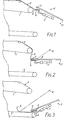
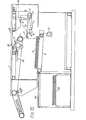
- the stacking machine is situated beyond a conveyor 1 which has a downwardly sloping rear portion 2.
- Articles are fed in the direction of the workflow on conveyor 1 and from portion 2 they are fed between a pair of open jaws 3, 4, the jaws being in a raised receiving position, as shown in Figure 1.
- the article is gripped by closing the jaws on the leading edge and the jaws are then swung down about a pivot P to a lower, release position so that the articles are placed on a stack on a discharge conveyor 5.
- This sequence is shown in Figures 2 and 3.
- the lower jaw 4 is pivoted at 6 and is closed by the application of air pressure to an air cylinder 7.
- Another air cylinder (not shown in Figures 1 to 6) which is arranged to move the mechanism is attached to the arm of the upper jaw 3.
- the lower j f w 4 is opened against the pneumatic pressure in cylinder 7 by the action of a mechanical linkage which co-operates with a fixed stop.
- the jaws are automatically opened when they reach the receiving position and similarly they close automatically to grip the article as the fixed stop is cleared when the jaws leave the receiving position.
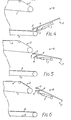
- the next operation is to release the hold which the jaws have of it and then reset the mechanism to receive the next one.
- Jaw release is effected by removing the air pressure from cylinder 7.
- the lower Jaw 4 drops to allow the article to be left on the stack and the mechanism to be returned to its receiving position.
- Figure 4 shows the lower jaw opened, Figure 5 shows the jaws being returned and Figure 6 shows the jaws open to accept the next article.
- the up and down movement and the lower jaw release movement are made by suitable air cylinders, valves and appropriate control systems.
- these operations can be made by other mechanical, hydraulic or electrical devices.
- This air flow stream can be made by a suitable air blower or a suction hood arranged over the stack deck, or by a nozzle and compressed air jet arrangement incorporated as part of the upper jaw plate design whereby the opening of an air valve will cause a stream of compressed air to be directed over the top of the gripped articles.
- the air stream arrangement shown in the drawings is preferred, however, and comprises a fixed air jet tube 8 having several jet holes and situated above the upper jaw 3 so as to direct air against a deflector plate mounted on the upper jaw at 9. Compressed air emitted from the jet holes entrains atmospheric air and by being first deflected by the deflector plate ( Figure 2) and then directed over the top of the stack ( Figure 3) ensures that the article is laid neatly on the stack.
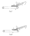
- Figure 7 shows detail of the mechanism whereby the lower jaw is withdrawn so that in being raised to the receiving position it does not lift and disturb the top article on the stack.
- Figure 8 shows an alternative form of lower jaw retraction method.
- the lower jaw 4 slides linearily and is actuated by an air cylinder 10 to be normally extended but to be withdrawn to the position in Figure 8 as the jaws are returned to the receiving position.
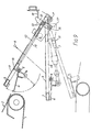
- FIG. 9 there is shown detail of the jaw pivot mechanism of tle Figure 7 arrangement.
- the lower jaw 4 is pivoted to the upper jaw 3 at 6 and is linked also to the piston of the air cylinder 7.
- the air cylinder is fixed at 11 and is effective to urge the jaws closed when pneumatic pressure is applied.
- a push-rod 12 is mounted to be slideable on the upper jaw arm and co-operates at one end and with a bracket 19 fixed to the lower jaw.
- the other end of the push-rod is pivotally coupled at 13 to a lever 15 pivoted at 16 to a plate 17 on the upper jaw arm.
- lever 15 makes contact with a fixed stop 18.
- Push-rod 12 is thus pushed forward along arm 14 as the mechanism is further raised, so urging the lower jaw open against the pressure in cylinder 7, which acts as an air spring.
- the jaws are thus opened automatically at the top of the stroke of the mechanism, and they close automatically under air pressure when the stop is cleared on the down stroke.
- a microswitch S2 is positioned to be operated by arm 14 at the top of the stroke.
- the stacking cycle is commenced when the edge of the article passes a sensing device (photocell or similar). As the jaw mechanism makes each cycle it will move to rest on top of the growing stack of articles. Therefore the stack deck does not need to be lowered as the stack grows in height.
- a sensing device photocell or similar.
- the deck can be a simple stop-start conveyor onto which the articles are stacked and when the bundle is complete, the conveyor is momentarily operated to discharge it from the system.
- the deck is a simple hinged platform which can be tilted to a steep angle from where the bundle will slide downward onto a discharge conveyor.
- FIG 10 there is shown the stacking mechanism with a discharge arrangement for discharging the stacks of articles beneath the machine in the opposite direction to the direction of. work flow on the conveyor 1.
- the direction of workflow is indicated by the arrow.
- the elements of the machine described with reference to Figures 1 to 7 are shown and in addition the air cylinder for moving the jaw mechanism is shown at 20.
- the discharge conveyor 5 on which the stack of articles is received is driven intermittently by a motor 21.
- motor 21 is energised and the stack is conveyed to a transfer deck 24. From there the articles are led away on a discharge conveyor 25.
- FIG 11 is a schematic end elevation of the discharge arrangement.
- a four-lane machine is shown, it being understood that there are four stacking mechanisms arranged side by side.
- the transfer decks for the four mechanisms are shown at 24a, 24b, 24c and 24d.
- Each is tilted when full by a mechanism (not shown) to allow the stack to slide on to the discharge conveyor 25. This conveys the stacks to a common collection point at 27.
- the tilting mechanisms are interlocked so that tilting is inhibited if another stack is passing beneath a transfer deck.
- Figure 12 shows an arrangement whereby the conveyor 5 is driven to discharge stacks to the rear of the machine. Discharge is to a simple table 31, since collection from here can be made manually. Alternatively, the table may be replaced by a conveyor.
- the system bypass mode arran taent will depend on:- (1) whether the system is to be i)corporated on the end of the process conveyor run or (2) inserted as part of the process conveyor run.
- the bypass operation is controlled by a series of guide fingers 28 ( Figure 10) which are movably mounted below the conveyor belts of the process conveyor 1 where they can be raised up and down in the gaps between these belts.
- a series of guide fingers 28 Figure 10
- the stacking machine When the stacking machine is located at the end of the process conveyor run it is fitted with a receiving table 29 onto which the bypassed work will be directed.
- the bypass guide fingers 28 When the bypass guide fingers 28 are raised by an air cylinder 30, the articles will be directed from the conveyor line onto the table 29. When the fingers are down the articles will pass under the table to the stacking system.
- the receiving table is replaced by a second conveyor.
- the bypass fingers are raised, the articles will be directed from the one conveyor onto the second and will continue through the process line. With the fingers down, the articles will pass under the second conveyor to the stacking system.
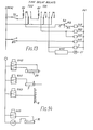
- a photocell switch S1 is positioned near the end of conveyor 1 to detect the presence of an article on the conveyor.
- the switch is normally on in the condition shown in Figure 13 and is switched off while a laundry article is present, obscuring the photocell.
- switch S1 is opened.
- Another time-delay relay TD1 is thereby energised.
- the time delays of relays TD1 and TD2 are such that the relays react immediately on being de-energised but react only after a predetermined time delay on being energised. Thus, after a predetermined delay sufficient to allow the leading edge of the article to reach the open jaws, relay TD1 reacts and contacts TD1/1 and TD1/2 are closed.
- Valve SV2 On closure of contacts TD1/1, solenoid valves SV2 and SV3 are energised. Valve SV2 is effective then to apply pressure to cylinder 20, which is two- way, in order to lower the jaw mechanism. The jaws then automatically close on the leading edge of the article, as has been described. Valve SV3 is effective to apply air to the air jet tube 8, so giving the stabilising stream of air over the article.
- Valve SV1 is effective to control air cylinder 7 which opens and closes the jaws.
- valve SV1 is controlled by contacts TD2/1 and the switch S2.
- switch S2 is a micro-switch situated at the top of the stroke of the jaw mechanism. When the jaws are in their uppermost position, switch S2 is open. Otherwise the switch is closed.
- De-energisation of SV1 allows air pressure to be applied to cylinder 7, thereby urging the jaws closed.
- Energisation of SV1 opens the jaws.
- the jaws are urged closed by operation of switch S2, but maintained open mechanically as described.
- On the downward stroke of the jaw mechanisation the jaws are maintained closed because contacts TD2/1 are open.
- the jaws are open.
- Contacts TD1/2 are effective to provide a pulse each time the relay is energised and thus each time an article is deposited on the stack.
- the pulses are used to count the articles in a totalizer piece counter C and in an electronic stack counter ESC.
- Counter C counts all the pieces until reset manually.
- Counter ESC on the other hand is set to a predetermined number of articles which will constitute a stack. When that number of articles has been achieved, the stack is complete and motor 21 is energised for a predetermined time to drive the stack from conveyor 5.
- Bypass is effected by operation of a manual switch BS which energises a solenoid valve SV5 effective to apply pressure to by-pass cylinder 30 which raises the by-pass fingers 28.
- Figure 14 is the pneumatic circuit diagram which shows the relationships described between the solenoid valves and their respective air cylinders and air jet tube.
- control system has been described in a mechanical/electrical form using relays, micro-switches and timers.
- the preferred control system will be fully electronic using a suitable programmed micro-processor system to perform all the necessary functions of counting, sequence, and stack discharge and inhibit operations for all lanes.
Landscapes
- Engineering & Computer Science (AREA)
- Mechanical Engineering (AREA)
- Branching, Merging, And Special Transfer Between Conveyors (AREA)
- Treatment Of Fiber Materials (AREA)
- Sheets, Magazines, And Separation Thereof (AREA)
- Specific Conveyance Elements (AREA)
Applications Claiming Priority (2)
| Application Number | Priority Date | Filing Date | Title |
|---|---|---|---|
| GB858507654A GB8507654D0 (en) | 1985-03-25 | 1985-03-25 | Stacking machine |
| GB8507654 | 1985-03-25 |
Publications (2)
| Publication Number | Publication Date |
|---|---|
| EP0202740A2 true EP0202740A2 (fr) | 1986-11-26 |
| EP0202740A3 EP0202740A3 (fr) | 1989-11-29 |
Family
ID=10576571
Family Applications (1)
| Application Number | Title | Priority Date | Filing Date |
|---|---|---|---|
| EP86302207A Withdrawn EP0202740A3 (fr) | 1985-03-25 | 1986-03-25 | Dispositif d'empilage d'articles en matière textile |
Country Status (5)
| Country | Link |
|---|---|
| US (1) | US4848763A (fr) |
| EP (1) | EP0202740A3 (fr) |
| AU (2) | AU5522586A (fr) |
| DK (1) | DK134486A (fr) |
| GB (1) | GB8507654D0 (fr) |
Cited By (2)
| Publication number | Priority date | Publication date | Assignee | Title |
|---|---|---|---|---|
| FR2620084A1 (fr) * | 1987-09-04 | 1989-03-10 | Polygraph Leipzig | Releveur a roues a aubes, pour la mise en rames de produits imprimes effectuee sans a-coup |
| EP0578551A1 (fr) * | 1992-07-07 | 1994-01-12 | SILIUM Société française à responsabilité limitée | Perfectionnements aux machines d'impression, notamment aux machines de sérigraphie |
Families Citing this family (3)
| Publication number | Priority date | Publication date | Assignee | Title |
|---|---|---|---|---|
| US5324017A (en) * | 1993-10-22 | 1994-06-28 | Lawson Screen Products, Inc. | Screen printing take-off device |
| US5758590A (en) * | 1996-02-22 | 1998-06-02 | Collier; Horace I. | Stacking device for sheet material |
| CN105480766A (zh) * | 2014-09-17 | 2016-04-13 | 柏创机械有限公司 | 软板料整平叠料机 |
Family Cites Families (8)
| Publication number | Priority date | Publication date | Assignee | Title |
|---|---|---|---|---|
| FR431799A (fr) * | 1911-06-30 | 1911-11-20 | Frederick William Vickery | Mécanisme pour transporter et mettre en piles les feuilles de papier |
| GB1169513A (en) * | 1966-01-31 | 1969-11-05 | Weir Henry J | Improvements in Laundry Feeding Machines. |
| GB1034815A (en) * | 1962-04-30 | 1966-07-06 | Kayser Bondor Ltd | An improved textile article stacker |
| FR1446477A (fr) * | 1965-06-11 | 1966-07-22 | Ramasseuse pour pièces de linge | |
| DE1269043B (de) * | 1965-09-10 | 1968-05-22 | American Safety Table Company | Vorrichtung zum Transport von flaechigen Teilen zwischen einer Abnahmestelle und einer Ablagestelle |
| US3704884A (en) * | 1970-03-05 | 1972-12-05 | Duerkoppwerke | Stacking device for flexible workpieces |
| US4512563A (en) * | 1982-10-26 | 1985-04-23 | American Screen Printing Equipment Company | Takeoff method and apparatus |
| US4511130A (en) * | 1983-07-28 | 1985-04-16 | Metromail Corporation | Phase controlled gripper operating system for collator |
-
1985
- 1985-03-25 GB GB858507654A patent/GB8507654D0/en active Pending
-
1986
- 1986-03-24 DK DK134486A patent/DK134486A/da not_active Application Discontinuation
- 1986-03-25 EP EP86302207A patent/EP0202740A3/fr not_active Withdrawn
- 1986-03-25 AU AU55225/86A patent/AU5522586A/en not_active Abandoned
- 1986-11-05 US US06/927,157 patent/US4848763A/en not_active Expired - Fee Related
-
1990
- 1990-01-29 AU AU48856/90A patent/AU4885690A/en not_active Abandoned
Cited By (3)
| Publication number | Priority date | Publication date | Assignee | Title |
|---|---|---|---|---|
| FR2620084A1 (fr) * | 1987-09-04 | 1989-03-10 | Polygraph Leipzig | Releveur a roues a aubes, pour la mise en rames de produits imprimes effectuee sans a-coup |
| EP0578551A1 (fr) * | 1992-07-07 | 1994-01-12 | SILIUM Société française à responsabilité limitée | Perfectionnements aux machines d'impression, notamment aux machines de sérigraphie |
| FR2693445A1 (fr) * | 1992-07-07 | 1994-01-14 | Silium | Perfectionnements aux machines d'impression notamment aux machines de sérigraphie. |
Also Published As
| Publication number | Publication date |
|---|---|
| US4848763A (en) | 1989-07-18 |
| AU5522586A (en) | 1986-10-02 |
| GB8507654D0 (en) | 1985-05-01 |
| DK134486A (da) | 1986-09-26 |
| AU4885690A (en) | 1990-05-24 |
| EP0202740A3 (fr) | 1989-11-29 |
| DK134486D0 (da) | 1986-03-24 |
Similar Documents
| Publication | Publication Date | Title |
|---|---|---|
| US5024042A (en) | Bag filling and closing apparatus | |
| AU2002358360B2 (en) | Pack opening apparatus and method | |
| US4921388A (en) | Envelope opener and load separator | |
| US3934388A (en) | Method and apparatus for handling bags | |
| US4445681A (en) | Apparatus for removing flexible flat products from a product stream | |
| US4701094A (en) | Separator for heterogenous flat objects | |
| DK167610B1 (da) | Apparat til at laegge flade genstande, isaer tryksager, oven paa hinanden | |
| US4537010A (en) | Palletizing system | |
| US4141392A (en) | Apparatus for automatic insertion of valved bags on bag-filling machines | |
| US4587792A (en) | Apparatus for opening box flaps on an article loading machine | |
| US5503388A (en) | Buffered stacker | |
| US3390875A (en) | Coupon feeder | |
| GB2377431A (en) | A device for lifting and separating sheets in a stack | |
| JPS58220040A (ja) | 薄片の堆積を搬出する方法および装置 | |
| US4666143A (en) | Apparatus for stacking flat products, especially printed products arriving in an imbricated stream | |
| EP0202740A2 (fr) | Dispositif d'empilage d'articles en matière textile | |
| US20230013252A1 (en) | Machine for automatically feeding flatwork articles | |
| US5096360A (en) | Envelope opener and load separator | |
| GB2087363A (en) | Individually transporting registered empty bags to an opening station | |
| US3583562A (en) | Methods of and apparatus for stacking veneer sheets | |
| US2792218A (en) | Mail handling equipment | |
| US4678173A (en) | Apparatus for automatically and continuously feeding and folding textile articles | |
| US4442874A (en) | Automatic valve bag placer | |
| US3405932A (en) | Apparatus for folding and stacking flexible material | |
| GB1309439A (en) | Apparatus for separating stacked flat articles and feeding them one at a time to a machine in which a subsequent operation can be performed on them |
Legal Events
| Date | Code | Title | Description |
|---|---|---|---|
| PUAI | Public reference made under article 153(3) epc to a published international application that has entered the european phase |
Free format text: ORIGINAL CODE: 0009012 |
|
| AK | Designated contracting states |
Kind code of ref document: A2 Designated state(s): BE CH DE FR GB IT LI NL |
|
| PUAL | Search report despatched |
Free format text: ORIGINAL CODE: 0009013 |
|
| AK | Designated contracting states |
Kind code of ref document: A3 Designated state(s): BE CH DE FR GB IT LI NL |
|
| 17P | Request for examination filed |
Effective date: 19900525 |
|
| 17Q | First examination report despatched |
Effective date: 19910502 |
|
| STAA | Information on the status of an ep patent application or granted ep patent |
Free format text: STATUS: THE APPLICATION IS DEEMED TO BE WITHDRAWN |
|
| 18D | Application deemed to be withdrawn |
Effective date: 19930319 |