EP0202738A1 - Cleaning appliance - Google Patents
Cleaning appliance Download PDFInfo
- Publication number
- EP0202738A1 EP0202738A1 EP86301953A EP86301953A EP0202738A1 EP 0202738 A1 EP0202738 A1 EP 0202738A1 EP 86301953 A EP86301953 A EP 86301953A EP 86301953 A EP86301953 A EP 86301953A EP 0202738 A1 EP0202738 A1 EP 0202738A1
- Authority
- EP
- European Patent Office
- Prior art keywords
- jaw
- appliance according
- blade
- jaws
- lever
- Prior art date
- Legal status (The legal status is an assumption and is not a legal conclusion. Google has not performed a legal analysis and makes no representation as to the accuracy of the status listed.)
- Granted
Links
Images


Classifications
-
- A—HUMAN NECESSITIES
- A47—FURNITURE; DOMESTIC ARTICLES OR APPLIANCES; COFFEE MILLS; SPICE MILLS; SUCTION CLEANERS IN GENERAL
- A47L—DOMESTIC WASHING OR CLEANING; SUCTION CLEANERS IN GENERAL
- A47L1/00—Cleaning windows
- A47L1/06—Hand implements
Definitions
- the invention relates to cleaning appliances such as squeegees or the like as commonly used for the cleaning of windows and/or floors, especially the former.
- appliances which comprise a head portion with a projecting handle section and on which a squeegee blade or the like is mountable, with the blade projecting laterally and releasably gripped between opposed jaws of the head portion.
- the object of the invention is to provide an appliance with a clamping arrangement which overcomes all, or at least some, of the disadvantages possessed by prior constructions.
- an appliance has a head portion with a rearwardly projecting handle section presenting at the front end opposed jaws between which a laterally projecting squeegee blade or the like can be releasably clamped, the clamping arrangement further comprising an operating member disposed at a front upper surface of the head and which is suitably positioned for single-handed operation by an operator using the thumb or forefinger of the hand in which the handle section is held.
- the operating member is pivotally or rotatably mounted on one of said jaws, for movement between an unclamping position (in which the blade is not gripped) and a clamping position in which it applies a jaw-closing force to the other of said jaws.
- the operating member may take the form of a lever, which is pivotable between said unclamping and clamping positions in the latter of which positions it engages said other jaw with a camming or eccentric action whereby to produce the jaw closing force to grip the blade.
- it may be the head of a clamping screw the screw-threaded stem of which engages a screw-threaded mounting on the upper jaw, which then provides said one jaw, with the end of the stem engaging the other lower jaw rearwardly of a connection between the jaws which allows the necessary relative angular movement thereof.
- the operating member may be a lever which pivots between the unclamping position and the clamping position on a pivot pin disposed laterally of the head and supported by a projection extending from said one jaw and passing through a clearance aperture in said other jaw, the latter being engaged by the lever with a camming action as the lever moves to the clamping position.
- an appliance has a head portion presenting at the front end opposed jaw members between which a laterally projecting squeegee blade or the like can be gripped, a clamp operating member in the form of a lever being mounted for pivotal movement between unclamping and clamping positions on a projection from one of the jaw members which projects through an aperture in the other jaw member for mounting of the lever which, as it moves to the clamping position, engages the other jaw member with a camming action to apply a closing force between the jaw members.
- the projection may be fixed to said one jaw member but in preferred constructions it is not so secured but comprises a stem which passes freely through an aperture in said one jaw member and presents a shoulder which engages the outer side of the latter.
- the shoulder may be provided by a self-locking nut screwed on to the stem.
- said other jaw member is the upper jaw member and is formed integrally with the handle section of the appliance, with said projecting stem securing the two jaw members together and the rear end of said one or lower jaw member engaging the upper jaw member to define a pivot axis for relative pivotal movement of the jaw members to the blade clamping position.
- Said camming action may be produced by an eccentric pivot boss of the lever which engages the outer surface of said other jaw member.
- the appliance may include a squeegee blade retained along its rear edge in a metal support channel positioned between the jaws, and both jaws may engage and grip this channel.
- the upper limb of the channel may be extended towards the front edge of the blade and inclined away from the latter forwardly of the upper jaw to provide a stop surface limiting flexing of the blade during use, and in this case the lower jaw of the appliance may be designed to clear the channel and engage the blade itself so that the latter is gripped between the upper channel limb and the lower jaw. This serves to retain and locate the blade in the support channel, so that retaining means such as end clips for axial retention of the blade in the channel are not required.
- the head of the appliance may be fitted with other devices similarly gripped between the jaws.
- the squeegee blade may be replaced by a scraper blade or a duster attachment, for example.
- the head may be adapted for the attachment of a washing device operative to supply water, or a cleaning solution, to the surface being cleaned during use of the appliance.
- the appliance which is illustrated therein comprises a head portion 1 presenting at the forward end upper and lower jaw members 2 and 3 between which a squeegee blade assembly 4 is removably gripped with a clamping action.
- the head portion 1 comprises a rearwardly projecting handle section 5, formed with the upper jaw member 2 as an integral sheet metal pressing with the handle section 5 rolled to provide a tapering tubular socket 5a allowing the head portion 1 to be mounted on an extension handle.
- a ribbed rubber sleeve 5b provides a handgrip when the section 5 is held in the hand of the user.
- the squeegee blade assembly 4 is of basically conventional construction with a metal support channel 6 in which the rubber squeegee blade proper is fitted.
- the channel 6 has a part-spherical bulbous base section 6a by which it is gripped between concave gripping sections 2a and 3a of the jaw members 2 and 3.
- the blade 7 has a complementary cross-section so that it is retained by the shape of the channel 6, and it is replaceably retained and located in the longitudinal axial direction within the channel by end clips 7a.
- Clamping means by which the jaw-closing force is applied between the jaw members 2 and 3 to grip the squeegee blade assembly 4 comprise an operating member in the form of a moulded plastics lever 8 disposed at the front upper surface la of the head portion 1 above the jaw member 2. It is mounted for pivotal movement, between unclamping and clamping positions (the latter of which is illustrated) on a laterally disposed pivot pin 9.
- the pin 9 is mounted in a cylindrical stem 10 which projects from the lower jaw member 3 through a clearance aperture in the upper jaw member 2.
- the lever 8 On each side of the stem 10 the lever 8 has a generally rectangular pivot boss 11 presenting an eccentric cam profile which engages the upper surface of the jaw member 2, within a laterally extending recessed portion 2b pressed therein, with a camming action to provide the jaw closing force in the position illustrated.
- the stem 10 passes through a clearance aperture in the lower jaw member 3, and at the lower end is threaded to receive a self-locking nut 12.
- This nut 12 provides an abutment which engages the lower jaw member 3 to apply the jaw closing force thereto.
- the stem and nut assembly 10,12 thus interconnects the jaw members 2 and 3 in a manner which allows self-aligning relative movement thereof, and at the rear the lower jaw member 3 has an upturned end section 3b which engages the upper jaw member 2 to provide a pivot abutment for relative pivotal movement of the jaw members 2 and 3.
- the nut 12 allows the effective length of the stem 10 to be adjusted, to provide the required blade gripping force in the clamping condition.
- the shape of the pivot bosses 11 and positioning of the pivot pin 9 is such that if the lever is flipped upwardly through 90° to the unclamping position, in which position it is self-retaining in a toggle-like manner, the jaw members 2 and 3 are free to open sufficiently to release the blade assembly 4.
- the upper limb 6b of the channel 6 is extended towards the front edge of the blade 7 and inclined away from the latter forwardly of the upper jaw member 2 to provide a stop which limits flexing of the blade 7 in use.
- both jaw members 2 and 3 directly engage and grip, respectively, the channel limbs 6b and 6c.
- the end clips 7a are required for axial retention of the squeegee blade 7 in the channel 6.
- the modification illustrated in Figs. 4 and 5 consists of a lower jaw member 30 which is a replacement for the jaw member 3 already described, all the other components of the appliance being unchanged.
- the jaw member 30 is identical with jaw member 3 except at its forwardly projecting end where the jaw pressing is extended by two spaced sections 31 which terminate in upwardly directed flanges 32.
- the lower jaw member 30 clears the lower limb 6c of the support channel 6 and the flanges 32 engage the squeegee blade 7.
- the blade 7 is directly clamped between the upper channel limb 6b and the flanges 32, so that clamping of the assembly 4 serves also to retain and locate the squeegee blade 4 in the axial direction within the channel 6.
- the end clips 7a shown in Figs. 1 and 2 can, if desired, be dispensed with when the jaw member 30 is used.
Landscapes
- Gripping Jigs, Holding Jigs, And Positioning Jigs (AREA)
- Electrical Discharge Machining, Electrochemical Machining, And Combined Machining (AREA)
- Manufacturing Of Electric Cables (AREA)
- Dry Shavers And Clippers (AREA)
- Filters For Electric Vacuum Cleaners (AREA)
- Cleaning Implements For Floors, Carpets, Furniture, Walls, And The Like (AREA)
Abstract
Description
- The invention relates to cleaning appliances such as squeegees or the like as commonly used for the cleaning of windows and/or floors, especially the former. In particular it relates to appliances which comprise a head portion with a projecting handle section and on which a squeegee blade or the like is mountable, with the blade projecting laterally and releasably gripped between opposed jaws of the head portion.
- Various releasable clamping arrangements have been proposed for such appliances but all of them suffer from disadvantages of complexity, cumbersomeness, lack of strength and/or the impossibility or difficulty of single-handed operation. The last of these disadvantages is of particular importance with a squeegee when used by a window cleaner who may wish to release and re-clamp the squeegee blade whilst working on a high ladder. In such situations it is highly desirable, on the grounds of safety, that the clamping means should be operable by the hand holding the appliance so that the other hand does not have to let go of the ladder.
- The object of the invention is to provide an appliance with a clamping arrangement which overcomes all, or at least some, of the disadvantages possessed by prior constructions.
- To this end an appliance, according to one aspect of the invention, has a head portion with a rearwardly projecting handle section presenting at the front end opposed jaws between which a laterally projecting squeegee blade or the like can be releasably clamped, the clamping arrangement further comprising an operating member disposed at a front upper surface of the head and which is suitably positioned for single-handed operation by an operator using the thumb or forefinger of the hand in which the handle section is held.
- Preferably the operating member is pivotally or rotatably mounted on one of said jaws, for movement between an unclamping position (in which the blade is not gripped) and a clamping position in which it applies a jaw-closing force to the other of said jaws. Thus it may take the form of a lever, which is pivotable between said unclamping and clamping positions in the latter of which positions it engages said other jaw with a camming or eccentric action whereby to produce the jaw closing force to grip the blade. Alternatively, it may be the head of a clamping screw the screw-threaded stem of which engages a screw-threaded mounting on the upper jaw, which then provides said one jaw, with the end of the stem engaging the other lower jaw rearwardly of a connection between the jaws which allows the necessary relative angular movement thereof.
- The operating member may be a lever which pivots between the unclamping position and the clamping position on a pivot pin disposed laterally of the head and supported by a projection extending from said one jaw and passing through a clearance aperture in said other jaw, the latter being engaged by the lever with a camming action as the lever moves to the clamping position.
- Hence, according to another aspect of the invention, an appliance has a head portion presenting at the front end opposed jaw members between which a laterally projecting squeegee blade or the like can be gripped, a clamp operating member in the form of a lever being mounted for pivotal movement between unclamping and clamping positions on a projection from one of the jaw members which projects through an aperture in the other jaw member for mounting of the lever which, as it moves to the clamping position, engages the other jaw member with a camming action to apply a closing force between the jaw members.
- The projection may be fixed to said one jaw member but in preferred constructions it is not so secured but comprises a stem which passes freely through an aperture in said one jaw member and presents a shoulder which engages the outer side of the latter. The shoulder may be provided by a self-locking nut screwed on to the stem. Preferably said other jaw member is the upper jaw member and is formed integrally with the handle section of the appliance, with said projecting stem securing the two jaw members together and the rear end of said one or lower jaw member engaging the upper jaw member to define a pivot axis for relative pivotal movement of the jaw members to the blade clamping position. Said camming action may be produced by an eccentric pivot boss of the lever which engages the outer surface of said other jaw member.
- The appliance may include a squeegee blade retained along its rear edge in a metal support channel positioned between the jaws, and both jaws may engage and grip this channel. The upper limb of the channel may be extended towards the front edge of the blade and inclined away from the latter forwardly of the upper jaw to provide a stop surface limiting flexing of the blade during use, and in this case the lower jaw of the appliance may be designed to clear the channel and engage the blade itself so that the latter is gripped between the upper channel limb and the lower jaw. This serves to retain and locate the blade in the support channel, so that retaining means such as end clips for axial retention of the blade in the channel are not required.
- It will be appreciated that as an alternative to a squeegee blade, in connection with which the invention is more particularly described herein, the head of the appliance may be fitted with other devices similarly gripped between the jaws. Thus the squeegee blade may be replaced by a scraper blade or a duster attachment, for example. The head may be adapted for the attachment of a washing device operative to supply water, or a cleaning solution, to the surface being cleaned during use of the appliance.
- The invention will now be further described with reference to the accompanying drawings which illustrate, by way of example, a squeegee construction representing a preferred embodiment of the invention. In the drawings:
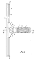
- Fig. 1 is an upper face view of one embodiment;
- Fig. 2 is a corresponding lower face view;
- Fig. 3 is a cross-sectional view on the line III-III in Fig. 1;
- Fig. 4 is a side view showing a modification; and
- Fig. 5 is a detail view of the modification, from below.
- Referring to Figs. 1 to 3, the appliance which is illustrated therein comprises a
head portion 1 presenting at the forward end upper andlower jaw members 2 and 3 between which asqueegee blade assembly 4 is removably gripped with a clamping action. When thejaw members 2 and 3 are in a relative unclamping position the laterally projectingsqueegee blade assembly 4 is freely slidable between them, for lateral adjustment or for removal and replacement. Thehead portion 1 comprises a rearwardly projectinghandle section 5, formed with theupper jaw member 2 as an integral sheet metal pressing with thehandle section 5 rolled to provide a tapering tubular socket 5a allowing thehead portion 1 to be mounted on an extension handle. A ribbedrubber sleeve 5b provides a handgrip when thesection 5 is held in the hand of the user. - The
squeegee blade assembly 4 is of basically conventional construction with ametal support channel 6 in which the rubber squeegee blade proper is fitted. Thechannel 6 has a part-spherical bulbous base section 6a by which it is gripped betweenconcave gripping sections 2a and 3a of thejaw members 2 and 3. Theblade 7 has a complementary cross-section so that it is retained by the shape of thechannel 6, and it is replaceably retained and located in the longitudinal axial direction within the channel byend clips 7a. - Clamping means by which the jaw-closing force is applied between the
jaw members 2 and 3 to grip thesqueegee blade assembly 4 comprise an operating member in the form of a mouldedplastics lever 8 disposed at the front upper surface la of thehead portion 1 above thejaw member 2. It is mounted for pivotal movement, between unclamping and clamping positions (the latter of which is illustrated) on a laterally disposedpivot pin 9. Thepin 9 is mounted in acylindrical stem 10 which projects from the lower jaw member 3 through a clearance aperture in theupper jaw member 2. On each side of thestem 10 thelever 8 has a generallyrectangular pivot boss 11 presenting an eccentric cam profile which engages the upper surface of thejaw member 2, within a laterally extendingrecessed portion 2b pressed therein, with a camming action to provide the jaw closing force in the position illustrated. - The
stem 10 passes through a clearance aperture in the lower jaw member 3, and at the lower end is threaded to receive a self-locking nut 12. Thisnut 12 provides an abutment which engages the lower jaw member 3 to apply the jaw closing force thereto. The stem andnut assembly jaw members 2 and 3 in a manner which allows self-aligning relative movement thereof, and at the rear the lower jaw member 3 has anupturned end section 3b which engages theupper jaw member 2 to provide a pivot abutment for relative pivotal movement of thejaw members 2 and 3. Thenut 12 allows the effective length of thestem 10 to be adjusted, to provide the required blade gripping force in the clamping condition. The shape of thepivot bosses 11 and positioning of thepivot pin 9 is such that if the lever is flipped upwardly through 90° to the unclamping position, in which position it is self-retaining in a toggle-like manner, thejaw members 2 and 3 are free to open sufficiently to release theblade assembly 4. - As shown in Fig. 3 the
upper limb 6b of thechannel 6 is extended towards the front edge of theblade 7 and inclined away from the latter forwardly of theupper jaw member 2 to provide a stop which limits flexing of theblade 7 in use. As can also be seen from that figure bothjaw members 2 and 3 directly engage and grip, respectively, thechannel limbs end clips 7a are required for axial retention of thesqueegee blade 7 in thechannel 6. - The modification illustrated in Figs. 4 and 5 consists of a
lower jaw member 30 which is a replacement for the jaw member 3 already described, all the other components of the appliance being unchanged. Thejaw member 30 is identical with jaw member 3 except at its forwardly projecting end where the jaw pressing is extended by two spacedsections 31 which terminate in upwardly directedflanges 32. As shown in Fig. 4, in the clamping position thelower jaw member 30 clears thelower limb 6c of thesupport channel 6 and theflanges 32 engage thesqueegee blade 7. Thus theblade 7 is directly clamped between theupper channel limb 6b and theflanges 32, so that clamping of theassembly 4 serves also to retain and locate thesqueegee blade 4 in the axial direction within thechannel 6. In view of this theend clips 7a shown in Figs. 1 and 2 can, if desired, be dispensed with when thejaw member 30 is used.
Claims (13)
Priority Applications (1)
| Application Number | Priority Date | Filing Date | Title |
|---|---|---|---|
| AT86301953T ATE54046T1 (en) | 1985-03-19 | 1986-03-18 | CLEANING DEVICE. |
Applications Claiming Priority (2)
| Application Number | Priority Date | Filing Date | Title |
|---|---|---|---|
| GB858507084A GB8507084D0 (en) | 1985-03-19 | 1985-03-19 | Cleaning appliance |
| GB8507084 | 1985-03-19 |
Publications (2)
| Publication Number | Publication Date |
|---|---|
| EP0202738A1 true EP0202738A1 (en) | 1986-11-26 |
| EP0202738B1 EP0202738B1 (en) | 1990-06-27 |
Family
ID=10576240
Family Applications (1)
| Application Number | Title | Priority Date | Filing Date |
|---|---|---|---|
| EP86301953A Expired - Lifetime EP0202738B1 (en) | 1985-03-19 | 1986-03-18 | Cleaning appliance |
Country Status (5)
| Country | Link |
|---|---|
| US (1) | US4777694A (en) |
| EP (1) | EP0202738B1 (en) |
| AT (1) | ATE54046T1 (en) |
| DE (1) | DE3672191D1 (en) |
| GB (2) | GB8507084D0 (en) |
Cited By (2)
| Publication number | Priority date | Publication date | Assignee | Title |
|---|---|---|---|---|
| EP0215564B1 (en) * | 1985-08-19 | 1990-05-02 | Steccone Products Co. | Improved squeegee |
| FR2659042A1 (en) * | 1990-03-02 | 1991-09-06 | Astel Sarl | Device for dismantleably joining a handle to a tool, and more particularly, but not exclusively, a device for dismantleably joining a handle to a file for surgical use and handle and tools designed to be joined in this way |
Families Citing this family (24)
| Publication number | Priority date | Publication date | Assignee | Title |
|---|---|---|---|---|
| US4941228A (en) * | 1988-12-09 | 1990-07-17 | Belanger Daniel J | Fastening mechanism for squeegee holder |
| US4993101A (en) * | 1989-10-12 | 1991-02-19 | Mr. Longarm, Inc. | Tool system with rotatable tool |
| US5293662A (en) * | 1991-09-18 | 1994-03-15 | Mr. Longarm, Inc. | Corner paint pad assembly |
| CA2138144A1 (en) * | 1992-06-16 | 1993-12-23 | Jacob Wilhelmus Erken | Improvements in wiping devices |
| AU668185B2 (en) * | 1992-06-16 | 1996-04-26 | Jacob Wilhelmus Erken | Improvements in wiping devices |
| US5930863A (en) * | 1997-09-05 | 1999-08-03 | Samuelsson; Soren | Quick release squeegee |
| WO2001058332A1 (en) * | 2000-02-09 | 2001-08-16 | Goldtime Products, Llc | A universal clip-on handle for a water wiper blade |
| US6499175B1 (en) | 2000-09-18 | 2002-12-31 | Scott Osiecki | Combination scrub brush |
| US6931690B2 (en) * | 2003-05-15 | 2005-08-23 | Grant Cox | Spring-biased pivoting squeegee |
| EP1662958B1 (en) * | 2003-09-09 | 2013-04-24 | Pulex S.R.L. | Squeegee for surface cleaning |
| AU2004222856B2 (en) * | 2003-11-03 | 2010-07-29 | Raven Products Pty Ltd | Squeegee holder |
| US8726451B2 (en) | 2011-01-07 | 2014-05-20 | Unger Marketing International, Llc | Surface cleaning tools having end caps |
| USD649314S1 (en) * | 2011-01-07 | 2011-11-22 | Unger Marketing International, Llc | Window cleaning tool |
| US20150052700A1 (en) * | 2013-08-21 | 2015-02-26 | Keith Dvorchak | Floor Check |
| USD773766S1 (en) * | 2014-10-07 | 2016-12-06 | Unger Marketing International, Llc | Floor squeegee device |
| US9913565B2 (en) | 2014-10-07 | 2018-03-13 | Unger Marketing International, Llc | Squeegee devices with one or more collection features |
| USD919321S1 (en) * | 2014-11-19 | 2021-05-18 | Interdesign, Inc. | Dispenser |
| USD775909S1 (en) | 2015-04-29 | 2017-01-10 | Unger Marketing International, Llc | Tool handle |
| USD787142S1 (en) | 2015-11-17 | 2017-05-16 | Unger Marketing International, Llc | Window cleaning device |
| USD792043S1 (en) | 2015-12-31 | 2017-07-11 | Unger Marketing International, Llc | Cleaning tool |
| USD936317S1 (en) | 2018-08-30 | 2021-11-16 | The Libman Company | Cleaning tool |
| USD1072405S1 (en) * | 2023-01-30 | 2025-04-22 | Unger Marketing International, Llc | Squeegee tool having a fixed blade |
| USD1038562S1 (en) * | 2023-02-28 | 2024-08-06 | William Eldridge | Scraper |
| EP4640126A1 (en) * | 2024-04-24 | 2025-10-29 | Filmop International s.r.l. | Squeegee with an easy-to-change cleaning blade |
Citations (4)
| Publication number | Priority date | Publication date | Assignee | Title |
|---|---|---|---|---|
| FR2205300A1 (en) * | 1972-11-06 | 1974-05-31 | Unger Henry | |
| DE7536307U (en) * | 1975-11-15 | 1976-03-18 | Coronet - Werke Heinrich Schlerf Gmbh, 6948 Wald-Michelbach | WINDOW WIPER |
| US4336624A (en) * | 1979-12-03 | 1982-06-29 | Flo-Pac Corporation | Squeegee assembly |
| DE3301775A1 (en) * | 1982-01-29 | 1983-09-22 | Henri 67300 Schiltigheim Balzer | Cleaning device |
Family Cites Families (23)
| Publication number | Priority date | Publication date | Assignee | Title |
|---|---|---|---|---|
| DE501604C (en) * | 1930-07-03 | Karl Doerfer | Two-part handle sleeve encompassing the brushwood | |
| DE97019C (en) * | ||||
| AT86603B (en) * | 1918-05-18 | 1921-12-10 | Elisabeth Johnsen | Holder for cleaning, abrasive cloths, etc. like |
| US1478339A (en) * | 1922-10-16 | 1923-12-18 | Wade H Jayne | Mop head |
| GB215124A (en) * | 1923-02-13 | 1924-05-08 | George Pine | An adjustable holder for a household cleaning cloth |
| FR572388A (en) * | 1923-10-26 | 1924-06-04 | Squeegee | |
| GB372558A (en) * | 1931-05-09 | 1932-05-12 | Robert Bayley Sidebottom | Improvements in devices for holding cleaning or similar material |
| US2123638A (en) * | 1936-10-24 | 1938-07-12 | Steccone Ettore | Squeegee |
| US2261475A (en) * | 1939-08-26 | 1941-11-04 | William E Kautenberg | Squeegee |
| US2440099A (en) * | 1944-09-23 | 1948-04-20 | Kind Jacob | Squeegee with blade-holding grip responsive to handle setting |
| GB658331A (en) * | 1949-07-12 | 1951-10-10 | Kleen E Ze Brush Company Ltd | Improvements in or relating to brush, mop and the like holders |
| GB758185A (en) * | 1952-07-22 | 1956-10-03 | Lewis Motley | Improvements in and relating to fastening devices |
| US2771626A (en) * | 1953-09-09 | 1956-11-27 | Morse Starrett Products Compan | Spring actuated squeegee holding clamp |
| US2905960A (en) * | 1953-10-12 | 1959-09-29 | Morse Starrett Products Co | Squeegee |
| US2864110A (en) * | 1954-05-28 | 1958-12-16 | Louise Taffe | Shaft and holder for cleaning implements |
| US2814822A (en) * | 1956-05-24 | 1957-12-03 | Roy W Page | Adjustable window wiping squeegee |
| US3110052A (en) * | 1961-05-08 | 1963-11-12 | Fuller Brush Co | Squeegee having a handle particularly adapted for detachable connection to a brush |
| GB1222538A (en) * | 1968-06-14 | 1971-02-17 | Geerpres Europ Ltd | Improvements in or relating to surface treatment devices |
| US3496616A (en) * | 1968-08-15 | 1970-02-24 | Frank B Vazquez | Gripping and locking device |
| US3813724A (en) * | 1971-10-25 | 1974-06-04 | H Unger | Holder for replaceable cleaning element |
| FR2352193A1 (en) * | 1976-05-18 | 1977-12-16 | Meys Willy | DEVICE ALLOWING THE ADJUSTABLE BLOCKING OF A MOBILE PART FROM A FIXED FRAME |
| DE3138445A1 (en) * | 1981-09-24 | 1983-03-31 | Arenhold, Knut, 2000 Hamburg | SPRING CLAMP, ESPECIALLY FOR FASTENING DIRT SCREWERS ON MOTOR VEHICLES |
| US4697296A (en) * | 1985-08-19 | 1987-10-06 | Steccone Products Company, Inc. | Squeegee |
-
1985
- 1985-03-19 GB GB858507084A patent/GB8507084D0/en active Pending
-
1986
- 1986-03-17 GB GB8606535A patent/GB2172836B/en not_active Expired
- 1986-03-18 US US06/841,106 patent/US4777694A/en not_active Expired - Lifetime
- 1986-03-18 AT AT86301953T patent/ATE54046T1/en not_active IP Right Cessation
- 1986-03-18 EP EP86301953A patent/EP0202738B1/en not_active Expired - Lifetime
- 1986-03-18 DE DE8686301953T patent/DE3672191D1/en not_active Expired - Lifetime
Patent Citations (4)
| Publication number | Priority date | Publication date | Assignee | Title |
|---|---|---|---|---|
| FR2205300A1 (en) * | 1972-11-06 | 1974-05-31 | Unger Henry | |
| DE7536307U (en) * | 1975-11-15 | 1976-03-18 | Coronet - Werke Heinrich Schlerf Gmbh, 6948 Wald-Michelbach | WINDOW WIPER |
| US4336624A (en) * | 1979-12-03 | 1982-06-29 | Flo-Pac Corporation | Squeegee assembly |
| DE3301775A1 (en) * | 1982-01-29 | 1983-09-22 | Henri 67300 Schiltigheim Balzer | Cleaning device |
Cited By (2)
| Publication number | Priority date | Publication date | Assignee | Title |
|---|---|---|---|---|
| EP0215564B1 (en) * | 1985-08-19 | 1990-05-02 | Steccone Products Co. | Improved squeegee |
| FR2659042A1 (en) * | 1990-03-02 | 1991-09-06 | Astel Sarl | Device for dismantleably joining a handle to a tool, and more particularly, but not exclusively, a device for dismantleably joining a handle to a file for surgical use and handle and tools designed to be joined in this way |
Also Published As
| Publication number | Publication date |
|---|---|
| GB2172836B (en) | 1989-04-19 |
| EP0202738B1 (en) | 1990-06-27 |
| DE3672191D1 (en) | 1990-08-02 |
| GB8606535D0 (en) | 1986-04-23 |
| GB8507084D0 (en) | 1985-04-24 |
| US4777694A (en) | 1988-10-18 |
| GB2172836A (en) | 1986-10-01 |
| ATE54046T1 (en) | 1990-07-15 |
Similar Documents
| Publication | Publication Date | Title |
|---|---|---|
| EP0202738A1 (en) | Cleaning appliance | |
| US6795999B1 (en) | Cleaning apparatus and system | |
| US6671930B2 (en) | Adjustable tool mount apparatus and specialized tool handle thereof | |
| US5455981A (en) | Paint scraper | |
| US8516925B2 (en) | Extendable multi-tool including interchangable light bulb changer and accessories | |
| US6742222B2 (en) | Dual handle attachment for an appliance | |
| US3455638A (en) | Device for cleaning window surfaces | |
| US6113085A (en) | Clamping device | |
| US11772256B2 (en) | Dual ended handle for an implement | |
| JPS5838196B2 (en) | razor handle | |
| EP0215564B1 (en) | Improved squeegee | |
| US5832563A (en) | Forearm assistant device | |
| US5930863A (en) | Quick release squeegee | |
| US2741788A (en) | Wiper cleaner attachment | |
| PT719107E (en) | MANUAL APPARATUS FOR CLEANING SMOOTH SURFACES | |
| US20120012677A1 (en) | Spray gun handle support and quick release trigger assembly | |
| JP2003503132A (en) | Cleaning tools for smooth surfaces, especially for window cleaning | |
| US2655413A (en) | Adjustable connector device for mop or broom handles | |
| JPS63290537A (en) | Cleaning apparatus for polishing especially window glass | |
| US6625840B1 (en) | Squeegee apparatus having easily replaceable blade member | |
| CN113853278B (en) | Side handle for hand-held electric power tool | |
| US2225432A (en) | Squeegee | |
| US4376456A (en) | Hack saw frame | |
| CN220124171U (en) | Rotatable adjustment cleaner | |
| US3115657A (en) | Adjustable mop head |
Legal Events
| Date | Code | Title | Description |
|---|---|---|---|
| PUAI | Public reference made under article 153(3) epc to a published international application that has entered the european phase |
Free format text: ORIGINAL CODE: 0009012 |
|
| AK | Designated contracting states |
Kind code of ref document: A1 Designated state(s): AT BE CH DE FR IT LI LU NL SE |
|
| 17P | Request for examination filed |
Effective date: 19861231 |
|
| 17Q | First examination report despatched |
Effective date: 19880822 |
|
| ITF | It: translation for a ep patent filed | ||
| RAP1 | Party data changed (applicant data changed or rights of an application transferred) |
Owner name: BRUTE LIMITED |
|
| GRAA | (expected) grant |
Free format text: ORIGINAL CODE: 0009210 |
|
| AK | Designated contracting states |
Kind code of ref document: B1 Designated state(s): AT BE CH DE FR IT LI LU NL SE |
|
| REF | Corresponds to: |
Ref document number: 54046 Country of ref document: AT Date of ref document: 19900715 Kind code of ref document: T |
|
| REF | Corresponds to: |
Ref document number: 3672191 Country of ref document: DE Date of ref document: 19900802 |
|
| ET | Fr: translation filed | ||
| RAP2 | Party data changed (patent owner data changed or rights of a patent transferred) |
Owner name: SCOT YOUNG RESEARCH LIMITED |
|
| REG | Reference to a national code |
Ref country code: CH Ref legal event code: PFA Free format text: SCOT YOUNG RESEARCH LIMITED |
|
| NLT2 | Nl: modifications (of names), taken from the european patent patent bulletin |
Owner name: SCOT YOUNG RESEARCH LIMITED TE LYE, GROOT-BRITTANN |
|
| PG25 | Lapsed in a contracting state [announced via postgrant information from national office to epo] |
Ref country code: AT Effective date: 19910318 |
|
| PG25 | Lapsed in a contracting state [announced via postgrant information from national office to epo] |
Ref country code: LU Free format text: LAPSE BECAUSE OF NON-PAYMENT OF DUE FEES Effective date: 19910331 Ref country code: LI Effective date: 19910331 Ref country code: CH Effective date: 19910331 Ref country code: BE Effective date: 19910331 |
|
| ITPR | It: changes in ownership of a european patent |
Owner name: CAMBIO RAGIONE SOCIALE;SCOT YOUNG RESEARCH LIMITED |
|
| PLBE | No opposition filed within time limit |
Free format text: ORIGINAL CODE: 0009261 |
|
| STAA | Information on the status of an ep patent application or granted ep patent |
Free format text: STATUS: NO OPPOSITION FILED WITHIN TIME LIMIT |
|
| 26N | No opposition filed | ||
| BERE | Be: lapsed |
Owner name: SCOT YOUNG RESEARCH LTD Effective date: 19910331 |
|
| PG25 | Lapsed in a contracting state [announced via postgrant information from national office to epo] |
Ref country code: FR Effective date: 19911129 |
|
| REG | Reference to a national code |
Ref country code: CH Ref legal event code: PL |
|
| REG | Reference to a national code |
Ref country code: FR Ref legal event code: ST |
|
| ITTA | It: last paid annual fee | ||
| EAL | Se: european patent in force in sweden |
Ref document number: 86301953.5 |
|
| PGFP | Annual fee paid to national office [announced via postgrant information from national office to epo] |
Ref country code: SE Payment date: 19980317 Year of fee payment: 13 |
|
| PGFP | Annual fee paid to national office [announced via postgrant information from national office to epo] |
Ref country code: NL Payment date: 19980326 Year of fee payment: 13 |
|
| PG25 | Lapsed in a contracting state [announced via postgrant information from national office to epo] |
Ref country code: SE Free format text: LAPSE BECAUSE OF NON-PAYMENT OF DUE FEES Effective date: 19990319 |
|
| PG25 | Lapsed in a contracting state [announced via postgrant information from national office to epo] |
Ref country code: NL Free format text: LAPSE BECAUSE OF NON-PAYMENT OF DUE FEES Effective date: 19991001 |
|
| EUG | Se: european patent has lapsed |
Ref document number: 86301953.5 |
|
| NLV4 | Nl: lapsed or anulled due to non-payment of the annual fee |
Effective date: 19991001 |
|
| EUG | Se: european patent has lapsed |
Ref document number: 86301953.5 |
|
| PGFP | Annual fee paid to national office [announced via postgrant information from national office to epo] |
Ref country code: DE Payment date: 20010312 Year of fee payment: 16 |
|
| PG25 | Lapsed in a contracting state [announced via postgrant information from national office to epo] |
Ref country code: DE Free format text: LAPSE BECAUSE OF NON-PAYMENT OF DUE FEES Effective date: 20021001 |
|
| PG25 | Lapsed in a contracting state [announced via postgrant information from national office to epo] |
Ref country code: IT Free format text: LAPSE BECAUSE OF NON-PAYMENT OF DUE FEES;WARNING: LAPSES OF ITALIAN PATENTS WITH EFFECTIVE DATE BEFORE 2007 MAY HAVE OCCURRED AT ANY TIME BEFORE 2007. THE CORRECT EFFECTIVE DATE MAY BE DIFFERENT FROM THE ONE RECORDED. Effective date: 20050318 |