EP0202734B1 - Dispositif pour le déploiement des ailettes - Google Patents
Dispositif pour le déploiement des ailettes Download PDFInfo
- Publication number
- EP0202734B1 EP0202734B1 EP86301702A EP86301702A EP0202734B1 EP 0202734 B1 EP0202734 B1 EP 0202734B1 EP 86301702 A EP86301702 A EP 86301702A EP 86301702 A EP86301702 A EP 86301702A EP 0202734 B1 EP0202734 B1 EP 0202734B1
- Authority
- EP
- European Patent Office
- Prior art keywords
- fin member
- fin
- spring means
- spring
- profiled surface
- Prior art date
- Legal status (The legal status is an assumption and is not a legal conclusion. Google has not performed a legal analysis and makes no representation as to the accuracy of the status listed.)
- Expired
Links
- 230000007246 mechanism Effects 0.000 title claims description 12
- 210000003127 knee Anatomy 0.000 claims description 6
- 230000006837 decompression Effects 0.000 claims description 4
- 238000004519 manufacturing process Methods 0.000 description 2
- 230000013011 mating Effects 0.000 description 2
- 230000000717 retained effect Effects 0.000 description 1
- 230000003019 stabilising effect Effects 0.000 description 1
Images
Classifications
-
- F—MECHANICAL ENGINEERING; LIGHTING; HEATING; WEAPONS; BLASTING
- F42—AMMUNITION; BLASTING
- F42B—EXPLOSIVE CHARGES, e.g. FOR BLASTING, FIREWORKS, AMMUNITION
- F42B10/00—Means for influencing, e.g. improving, the aerodynamic properties of projectiles or missiles; Arrangements on projectiles or missiles for stabilising, steering, range-reducing, range-increasing or fall-retarding
- F42B10/02—Stabilising arrangements
- F42B10/14—Stabilising arrangements using fins spread or deployed after launch, e.g. after leaving the barrel
Definitions
- This invention relates to fin erecting mechanisms and is more particularly concerned with spring actuators for deploying stabilising fins on board a projectile such as a guided weapon.
- a fin erecting mechanism according to the preamble of claim 1 and comprising a fin member and means for pivotably attaching the fin member to support means so that the fin member is movable from a stowed position to a deployed position, and further comprising spring means operable to deploy the fin member.
- GB Patent No. 1431619 discloses a fin erecting mechanism of this known type.
- GB 1431619 discloses missile tail fins which are urged into a radially extending deployed position by a double- armed torsion spring terminating in a cross-bar which locks in a slot to lock the pin in the deployed position.
- the spring is mounted on an axle extending through a cross piece on which the fin is mounted.
- a fin errecting mechanism is- characterised in that the spring means comprises a cantilever which is attached to the fin member at a point remote from said pivotably attaching means and which extends towards said attaching means and which has a free end for abutting the support means.
- the free end of the cantilever- type spring means is close to the pivot point of the fin member which gives good advantage in terms of the force/deflection characteristics of the spring means.
- the spring means is further operable to retain the fin member in its deployed position.
- a fin erecting mechanism according to the present invention enables the use of a cam-type locking arrangement which is tolerant of manufacturing errors.
- the spring means forms an integral part of the fin member, advantageously reducing the number of parts required.
- the invention further provides a projectile comprising a fin erecting mechanism as defined above wherein the projectile is characterised by a surface against which the free end of the spring means (4) abuts and which is profiled for compressing the spring means (4) when the fin member is stowed.
- the profiled surface comprises a first portion in contact with the spring means when the fin member is stowed, the first portion being configured for permitting relatively little decompression of the spring means for a given pivotal movement of the fin member, and the profiled surface further comprises a second portion in contact with the spring means when the fin member is deployed, the second portion being configured for permitting relatively large decompression of the spring means for a given pivotal movement of the fin member.
- the first and second portions of the profiled surface may be joined at a knee or they may be joined by a curved surface.
- the free end of the spring means may cooperate with a portion of the profiled surface to maintain deployment of the fin member and, in the embodiment to be described, the free end of the spring means extends generally perpendicularly to the profiled surface when the fin member is deployed.
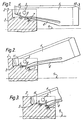
- the fin 1 shown in the Figures 1 and 2 is mounted on a support structure 2 which forms part of the missile body (not shown), via a pivot 3 which allows rotational movement of the fin 1 with respect to the support 2.
- the fin 1 has an integral spring member 4 in the form of:a cantilever.
- the spring 4 is tapered so that the greatest force is obtained for a given deflection for a near constant stress level within the elastic limits of the material.
- the support 2 comprises an abutment portion 5, and two sloping mating surfaces 6 and 7 which are connected together by means of a 'knee' portion 8.
- the fin 1 In the stowed position i.e. with the fin in towards the missile axis, the fin 1 lies parallel to the axis 9 and is retained in position with one end of the spring 4 lying in contact with the mating surface 6, by retaining means (not shown), against the action of the spring member.
- the fin When the fin is deployed i.e. the retaining means released, the fin 1 is pushed upwards in the direction of the arrow 10 in Figure 1 by the action of the spring 4, until an angled portion 11 of the fin engages with the abutment 5 as in Figure 2.
- the spring 4 In this position, the spring 4 is no longer in contact with the surface 6 but has passed over the 'knee' 8 and is in contact with the other surface 7.
- the fin 1 tends to be maintained in this position as a relatively large force is required to return the spring 4 up the surface 7 and back over the 'knee' 8.
- the surfaces 6 and 7 and the 'knee' 8 may be replaced by a curved surface.
- the deployment of the fin 1 may be tested and the fin 1 can then be restored to its stowed position by applying a great enough force.
- the fin 1 is locked in its deployed position. This is shown in Figure 3. Locking of the fin 1 in its deployed position is achieved if the free end of the spring 4 is normal to the surface 7. Once locked, the fin 1 can only be restowed by physically deflecting the end of the spring 4 and not by applying a force directly on to the fin itself.
- a plurality of such fins may be mounted on board a missile and may be used to stabilise the flight of the missile by controlling the spin rate. These fins may be mounted at the back of the missile and/or may be fully stowed inside the missile body before deployment.
Landscapes
- Physics & Mathematics (AREA)
- Fluid Mechanics (AREA)
- Engineering & Computer Science (AREA)
- General Engineering & Computer Science (AREA)
- Toys (AREA)
Claims (9)
Applications Claiming Priority (2)
| Application Number | Priority Date | Filing Date | Title |
|---|---|---|---|
| GB8507614 | 1985-03-23 | ||
| GB8507614 | 1985-03-23 |
Publications (2)
| Publication Number | Publication Date |
|---|---|
| EP0202734A1 EP0202734A1 (fr) | 1986-11-26 |
| EP0202734B1 true EP0202734B1 (fr) | 1989-06-28 |
Family
ID=10576535
Family Applications (1)
| Application Number | Title | Priority Date | Filing Date |
|---|---|---|---|
| EP86301702A Expired EP0202734B1 (fr) | 1985-03-23 | 1986-03-10 | Dispositif pour le déploiement des ailettes |
Country Status (3)
| Country | Link |
|---|---|
| US (1) | US4714216A (fr) |
| EP (1) | EP0202734B1 (fr) |
| DE (1) | DE3664164D1 (fr) |
Families Citing this family (6)
| Publication number | Priority date | Publication date | Assignee | Title |
|---|---|---|---|---|
| DE4119613C2 (de) * | 1991-06-14 | 1997-03-27 | Diehl Gmbh & Co | Flugkörper mit ausklappbaren Leiteinrichtungen |
| US5582364A (en) * | 1991-11-07 | 1996-12-10 | Hughes Missile Systems Company | Flyable folding fin |
| FR2712679B1 (fr) * | 1993-11-16 | 1996-02-09 | Luchaire Defense Sa | Dispositif de déploiement pour une ailette de stabilisation de projectile de type roquette. |
| US7566028B2 (en) * | 2006-10-26 | 2009-07-28 | Raytheon Company | Integral locking mechanism for deployable device |
| US7902489B2 (en) * | 2007-12-17 | 2011-03-08 | Raytheon Company | Torsional spring aided control actuator for a rolling missile |
| FR2946423A1 (fr) * | 2009-06-05 | 2010-12-10 | Tda Armements Sas | Dispositif d'ouverture et de verrouillage d'un empennage de munition |
Family Cites Families (6)
| Publication number | Priority date | Publication date | Assignee | Title |
|---|---|---|---|---|
| IT285092A (fr) * | ||||
| DE1199664B (de) * | 1962-09-11 | 1965-08-26 | Dynamit Nobel Ag | Klappleitwerk, insbesondere fuer Raketengeschosse |
| DE2342783C2 (de) * | 1973-08-24 | 1983-12-22 | Rheinmetall GmbH, 4000 Düsseldorf | Mit einem Leitwerk versehenes Geschoß |
| US3998407A (en) * | 1974-07-30 | 1976-12-21 | The United States Of America As Represented By The Secretary Of The Army | Folding tail fins |
| US3990656A (en) * | 1974-09-30 | 1976-11-09 | The United States Of America As Represented By The Secretary Of The Army | Pop-up fin |
| DE3309533A1 (de) * | 1983-03-17 | 1984-09-20 | Diehl GmbH & Co, 8500 Nürnberg | Fluegelstabilisiertes geschoss mit treibkaefig |
-
1986
- 1986-03-10 EP EP86301702A patent/EP0202734B1/fr not_active Expired
- 1986-03-10 DE DE8686301702T patent/DE3664164D1/de not_active Expired
- 1986-03-24 US US06/843,382 patent/US4714216A/en not_active Expired - Fee Related
Also Published As
| Publication number | Publication date |
|---|---|
| DE3664164D1 (en) | 1989-08-03 |
| US4714216A (en) | 1987-12-22 |
| EP0202734A1 (fr) | 1986-11-26 |
Similar Documents
| Publication | Publication Date | Title |
|---|---|---|
| US6446906B1 (en) | Fin and cover release system | |
| US3918664A (en) | Launchable missile having a tail unit | |
| US6948685B2 (en) | Locking device with solenoid release pin | |
| CA1267036A (fr) | Empennage deployable pour missile penguin | |
| US4664339A (en) | Missile appendage deployment mechanism | |
| US4175720A (en) | Retainer/release mechanism for use on fin stabilized gun fired projectiles | |
| US6092264A (en) | Single axis fold actuator and lock for member | |
| US9989338B2 (en) | Fin deployment system | |
| US6568329B1 (en) | Microelectromechanical system (MEMS) safe and arm apparatus | |
| US4347777A (en) | Rack with compliant wedge actuated swaybraces | |
| EP0202734B1 (fr) | Dispositif pour le déploiement des ailettes | |
| US5715573A (en) | Self latching hinge | |
| US4336740A (en) | Automatic blast actuated positive release missile detent | |
| US6739548B1 (en) | Fin lock system | |
| GB2027113A (en) | Separation means for releasing an aerodynamic braking device from a payload | |
| US5816532A (en) | Multiposition folding control surface for improved launch stability in missiles | |
| US5889226A (en) | Locking assembly in a launcher for missiles | |
| EP1305564B1 (fr) | Systeme de verrouillage d'ailette | |
| US4358983A (en) | Blast enabled missile detent/release mechanism | |
| US3982466A (en) | Compound action release linkage | |
| GB2369177A (en) | Aerofoil deployment system | |
| KR101213041B1 (ko) | 날개 조립체, 분산형 비행체 및 분산형 비행체의 날개 전개 방법 | |
| US6405652B1 (en) | Projectile fuze operated by a stabilization band of the projectile | |
| US6745978B1 (en) | Aerodynamic stabilization of a projectile | |
| US4528890A (en) | Airborne stores arming trigger unit |
Legal Events
| Date | Code | Title | Description |
|---|---|---|---|
| PUAI | Public reference made under article 153(3) epc to a published international application that has entered the european phase |
Free format text: ORIGINAL CODE: 0009012 |
|
| 17P | Request for examination filed |
Effective date: 19860327 |
|
| AK | Designated contracting states |
Kind code of ref document: A1 Designated state(s): CH DE FR GB IT LI NL SE |
|
| 17Q | First examination report despatched |
Effective date: 19870821 |
|
| ITF | It: translation for a ep patent filed | ||
| GRAA | (expected) grant |
Free format text: ORIGINAL CODE: 0009210 |
|
| AK | Designated contracting states |
Kind code of ref document: B1 Designated state(s): CH DE FR GB IT LI NL SE |
|
| REF | Corresponds to: |
Ref document number: 3664164 Country of ref document: DE Date of ref document: 19890803 |
|
| EN | Fr: translation not filed | ||
| PLBE | No opposition filed within time limit |
Free format text: ORIGINAL CODE: 0009261 |
|
| STAA | Information on the status of an ep patent application or granted ep patent |
Free format text: STATUS: NO OPPOSITION FILED WITHIN TIME LIMIT |
|
| 26N | No opposition filed | ||
| ITTA | It: last paid annual fee | ||
| PGFP | Annual fee paid to national office [announced via postgrant information from national office to epo] |
Ref country code: SE Payment date: 19930331 Year of fee payment: 8 Ref country code: NL Payment date: 19930331 Year of fee payment: 8 Ref country code: FR Payment date: 19930331 Year of fee payment: 8 |
|
| PGFP | Annual fee paid to national office [announced via postgrant information from national office to epo] |
Ref country code: GB Payment date: 19930413 Year of fee payment: 8 |
|
| PGFP | Annual fee paid to national office [announced via postgrant information from national office to epo] |
Ref country code: CH Payment date: 19930422 Year of fee payment: 8 |
|
| ET | Fr: translation filed | ||
| PGFP | Annual fee paid to national office [announced via postgrant information from national office to epo] |
Ref country code: DE Payment date: 19930601 Year of fee payment: 8 |
|
| REG | Reference to a national code |
Ref country code: FR Ref legal event code: BR |
|
| PG25 | Lapsed in a contracting state [announced via postgrant information from national office to epo] |
Ref country code: GB Effective date: 19940310 |
|
| PG25 | Lapsed in a contracting state [announced via postgrant information from national office to epo] |
Ref country code: SE Free format text: LAPSE BECAUSE OF NON-PAYMENT OF DUE FEES Effective date: 19940311 |
|
| PG25 | Lapsed in a contracting state [announced via postgrant information from national office to epo] |
Ref country code: LI Effective date: 19940331 Ref country code: CH Effective date: 19940331 |
|
| PG25 | Lapsed in a contracting state [announced via postgrant information from national office to epo] |
Ref country code: NL Effective date: 19941001 |
|
| GBPC | Gb: european patent ceased through non-payment of renewal fee |
Effective date: 19940310 |
|
| NLV4 | Nl: lapsed or anulled due to non-payment of the annual fee | ||
| PG25 | Lapsed in a contracting state [announced via postgrant information from national office to epo] |
Ref country code: FR Effective date: 19941130 |
|
| REG | Reference to a national code |
Ref country code: CH Ref legal event code: PL |
|
| PG25 | Lapsed in a contracting state [announced via postgrant information from national office to epo] |
Ref country code: DE Effective date: 19941201 |
|
| REG | Reference to a national code |
Ref country code: FR Ref legal event code: ST |
|
| EUG | Se: european patent has lapsed |
Ref document number: 86301702.6 Effective date: 19941010 |
|
| PG25 | Lapsed in a contracting state [announced via postgrant information from national office to epo] |
Ref country code: IT Free format text: LAPSE BECAUSE OF NON-PAYMENT OF DUE FEES;WARNING: LAPSES OF ITALIAN PATENTS WITH EFFECTIVE DATE BEFORE 2007 MAY HAVE OCCURRED AT ANY TIME BEFORE 2007. THE CORRECT EFFECTIVE DATE MAY BE DIFFERENT FROM THE ONE RECORDED. Effective date: 20050310 |