EP0202720A1 - Canon à air - Google Patents
Canon à air Download PDFInfo
- Publication number
- EP0202720A1 EP0202720A1 EP86200896A EP86200896A EP0202720A1 EP 0202720 A1 EP0202720 A1 EP 0202720A1 EP 86200896 A EP86200896 A EP 86200896A EP 86200896 A EP86200896 A EP 86200896A EP 0202720 A1 EP0202720 A1 EP 0202720A1
- Authority
- EP
- European Patent Office
- Prior art keywords
- tube
- air
- disk
- pressure tank
- flange
- Prior art date
- Legal status (The legal status is an assumption and is not a legal conclusion. Google has not performed a legal analysis and makes no representation as to the accuracy of the status listed.)
- Granted
Links
- 239000005060 rubber Substances 0.000 claims abstract description 10
- 239000000463 material Substances 0.000 claims abstract description 5
- 239000004033 plastic Substances 0.000 claims abstract description 5
- 229910052751 metal Inorganic materials 0.000 claims abstract description 4
- 239000002184 metal Substances 0.000 claims abstract description 4
- XEEYBQQBJWHFJM-UHFFFAOYSA-N Iron Chemical compound [Fe] XEEYBQQBJWHFJM-UHFFFAOYSA-N 0.000 claims abstract 4
- 239000004411 aluminium Substances 0.000 claims abstract 2
- 229910052782 aluminium Inorganic materials 0.000 claims abstract 2
- XAGFODPZIPBFFR-UHFFFAOYSA-N aluminium Chemical compound [Al] XAGFODPZIPBFFR-UHFFFAOYSA-N 0.000 claims abstract 2
- 229910052742 iron Inorganic materials 0.000 claims abstract 2
- 239000010985 leather Substances 0.000 claims abstract 2
- 238000010276 construction Methods 0.000 description 3
- 239000012528 membrane Substances 0.000 description 3
- 238000003754 machining Methods 0.000 description 2
- 229910000831 Steel Inorganic materials 0.000 description 1
- 230000015572 biosynthetic process Effects 0.000 description 1
- 230000000903 blocking effect Effects 0.000 description 1
- 230000007547 defect Effects 0.000 description 1
- 230000000694 effects Effects 0.000 description 1
- 238000010304 firing Methods 0.000 description 1
- 239000008187 granular material Substances 0.000 description 1
- 239000006223 plastic coating Substances 0.000 description 1
- 239000002985 plastic film Substances 0.000 description 1
- 239000010959 steel Substances 0.000 description 1
Images
Classifications
-
- B—PERFORMING OPERATIONS; TRANSPORTING
- B65—CONVEYING; PACKING; STORING; HANDLING THIN OR FILAMENTARY MATERIAL
- B65D—CONTAINERS FOR STORAGE OR TRANSPORT OF ARTICLES OR MATERIALS, e.g. BAGS, BARRELS, BOTTLES, BOXES, CANS, CARTONS, CRATES, DRUMS, JARS, TANKS, HOPPERS, FORWARDING CONTAINERS; ACCESSORIES, CLOSURES, OR FITTINGS THEREFOR; PACKAGING ELEMENTS; PACKAGES
- B65D88/00—Large containers
- B65D88/54—Large containers characterised by means facilitating filling or emptying
- B65D88/64—Large containers characterised by means facilitating filling or emptying preventing bridge formation
- B65D88/70—Large containers characterised by means facilitating filling or emptying preventing bridge formation using fluid jets
- B65D88/703—Air blowing devices, i.e. devices for the sudden introduction of compressed air into the container
Definitions
- the invention relates to a device to produce at a given moment of an air blast, hereafter to be called air cannon, consisting of a pressure tank with an inlet opening and an outlet opening for air, of which the outlet opening consist of a first tube, which is airtightly attached in the wall of the pressure tank, for example welded, and the one open end of the tube debouches in the pressure tank and the other open end outside the pressure tank, and that in the pressure tank a cylindrical second tube is fixed with an open and a closed end, more or less concentric to the mentioned first tube and, of which the cross section is larger than the cross section of the first tubing and the first tube debouches through the open end in the second tube and that more of less concentric to it on the bottom of the second tube an in and out flow opening is placed for the supplying and carrying off of air, whereby the out flow opening can be cut off by means of a closing member.
- Such devices are used by silos or large containers, wherein granular material is stored, if the stored material will not flow out of the silo, caused by so-called bridge formation.
- Such a device an air cannon, is among other things described in the United States patent 3,788,527, wherein a pressure tank via an outflow opening, which is locked by means of a piston, can at a given moment be suddenly emptied via a tube.
- This piston is placed in a cylinder and can be brought into two possible end-positions. In the one end-position the outlet opening of the pressure tank is closed, in the other end-position open.
- the piston and the cylinder must, within a certain tolerance, be quite exact in diameter.
- the aim of the invention is an air cannon, whereby parts can be used, which need not be manufactured with great precision, so that an apparatus van be constructed, that will be cheaper than the known air cannons.
- Another aim of the invention is an air cannon, which can release the air faster than the up till now known air cannons.
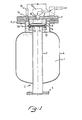
- This object of the invention is achieved with an air cannon according to the invention, by, that on the bottom of the second tube more or less concentric to the afore mentioned tubes, a third tube with a smaller diameter and shorter than the second tube is airtightly fastened on it with the one end of such a length, that between the ends of the first tube and the third tube, there is a space left inside the second tube, wherein a disk is placed, which near the circumference is provided with two collars, which project to both sides and stand some-what slanting outward, so that the disk can be moved back and forth between the ends of the first and the second tubes.
- the second tube is fastened on a flange, which forms the bottom of this tube and which flange can be airtightly fastened to a flange of the pressure vessel.
- the inlet opening through which the pressure tank is filled with air, is made in the flange; naturally, it is also possible to bring on this opening directly in the wall of the pressure tank or as is generally done at present in the wall of the second tube, whereby this opening has been placed such that, at the moment that the piston blocks the outlet opening, the openings via the in and outlet opening in the bottom of the third tube let through the air to pressure vessel, while if the outlet opening is opened and the disk is placed in the other end position that then the openings in the wall of the second tubular part do not stand in communication with the in and outlet opening in the bottom of the second tube.
- the disk is preferably made out of a metal disk covered by rubber or plastic sheet; the collars are also made of rubber or plastic whereby these are somewhat resilient.
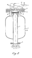
- the figures 1 and 2 show the same air cannon according to the invention with a valve in two different positions.
- the air cannon comprises a pressure tank 1 with an outlet opening 2 for the air from the pressure tank 1.
- the outlet opening consist of a first tube 3, which is airtightly fastened in the wall 4 of the pressure tank 1.
- a flange 5 is fastened in the wall 4 at the end of the tube for easy dismounting of the air cannon on a silo.
- This air cannon according to the invention has a flange 6, whereon a flanged branche 7 is fastened.
- On the flanged branche is airtightly welded a second tube 8 and concentric in the second tube 8 a third tube 9 of which the diameter is smaller and the length shorter than of the second tube 8.
- the diameter of the second tube 8 is larger than the diameter of the first tube 3.
- the first tube 3 and the third tube 9 are almost in line of each other and between the both ends of the first tube 3 and the third tube 9 is a space, wherein a valve 10 is placed.
- the disk is here made out of a metal inner disk 11 covered with a rubber jacket 12.
- the rubber jacket 12 has two rubber collars 13, 14, which slant outward to both sides.
- the outer diameter of the disk with rubber jacket and collars corresponds approximately with the inner diameter of the second tube 8.
- In the flange concentric to the tubes is an in and outlet opening or orifice 15.
- In the flange 7 is also a second inlet opening 16 for air, through which the pressure tank can be directely filled with air. Via a threeway valve 17 and a non return valve 18, which are mounted on the inlet opening 16, the pressure tank 1 can be filled with air under pressure.
- the air cannon can be filed again with air under pressure resetting the threeway valve in the filling position and so the valve brought back into the begin position.
- the wall of the tubular part 8 along which the disk 10 glides also need not to be made accurate and can be manufactured of normal commercial quality seamless steel tube, what makes all kinds of costly aperations, such as grinding unnecessary.
- the inner wall of the tubular part 8 can possibly be provided with a high quality plastic coating.
- small holes can be made in the wall of the collar 14 of the disk 10, through which the air enclosed by the space bounded by the tubular part 8 and the flange 7 can flow to the space bounded by the two collars 13, 14 of the disk 10. Through this it is possibly to fill the pressure tank directly instead through the supplier 18. If the disk has been brought into position by the high pressure, so that the outlet opening of the pressure tank is closed, the air can flow through the small holes to the space in between the collars 13, 14 and then past the collar 13 into the pressure tank 1. By the firing of the air cannon, the collar 13 will then be pressed against the wall of the tubular part 8 and through this the air will not be able to flow back to the quick air releaser.
- the small holes will preferably be made in the collar near the point where this is fastened to the disk.
Landscapes
- Engineering & Computer Science (AREA)
- Mechanical Engineering (AREA)
- Filling Or Discharging Of Gas Storage Vessels (AREA)
- Catching Or Destruction (AREA)
- Air Transport Of Granular Materials (AREA)
- Control Of Fluid Pressure (AREA)
- Physical Or Chemical Processes And Apparatus (AREA)
- Respiratory Apparatuses And Protective Means (AREA)
Priority Applications (1)
| Application Number | Priority Date | Filing Date | Title |
|---|---|---|---|
| AT86200896T ATE47113T1 (de) | 1985-05-24 | 1986-05-22 | Luftstossgeraet. |
Applications Claiming Priority (2)
| Application Number | Priority Date | Filing Date | Title |
|---|---|---|---|
| NL8501483 | 1985-05-24 | ||
| NL8501483A NL8501483A (nl) | 1985-05-24 | 1985-05-24 | Luchtstootapparaat. |
Publications (2)
| Publication Number | Publication Date |
|---|---|
| EP0202720A1 true EP0202720A1 (fr) | 1986-11-26 |
| EP0202720B1 EP0202720B1 (fr) | 1989-10-11 |
Family
ID=19846032
Family Applications (1)
| Application Number | Title | Priority Date | Filing Date |
|---|---|---|---|
| EP86200896A Expired EP0202720B1 (fr) | 1985-05-24 | 1986-05-22 | Canon à air |
Country Status (9)
| Country | Link |
|---|---|
| US (1) | US4703869A (fr) |
| EP (1) | EP0202720B1 (fr) |
| JP (1) | JPS62182087A (fr) |
| AT (1) | ATE47113T1 (fr) |
| AU (1) | AU580414B2 (fr) |
| CA (1) | CA1298248C (fr) |
| DE (1) | DE3666211D1 (fr) |
| NL (1) | NL8501483A (fr) |
| ZA (1) | ZA863778B (fr) |
Cited By (6)
| Publication number | Priority date | Publication date | Assignee | Title |
|---|---|---|---|---|
| EP0324368A1 (fr) * | 1988-01-05 | 1989-07-19 | AGRICHEMA Materialflusstechnik GmbH | Appareil pour impulsions d'air éliminant les formations du pont par matières en vrac dans les silos et autres choses semblables |
| EP0423572A1 (fr) * | 1989-10-20 | 1991-04-24 | Hosch-Company | Dispositif pour la production d'une onde de pression |
| WO1999018012A1 (fr) * | 1997-10-02 | 1999-04-15 | Agrichema Materialflusstechnik Gmbh | Dispositif de type canon a air comprime pour eviter la formation d'amas de materiau dans des produits en vrac situes dans des cuves de reaction et procede correspondant |
| DE10101041A1 (de) * | 2001-01-11 | 2002-07-25 | Agrilux Beteilungs Gmbh | Ventileinheit für eine Vorrichtung zum stoßartigen Ausblasen von Druckluft aus einem Druckluftspeicherbehälter zur Beseitigung von Materialanbackungen und -aufstauungen |
| US7837062B2 (en) | 2006-03-10 | 2010-11-23 | Martin Engineering Company | Air cannon for removal of flowable material from a material handling system |
| CN104828412A (zh) * | 2015-05-13 | 2015-08-12 | 濮阳市鸿宇压力容器有限公司 | 用于空气炮罐体的密封检测装置 |
Families Citing this family (19)
| Publication number | Priority date | Publication date | Assignee | Title |
|---|---|---|---|---|
| DE4236896A1 (de) * | 1992-10-31 | 1994-05-05 | Maury Hans Dietmar | Luftkanone zur Beseitigung von Schüttgutanbackungen und -stauungen |
| US5853160A (en) * | 1997-12-23 | 1998-12-29 | Martin Engineering Company | Aerator valve assembly |
| US6325605B1 (en) | 1998-11-02 | 2001-12-04 | Owens Corning Canada Inc. | Apparatus to control the dispersion and deposition of chopped fibrous strands |
| US6321939B1 (en) | 2001-02-06 | 2001-11-27 | Global Mfg. Inc. | High stress blast aerator with dampended piston |
| US6749528B2 (en) * | 2001-10-09 | 2004-06-15 | Wilson S. Wengert | Apparatus and method for playing golf using a ball launcher |
| US6644294B2 (en) | 2001-11-09 | 2003-11-11 | Robert N. Christensen | Air cannon |
| US6726059B2 (en) | 2002-01-16 | 2004-04-27 | Global Manufacturing Inc. | Quick release trigger valve and blast aerator |
| US6702248B2 (en) * | 2002-01-16 | 2004-03-09 | Global Manufacturing, Inc. | Blast aerator with springless, pneumatically dampened actuator |
| DE602005020375D1 (de) * | 2004-01-14 | 2010-05-20 | Martin Eng Co | Druckbetriebene Belüftungsventilanordnung |
| US7409794B2 (en) | 2004-09-20 | 2008-08-12 | Daniel Triano | Fishing line casting and bait projectile system |
| JP2006282083A (ja) * | 2005-04-01 | 2006-10-19 | Denso Corp | 車両用空気質成分供給装置 |
| JP2006282082A (ja) * | 2005-04-01 | 2006-10-19 | Denso Corp | 車両用空気砲発生装置 |
| US20070209648A1 (en) * | 2006-03-10 | 2007-09-13 | Martin Engineering Company | Air cannon for removal of flowable material from a material handling system |
| US20080121220A1 (en) * | 2006-11-28 | 2008-05-29 | Disney Enterprises, Inc. | Device for producing high speed air projectiles or pulses |
| CN103363292B (zh) * | 2013-07-22 | 2015-04-08 | 广州龙之杰科技有限公司 | 可精确控制的分气气罐装置 |
| US9650206B2 (en) * | 2015-07-24 | 2017-05-16 | Dynamic Aur Inc. | Conveying systems |
| WO2018235099A1 (fr) * | 2017-06-20 | 2018-12-27 | Thejo Engineering Ltd. | Jet d'air |
| US11117740B2 (en) * | 2018-04-30 | 2021-09-14 | Global Mfg. Inc. | Externally controlled aerator control module and blast aerator equipped therewith |
| US10737877B2 (en) * | 2018-04-30 | 2020-08-11 | Global Manufacturing Inc. | Externally controlled retrofittable aerator control module and blast aerator equipped therewith |
Citations (1)
| Publication number | Priority date | Publication date | Assignee | Title |
|---|---|---|---|---|
| FR2547639A1 (fr) * | 1983-06-15 | 1984-12-21 | Simoens Herve | Piston de valve d'alimentation d'une capacite puis de decharge brutale de cette capacite et valve de decharge brutale pourvue de ce piston |
Family Cites Families (3)
| Publication number | Priority date | Publication date | Assignee | Title |
|---|---|---|---|---|
| US2627873A (en) * | 1949-06-20 | 1953-02-10 | Edward F Bothe | Flush valve |
| US3788527A (en) * | 1973-01-22 | 1974-01-29 | Martin Eng Co | Quick-release aerator for introducing high pressure air into a container to facilitate dispensing |
| FR2459188A1 (fr) * | 1979-06-19 | 1981-01-09 | Ermap | Dispositif d'aeration par decharge brusque d'air comprime |
-
1985
- 1985-05-24 NL NL8501483A patent/NL8501483A/nl not_active Application Discontinuation
-
1986
- 1986-05-21 JP JP61118351A patent/JPS62182087A/ja active Pending
- 1986-05-21 ZA ZA863778A patent/ZA863778B/xx unknown
- 1986-05-22 AT AT86200896T patent/ATE47113T1/de not_active IP Right Cessation
- 1986-05-22 DE DE8686200896T patent/DE3666211D1/de not_active Expired
- 1986-05-22 EP EP86200896A patent/EP0202720B1/fr not_active Expired
- 1986-05-22 AU AU57697/86A patent/AU580414B2/en not_active Ceased
- 1986-05-23 CA CA000509851A patent/CA1298248C/fr not_active Expired - Fee Related
- 1986-05-27 US US06/868,365 patent/US4703869A/en not_active Expired - Fee Related
Patent Citations (1)
| Publication number | Priority date | Publication date | Assignee | Title |
|---|---|---|---|---|
| FR2547639A1 (fr) * | 1983-06-15 | 1984-12-21 | Simoens Herve | Piston de valve d'alimentation d'une capacite puis de decharge brutale de cette capacite et valve de decharge brutale pourvue de ce piston |
Cited By (8)
| Publication number | Priority date | Publication date | Assignee | Title |
|---|---|---|---|---|
| EP0324368A1 (fr) * | 1988-01-05 | 1989-07-19 | AGRICHEMA Materialflusstechnik GmbH | Appareil pour impulsions d'air éliminant les formations du pont par matières en vrac dans les silos et autres choses semblables |
| EP0423572A1 (fr) * | 1989-10-20 | 1991-04-24 | Hosch-Company | Dispositif pour la production d'une onde de pression |
| AU625447B2 (en) * | 1989-10-20 | 1992-07-09 | Hosch-Company | Device for the intermittant release of a shock wave |
| WO1999018012A1 (fr) * | 1997-10-02 | 1999-04-15 | Agrichema Materialflusstechnik Gmbh | Dispositif de type canon a air comprime pour eviter la formation d'amas de materiau dans des produits en vrac situes dans des cuves de reaction et procede correspondant |
| DE10101041A1 (de) * | 2001-01-11 | 2002-07-25 | Agrilux Beteilungs Gmbh | Ventileinheit für eine Vorrichtung zum stoßartigen Ausblasen von Druckluft aus einem Druckluftspeicherbehälter zur Beseitigung von Materialanbackungen und -aufstauungen |
| DE10101041B4 (de) * | 2001-01-11 | 2014-09-18 | Agrilux Beteiligungs Gmbh | Ventileinheit für eine Vorrichtung zum stoßartigen Ausblasen von Druckluft aus einem Druckluftspeicherbehälter zur Beseitigung von Materialanbackungen und -aufstauungen |
| US7837062B2 (en) | 2006-03-10 | 2010-11-23 | Martin Engineering Company | Air cannon for removal of flowable material from a material handling system |
| CN104828412A (zh) * | 2015-05-13 | 2015-08-12 | 濮阳市鸿宇压力容器有限公司 | 用于空气炮罐体的密封检测装置 |
Also Published As
| Publication number | Publication date |
|---|---|
| CA1298248C (fr) | 1992-03-31 |
| NL8501483A (nl) | 1986-12-16 |
| ATE47113T1 (de) | 1989-10-15 |
| JPS62182087A (ja) | 1987-08-10 |
| DE3666211D1 (en) | 1989-11-16 |
| US4703869A (en) | 1987-11-03 |
| AU5769786A (en) | 1986-11-27 |
| EP0202720B1 (fr) | 1989-10-11 |
| ZA863778B (en) | 1986-12-30 |
| AU580414B2 (en) | 1989-01-12 |
Similar Documents
| Publication | Publication Date | Title |
|---|---|---|
| EP0202720A1 (fr) | Canon à air | |
| US3158296A (en) | Fluid storage and discharge apparatus | |
| US3788527A (en) | Quick-release aerator for introducing high pressure air into a container to facilitate dispensing | |
| US5133853A (en) | Sewage system | |
| US4413755A (en) | Metered aerosol valve for use in inverted position | |
| US5163485A (en) | Container assembly for flowable materials | |
| US3705667A (en) | Proportioning valve for a pressurized dispenser | |
| AU618629B2 (en) | Press-out gun for double chamber cartridges | |
| US5143256A (en) | Gas accumulator and blaster apparatus | |
| US3244328A (en) | Dispensing from plural sources | |
| US4051982A (en) | Fast release aerator for materials handling | |
| BG64045B1 (bg) | Устройство за дозиране на течност под налягане | |
| US3067810A (en) | Bladder fuel tank | |
| CZ229993A3 (en) | Air gun for removing excessive and clogging loose material | |
| NO151797C (no) | Apparat for toemming av beholdere hvori gass er lagret opploest under trykk i et opploesningsmiddel | |
| US2501611A (en) | Portable dispensing drum and method of refilling | |
| US4445629A (en) | Container filling machine product dispensing cylinder | |
| CN1003996B (zh) | 液体灌装设备 | |
| US20230294906A1 (en) | Method For Emptying Viscous Material Out Of A Cartridge That Is Open At Both Ends | |
| US6561222B1 (en) | Container for fluids | |
| SU917692A3 (ru) | Цистерна дл сыпучих материалов | |
| JP5785784B2 (ja) | 消火剤原液貯蔵タンクおよび消火剤混合装置 | |
| US2437618A (en) | Beer delivery and dispensing apparatus | |
| PL195402B1 (pl) | Sposób i urządzenie do transportu materiału sypkiego do urządzenia odbiorczego | |
| US3239101A (en) | Gas charging apparatus with check valve |
Legal Events
| Date | Code | Title | Description |
|---|---|---|---|
| PUAI | Public reference made under article 153(3) epc to a published international application that has entered the european phase |
Free format text: ORIGINAL CODE: 0009012 |
|
| AK | Designated contracting states |
Kind code of ref document: A1 Designated state(s): AT BE CH DE FR GB IT LI LU NL SE |
|
| 17P | Request for examination filed |
Effective date: 19861223 |
|
| 17Q | First examination report despatched |
Effective date: 19870916 |
|
| GRAA | (expected) grant |
Free format text: ORIGINAL CODE: 0009210 |
|
| AK | Designated contracting states |
Kind code of ref document: B1 Designated state(s): AT BE CH DE FR GB IT LI LU NL SE |
|
| REF | Corresponds to: |
Ref document number: 47113 Country of ref document: AT Date of ref document: 19891015 Kind code of ref document: T |
|
| REF | Corresponds to: |
Ref document number: 3666211 Country of ref document: DE Date of ref document: 19891116 |
|
| ITF | It: translation for a ep patent filed | ||
| ET | Fr: translation filed | ||
| PLBE | No opposition filed within time limit |
Free format text: ORIGINAL CODE: 0009261 |
|
| STAA | Information on the status of an ep patent application or granted ep patent |
Free format text: STATUS: NO OPPOSITION FILED WITHIN TIME LIMIT |
|
| 26N | No opposition filed | ||
| ITTA | It: last paid annual fee | ||
| EPTA | Lu: last paid annual fee | ||
| EAL | Se: european patent in force in sweden |
Ref document number: 86200896.8 |
|
| PGFP | Annual fee paid to national office [announced via postgrant information from national office to epo] |
Ref country code: SE Payment date: 19980423 Year of fee payment: 13 Ref country code: GB Payment date: 19980423 Year of fee payment: 13 |
|
| PGFP | Annual fee paid to national office [announced via postgrant information from national office to epo] |
Ref country code: CH Payment date: 19980501 Year of fee payment: 13 |
|
| PGFP | Annual fee paid to national office [announced via postgrant information from national office to epo] |
Ref country code: AT Payment date: 19980526 Year of fee payment: 13 |
|
| PGFP | Annual fee paid to national office [announced via postgrant information from national office to epo] |
Ref country code: FR Payment date: 19980529 Year of fee payment: 13 |
|
| PGFP | Annual fee paid to national office [announced via postgrant information from national office to epo] |
Ref country code: LU Payment date: 19980604 Year of fee payment: 13 |
|
| PGFP | Annual fee paid to national office [announced via postgrant information from national office to epo] |
Ref country code: BE Payment date: 19980707 Year of fee payment: 13 |
|
| PG25 | Lapsed in a contracting state [announced via postgrant information from national office to epo] |
Ref country code: LU Free format text: LAPSE BECAUSE OF NON-PAYMENT OF DUE FEES Effective date: 19990522 Ref country code: GB Free format text: LAPSE BECAUSE OF NON-PAYMENT OF DUE FEES Effective date: 19990522 Ref country code: AT Free format text: LAPSE BECAUSE OF NON-PAYMENT OF DUE FEES Effective date: 19990522 |
|
| PG25 | Lapsed in a contracting state [announced via postgrant information from national office to epo] |
Ref country code: SE Free format text: LAPSE BECAUSE OF NON-PAYMENT OF DUE FEES Effective date: 19990523 |
|
| PG25 | Lapsed in a contracting state [announced via postgrant information from national office to epo] |
Ref country code: LI Free format text: LAPSE BECAUSE OF NON-PAYMENT OF DUE FEES Effective date: 19990531 Ref country code: CH Free format text: LAPSE BECAUSE OF NON-PAYMENT OF DUE FEES Effective date: 19990531 Ref country code: BE Free format text: LAPSE BECAUSE OF NON-PAYMENT OF DUE FEES Effective date: 19990531 |
|
| BERE | Be: lapsed |
Owner name: TECHNISCH BUREAU KNOL B.V. Effective date: 19990531 |
|
| REG | Reference to a national code |
Ref country code: CH Ref legal event code: PL |
|
| GBPC | Gb: european patent ceased through non-payment of renewal fee |
Effective date: 19990522 |
|
| EUG | Se: european patent has lapsed |
Ref document number: 86200896.8 |
|
| PG25 | Lapsed in a contracting state [announced via postgrant information from national office to epo] |
Ref country code: FR Free format text: LAPSE BECAUSE OF NON-PAYMENT OF DUE FEES Effective date: 20000131 |
|
| REG | Reference to a national code |
Ref country code: FR Ref legal event code: ST |
|
| NLS | Nl: assignments of ep-patents |
Owner name: AIR-O-BLAST B.V. |
|
| PG25 | Lapsed in a contracting state [announced via postgrant information from national office to epo] |
Ref country code: IT Free format text: LAPSE BECAUSE OF NON-PAYMENT OF DUE FEES;WARNING: LAPSES OF ITALIAN PATENTS WITH EFFECTIVE DATE BEFORE 2007 MAY HAVE OCCURRED AT ANY TIME BEFORE 2007. THE CORRECT EFFECTIVE DATE MAY BE DIFFERENT FROM THE ONE RECORDED. Effective date: 20050522 |
|
| PGFP | Annual fee paid to national office [announced via postgrant information from national office to epo] |
Ref country code: NL Payment date: 20050531 Year of fee payment: 20 |
|
| PGFP | Annual fee paid to national office [announced via postgrant information from national office to epo] |
Ref country code: DE Payment date: 20050728 Year of fee payment: 20 |
|
| NLS | Nl: assignments of ep-patents |
Owner name: AIR-O-BLAST GMBH Effective date: 20050727 |
|
| PG25 | Lapsed in a contracting state [announced via postgrant information from national office to epo] |
Ref country code: NL Free format text: LAPSE BECAUSE OF EXPIRATION OF PROTECTION Effective date: 20060522 |
|
| NLV7 | Nl: ceased due to reaching the maximum lifetime of a patent |
Effective date: 20060522 |