EP0202206A1 - Robot - Google Patents
Robot Download PDFInfo
- Publication number
- EP0202206A1 EP0202206A1 EP86850120A EP86850120A EP0202206A1 EP 0202206 A1 EP0202206 A1 EP 0202206A1 EP 86850120 A EP86850120 A EP 86850120A EP 86850120 A EP86850120 A EP 86850120A EP 0202206 A1 EP0202206 A1 EP 0202206A1
- Authority
- EP
- European Patent Office
- Prior art keywords
- arm
- robot according
- universal joint
- joint
- frame
- Prior art date
- Legal status (The legal status is an assumption and is not a legal conclusion. Google has not performed a legal analysis and makes no representation as to the accuracy of the status listed.)
- Granted
Links
Images


Classifications
-
- B—PERFORMING OPERATIONS; TRANSPORTING
- B25—HAND TOOLS; PORTABLE POWER-DRIVEN TOOLS; MANIPULATORS
- B25J—MANIPULATORS; CHAMBERS PROVIDED WITH MANIPULATION DEVICES
- B25J17/00—Joints
- B25J17/02—Wrist joints
- B25J17/0258—Two-dimensional joints
- B25J17/0266—Two-dimensional joints comprising more than two actuating or connecting rods
-
- B—PERFORMING OPERATIONS; TRANSPORTING
- B25—HAND TOOLS; PORTABLE POWER-DRIVEN TOOLS; MANIPULATORS
- B25J—MANIPULATORS; CHAMBERS PROVIDED WITH MANIPULATION DEVICES
- B25J17/00—Joints
- B25J17/02—Wrist joints
- B25J17/0258—Two-dimensional joints
- B25J17/0275—Universal joints, e.g. Hooke, Cardan, ball joints
-
- B—PERFORMING OPERATIONS; TRANSPORTING
- B25—HAND TOOLS; PORTABLE POWER-DRIVEN TOOLS; MANIPULATORS
- B25J—MANIPULATORS; CHAMBERS PROVIDED WITH MANIPULATION DEVICES
- B25J9/00—Programme-controlled manipulators
- B25J9/003—Programme-controlled manipulators having parallel kinematics
- B25J9/0063—Programme-controlled manipulators having parallel kinematics with kinematics chains having an universal joint at the base
- B25J9/0069—Programme-controlled manipulators having parallel kinematics with kinematics chains having an universal joint at the base with kinematics chains of the type universal-prismatic-universal
Definitions
- the present invention relates to a robot comprising at least three setting devices which can be lengthened or shortened in longitudinal direction, each setting device being secured via a first joint in a fixed frame enabling each setting device to pivot freely in relation to the frame and one end or each setting device being attached via a second joint in a movable positioning head, and an intermediate arm extending from the positioning head and located between the setting devices.
- Such a robot is already known through No-B-148 216, for example.
- the intermediate arm intended to carry load, is here displaceable in a cylinder which is in turn jointed to a frame.
- this arrangement can only move relatively low loads since the intermediate arm is inclined with respect to the cylinder when a load is applied.
- the positioning head is moved with the aid of setting devices so that the arm is displaced in the cylinder the arm will, due to this inclination, become nipped in the cylinder if heavy loads are applied. This will either prevent further movement of the positioning head or give rise to considerable, damaging vibrations.
- This known robot is therefore only suitable for moving very small loads and even then, because of the clearance required between pistion and cylinder and the poor radial control between these elements, the setting accuracy of the robot is extremely low. Furthermore, the robot can only turn the load a limited extent, the turning angle being limited by the setting devices coming into contact with each other.
- the object of the invention is to eliminate the drawbacks of the known arrangement, thus enabling even relatively large loads to be moved with great positioning accuracy and turned at an arbitrary angle.
- the frame supports a universal joint comprising a central through-hole having a cross section somewhat greater than that of the arm and wherein the arm extends through the central opening of the universal joint so that said arm can, while still maintaining radial control, be moved in axial direction and set at different angles in relation to the frame.
- the robot in the first example shown in Figures I - 3 comprises three setting devices 1, each being in the form of a piston 2 movable in a cylinder 3.
- the piston is moved in the cylinder by conventional drive means, not shown. These may be hydraulic or pneumatic means or consist of a nut and bolt mechanism or hydraulic fluid.
- Each cylinder end is secured via a joint 4 to a fixed frame or stand 5.
- the joint 4, enabling the cylinder 3 and piston 2 to pivot in all directions in relation to the frame 5, is shown here as a cardan joint but may comprise any suitable universal joint.
- Each piston 2 is connected via a similar joint 6 to a positioning head 7.
- the setting devices are arranged along the sides of an imiginary triangular pyramid and the positioning head 7 is set exactly in the desired position by moving the pistons 2 in respective cylinders 3, since the effective length of the setting devices clearly defines the location of the positioning head.
- the robot includes a control system, not shown, which emits signals to the setting devices causing the positioning head to move to the desired position.
- the sleeve is rigidly connected to the positioning head and has two bearings at each end, the shaft 9 being pivotably journalled in these bearings.
- a universal joint 11 is secured to the frame 5 in an area located along the axis of symmetry of the imagined pyramid.
- the universal joint 11 has a central opening, with a cross section somewhat greater than the outer diameter of the sleeve 10.
- the sleeve extends through the central opening of the universal joint and can be displaced in axial direction in relation to the frame and the joint, while at the same time it can be set at an arbitrary angle in relation to the frame. The sleeve is thus controlled radially and is locked against turning in the joint.
- the sleeve 10 is sufficiently long to allow it always to be in the central opening of the universal joint 11 throughout the entire range of movement of the positioning head 7.
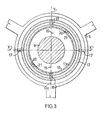
- the universal joint 11 consists of an outer ring 12 and an inner ring 13.
- the outer ring 12 is attached in the frame 5 by means of two swivel pins 17 and can swing around the axis x-x formed by the pins.
- the inner ring is secured in the outer ring 12 by two shaft pins 18 and can swing around an axis y-y perpendicular to the axis x-x of the outer ring.
- the diameter of the inner diameter of the inner ring is slightly larger than the outer diameter of the sleeve.
- the sleeve 10 is prevented from turning in joint 11 by axial grooves 20 into which shaft pins 21 protruding radially from the inner ring 13 and secured thereto are guided.
- the construction of the universal joint is not decisive for the invention and it may comprise a ball-and-socket joint for instance.
- the sleeve 10 supports a torque motor, not shown, the turning movement being arranged by means of a suitable transmission 14, such as the chain gear shown in the drawings, to transmit a desired turning movement to the shaft 9.
- the shaft end protruding through the positioning head 7 is provided with a suitable manipulating means consisting, for instance, of a motor-operated gripping device 19.
- the gripping movement of the device can then be controlled with the aid of operating rods 15, 16 protruding above the top end of the sleeve 10.
- Each joint 24, which in the embodiment shown in Figure 4, pivotally connects a setting element 1 to the frame 5, consists of a fork-shaped member, comprising an U-shaped portion 25, consisting of two parallell legs 26, 27 and a connecting portion 28 joining the two legs 26, 27 to each other.
- a shaft pivot 29 extends from the connecting portion in the opposite direction to the legs. Said shaft pivot 29 is rotatably mounted in a hole provided in the frame 5 and axially fixed relative to the frame 5.
- each leg 26, 27 a hole is provided for a pivot pin 30 rigidly connected to the cylinder 3.
- the two pivot pins 30 provided on each cylinder 3 and the two holes in each couple of legs 26, 27 form a pivot axis for the corresponding setting device 1.
- Said pivot axis is perpendicular to the axes of rotation of the joint 24 relative to the frame 5.
- Said pivot pins are distant from the end portion of the cylinder 3.
- the motors are arranged at the end portions of the setting devices 1. Further, range of movement 31 of the robot is shown in Figure 4 with broken lines.
- the arm 8 arranged between the setting devices 1 consists of a shaft and sleeve unit, but it could also consist of a single shaft journalled in the universal joint and in the positioning head 7. Furthermore, there may be more than the three setting devices shown in the drawings. Neither need they be arranged symmetrically around the arm 8.
- the locking means preventing turning between the sleeve 10 and the inner ring 13 may also be designed in several different ways. There might, for instance, be a number of guides in the form of ball guides. Furthermore, the axial grooves might be provided in the universal joint 11 instead of in the sleeve 10, in which case the sleeve would be provided with radially protruding guide means.
- the shaft 9 may also be displaceable in the sleeve 10.
Priority Applications (1)
| Application Number | Priority Date | Filing Date | Title |
|---|---|---|---|
| AT86850120T ATE50720T1 (de) | 1985-05-10 | 1986-04-09 | Roboter. |
Applications Claiming Priority (2)
| Application Number | Priority Date | Filing Date | Title |
|---|---|---|---|
| SE8502327 | 1985-05-10 | ||
| SE8502327A SE452279B (sv) | 1985-05-10 | 1985-05-10 | Robot |
Publications (2)
| Publication Number | Publication Date |
|---|---|
| EP0202206A1 true EP0202206A1 (fr) | 1986-11-20 |
| EP0202206B1 EP0202206B1 (fr) | 1990-03-07 |
Family
ID=20360168
Family Applications (1)
| Application Number | Title | Priority Date | Filing Date |
|---|---|---|---|
| EP86850120A Expired - Lifetime EP0202206B1 (fr) | 1985-05-10 | 1986-04-09 | Robot |
Country Status (13)
| Country | Link |
|---|---|
| US (1) | US4732525A (fr) |
| EP (1) | EP0202206B1 (fr) |
| JP (1) | JPH0725045B2 (fr) |
| AT (1) | ATE50720T1 (fr) |
| AU (1) | AU580152B2 (fr) |
| BR (1) | BR8602101A (fr) |
| CA (1) | CA1253534A (fr) |
| DE (1) | DE3669278D1 (fr) |
| DK (1) | DK167603B1 (fr) |
| ES (1) | ES8704374A1 (fr) |
| FI (1) | FI81514C (fr) |
| NO (1) | NO160422C (fr) |
| SE (1) | SE452279B (fr) |
Cited By (12)
| Publication number | Priority date | Publication date | Assignee | Title |
|---|---|---|---|---|
| US4776749A (en) * | 1986-03-25 | 1988-10-11 | Northrop Corporation | Robotic device |
| US4801239A (en) * | 1985-11-26 | 1989-01-31 | Multi Craft A.S. | Arm device |
| US5028180A (en) * | 1989-09-01 | 1991-07-02 | Sheldon Paul C | Six-axis machine tool |
| US5388935A (en) * | 1993-08-03 | 1995-02-14 | Giddings & Lewis, Inc. | Six axis machine tool |
| US5538373A (en) * | 1992-02-20 | 1996-07-23 | Giddings & Lewis, Inc. | Machine tool vibration isolation system |
| WO1997030826A1 (fr) * | 1996-02-20 | 1997-08-28 | Neos Robotics Ab | Systeme de positionnement pour operation de production |
| US5940180A (en) * | 1994-10-11 | 1999-08-17 | Giddings & Lewis | Laser interferometer measurement system for use with machine tools |
| US6059703A (en) * | 1996-01-03 | 2000-05-09 | Heisel; Uwe | Device with at least one movement unit |
| DE102008023069A1 (de) * | 2008-05-09 | 2009-11-12 | Multivac Sepp Haggenmüller Gmbh & Co. Kg | Handhabungsvorrichtung zur Positionierung von Produkten mit einem drehmomentübertragenden Verbindungselement |
| CN102320041A (zh) * | 2011-08-17 | 2012-01-18 | 中国农业大学 | 三自由度混联机械臂 |
| CN104985596A (zh) * | 2015-07-09 | 2015-10-21 | 天津大学 | 一种含多轴转动支架的五自由度混联机器人 |
| DE102012207178B4 (de) | 2012-04-30 | 2018-06-14 | Fgb A. Steinbach Gmbh & Co. Kg | Hydraulikzylinder für Hexapod und Hexapod mit einem solchen Hydraulikzylinder |
Families Citing this family (42)
| Publication number | Priority date | Publication date | Assignee | Title |
|---|---|---|---|---|
| US4785528A (en) * | 1986-12-22 | 1988-11-22 | The Boeing Company | Robotic work positioning system |
| FR2628670B1 (fr) * | 1988-03-21 | 1990-08-17 | Inst Nat Rech Inf Automat | Dispositif articule, notamment utilisable dans le domaine de la robotique |
| DE4221052A1 (de) * | 1992-06-30 | 1994-01-05 | Focke & Co | Vorrichtung zum Handhaben von Bobinen aus Materialbahnen |
| US5585707A (en) * | 1994-02-28 | 1996-12-17 | Mcdonnell Douglas Corporation | Tendon suspended platform robot |
| US5813287A (en) * | 1994-03-02 | 1998-09-29 | Renishaw Plc | Coordinate positioning machine |
| US6121743A (en) * | 1996-03-22 | 2000-09-19 | Genmark Automation, Inc. | Dual robotic arm end effectors having independent yaw motion |
| US5789890A (en) * | 1996-03-22 | 1998-08-04 | Genmark Automation | Robot having multiple degrees of freedom |
| US5954840A (en) * | 1996-06-13 | 1999-09-21 | Genmark Automation | Universally tiltable Z axis drive arm |
| US5738481A (en) * | 1996-12-02 | 1998-04-14 | Rogers; Vincent | Universally actuable robot assembly |
| US5993142A (en) * | 1997-07-10 | 1999-11-30 | Genmark Automation, Inc. | Robot having multiple degrees of freedom in an isolated environment |
| SE512338C2 (sv) | 1998-06-25 | 2000-02-28 | Neos Robotics Ab | System och metod för reglering av en robot |
| US6489741B1 (en) | 1998-08-25 | 2002-12-03 | Genmark Automation, Inc. | Robot motion compensation system |
| JP3806273B2 (ja) | 1999-09-17 | 2006-08-09 | 株式会社ジェイテクト | 四自由度パラレルロボット |
| JP4632560B2 (ja) | 2000-03-01 | 2011-02-16 | シーグ パック システムズ アクチェンゲゼルシャフト | 三次元空間内で製品を操作するロボット |
| ES2205970B1 (es) * | 2001-05-10 | 2005-07-16 | Fundacion Fatronik | Sistema cinematico para cabezal de maquina. |
| US6557235B1 (en) | 2002-03-06 | 2003-05-06 | The Regents Of The University Of Michigan | Bi-axial coplanar apparatus |
| CN100446940C (zh) * | 2003-09-16 | 2008-12-31 | 天津大学 | 非对称空间5自由度混联机器人 |
| SE525668C2 (sv) * | 2003-10-02 | 2005-03-29 | Parallel Kinematics Machines S | Led till ett lagrat ställdon lagrat kring ett wobbelorgan |
| US20050072655A1 (en) * | 2003-10-03 | 2005-04-07 | Glen Raque | Transport system |
| ES2255386B1 (es) * | 2004-05-13 | 2007-10-01 | Loxin 2002, S.L. | Sistema mejorado de remachado automatico. |
| US20060032192A1 (en) * | 2004-08-13 | 2006-02-16 | Mcleod Jesse | Transporter device |
| SE527873C2 (sv) * | 2004-11-18 | 2006-07-04 | Exechon Ab | Parallellkinematisk maskin |
| US20090199610A1 (en) * | 2005-04-06 | 2009-08-13 | Kikuchi Seisakusho Co., Ltd. | Actuator, parallel link mechanism using the same, and long material bending device |
| US20060241810A1 (en) * | 2005-04-20 | 2006-10-26 | Dan Zhang | High stiffness, high accuracy, parallel kinematic, three degree of freedom motion platform |
| CN100348375C (zh) * | 2005-07-11 | 2007-11-14 | 天津大学 | 五自由度机器人 |
| CN100348386C (zh) * | 2005-09-15 | 2007-11-14 | 天津大学 | 含冗余自由度的多坐标混联机器人 |
| CN100480003C (zh) * | 2007-04-20 | 2009-04-22 | 天津大学 | 五自由度混联机器人 |
| US9370867B2 (en) | 2009-08-04 | 2016-06-21 | Majatronic Gmbh | Parallel robot |
| SE0950953A1 (sv) * | 2009-12-11 | 2011-06-12 | Tetrafix Ab | Förbindningsanordning |
| SE535182C2 (sv) * | 2010-06-17 | 2012-05-08 | Exechon Ab | En parallellkinematisk maskin med kardanhållare |
| US7982951B1 (en) | 2010-11-08 | 2011-07-19 | Robert Innes | Digital tracking platform for telescopes |
| CN102601793B (zh) * | 2012-03-29 | 2014-04-09 | 天津大学 | 新型空间全对称四自由度并联机构 |
| CN102672708B (zh) * | 2012-05-18 | 2014-12-17 | 天津大学 | 一种多坐标混联机器人 |
| CN102699900B (zh) * | 2012-06-06 | 2015-05-27 | 天津大学 | 含双平台的过约束五自由度混联机器人 |
| CN103252771B (zh) * | 2013-05-07 | 2015-04-15 | 天津大学 | 一种非对称五自由度混联机器人 |
| CN104384941B (zh) * | 2014-09-16 | 2016-08-17 | 燕山大学 | 具有等效Tricept机构运动的过约束并联机构 |
| CN105058376B (zh) * | 2015-08-17 | 2017-03-01 | 天津大学 | 一种具有三对称运动学性能的过约束高刚度机器人 |
| WO2017070329A1 (fr) * | 2015-10-23 | 2017-04-27 | The Trustees Of The University Of Pennsylvania | Élément structural reconfigurable et système |
| CN105690165B (zh) * | 2016-02-03 | 2017-05-10 | 中北大学 | 一种大姿态角2r1t三自由度空间并联机构 |
| CN106473809B (zh) * | 2016-10-24 | 2023-11-14 | 北京华巍中兴电气有限公司 | 一种三自由度并联式无铰链手术机器人 |
| CN106426105B (zh) * | 2016-11-10 | 2019-09-17 | 中国地质大学(武汉) | 一种提升负载能力的2r两自由度并联机构 |
| JP7347892B2 (ja) * | 2019-09-18 | 2023-09-20 | 株式会社ダイヘン | 搬送ロボットおよびこれを備えたワーク搬送システム |
Citations (4)
| Publication number | Priority date | Publication date | Assignee | Title |
|---|---|---|---|---|
| GB2085399A (en) * | 1980-10-06 | 1982-04-28 | Simunovic Sergio N | Robotic manipulator |
| GB2088987A (en) * | 1980-11-12 | 1982-06-16 | Marconi Co Ltd | Drive Systems |
| EP0066393A2 (fr) * | 1981-05-15 | 1982-12-08 | Westinghouse Electric Corporation | Robot multi-bras |
| GB2143498A (en) * | 1983-07-21 | 1985-02-13 | Emi Ltd | Improvements in or relating to assembly robots |
Family Cites Families (3)
| Publication number | Priority date | Publication date | Assignee | Title |
|---|---|---|---|---|
| SU1083017A1 (ru) * | 1982-04-26 | 1984-03-30 | Институт Машиноведения Им.А.А.Благонравова | Пространственный механизм с шестью степен ми подвижности |
| US4569627A (en) * | 1983-03-10 | 1986-02-11 | Simunovic Sergio N | Robotic manipulator |
| US4790718A (en) * | 1985-03-27 | 1988-12-13 | The English Electric Company Plc | Manipulators |
-
1985
- 1985-05-10 SE SE8502327A patent/SE452279B/sv not_active IP Right Cessation
-
1986
- 1986-04-09 AT AT86850120T patent/ATE50720T1/de not_active IP Right Cessation
- 1986-04-09 EP EP86850120A patent/EP0202206B1/fr not_active Expired - Lifetime
- 1986-04-09 DE DE8686850120T patent/DE3669278D1/de not_active Expired - Lifetime
- 1986-04-11 NO NO861426A patent/NO160422C/no unknown
- 1986-04-11 DK DK164786A patent/DK167603B1/da not_active IP Right Cessation
- 1986-04-18 AU AU56349/86A patent/AU580152B2/en not_active Expired
- 1986-04-21 JP JP61090180A patent/JPH0725045B2/ja not_active Expired - Fee Related
- 1986-04-21 US US06/854,355 patent/US4732525A/en not_active Expired - Lifetime
- 1986-04-22 ES ES554253A patent/ES8704374A1/es not_active Expired
- 1986-04-29 CA CA000507867A patent/CA1253534A/fr not_active Expired
- 1986-05-06 FI FI861878A patent/FI81514C/fi not_active IP Right Cessation
- 1986-05-09 BR BR8602101A patent/BR8602101A/pt not_active IP Right Cessation
Patent Citations (4)
| Publication number | Priority date | Publication date | Assignee | Title |
|---|---|---|---|---|
| GB2085399A (en) * | 1980-10-06 | 1982-04-28 | Simunovic Sergio N | Robotic manipulator |
| GB2088987A (en) * | 1980-11-12 | 1982-06-16 | Marconi Co Ltd | Drive Systems |
| EP0066393A2 (fr) * | 1981-05-15 | 1982-12-08 | Westinghouse Electric Corporation | Robot multi-bras |
| GB2143498A (en) * | 1983-07-21 | 1985-02-13 | Emi Ltd | Improvements in or relating to assembly robots |
Cited By (19)
| Publication number | Priority date | Publication date | Assignee | Title |
|---|---|---|---|---|
| US4801239A (en) * | 1985-11-26 | 1989-01-31 | Multi Craft A.S. | Arm device |
| US4776749A (en) * | 1986-03-25 | 1988-10-11 | Northrop Corporation | Robotic device |
| US5028180A (en) * | 1989-09-01 | 1991-07-02 | Sheldon Paul C | Six-axis machine tool |
| US5354158A (en) * | 1989-09-01 | 1994-10-11 | Kearney & Trecker Corporation | Six axis machine tool |
| US5466085A (en) * | 1989-09-01 | 1995-11-14 | Giddings & Lewis, Inc. | Gimbal assembly for six axis machine tool |
| US5489168A (en) * | 1989-09-01 | 1996-02-06 | Giddings & Lewis | Metrology instrument arm system |
| US5538373A (en) * | 1992-02-20 | 1996-07-23 | Giddings & Lewis, Inc. | Machine tool vibration isolation system |
| US5388935A (en) * | 1993-08-03 | 1995-02-14 | Giddings & Lewis, Inc. | Six axis machine tool |
| US5940180A (en) * | 1994-10-11 | 1999-08-17 | Giddings & Lewis | Laser interferometer measurement system for use with machine tools |
| US6059703A (en) * | 1996-01-03 | 2000-05-09 | Heisel; Uwe | Device with at least one movement unit |
| WO1997030826A1 (fr) * | 1996-02-20 | 1997-08-28 | Neos Robotics Ab | Systeme de positionnement pour operation de production |
| US6043621A (en) * | 1996-02-20 | 2000-03-28 | Neos Robotics Ab | Production positioning system |
| DE102008023069A1 (de) * | 2008-05-09 | 2009-11-12 | Multivac Sepp Haggenmüller Gmbh & Co. Kg | Handhabungsvorrichtung zur Positionierung von Produkten mit einem drehmomentübertragenden Verbindungselement |
| CN102320041A (zh) * | 2011-08-17 | 2012-01-18 | 中国农业大学 | 三自由度混联机械臂 |
| CN102320041B (zh) * | 2011-08-17 | 2015-01-28 | 中国农业大学 | 三自由度混联机械臂 |
| DE102012207178B4 (de) | 2012-04-30 | 2018-06-14 | Fgb A. Steinbach Gmbh & Co. Kg | Hydraulikzylinder für Hexapod und Hexapod mit einem solchen Hydraulikzylinder |
| CN104985596A (zh) * | 2015-07-09 | 2015-10-21 | 天津大学 | 一种含多轴转动支架的五自由度混联机器人 |
| CN104985596B (zh) * | 2015-07-09 | 2017-01-11 | 天津大学 | 一种含多轴转动支架的五自由度混联机器人 |
| US9943967B2 (en) | 2015-07-09 | 2018-04-17 | Tianjin University | Five-degree-of-freedom hybrid robot with rotational supports |
Also Published As
| Publication number | Publication date |
|---|---|
| BR8602101A (pt) | 1987-01-13 |
| JPH0725045B2 (ja) | 1995-03-22 |
| DE3669278D1 (de) | 1990-04-12 |
| ATE50720T1 (de) | 1990-03-15 |
| AU5634986A (en) | 1986-11-13 |
| FI861878A0 (fi) | 1986-05-06 |
| SE452279B (sv) | 1987-11-23 |
| NO861426L (no) | 1986-11-11 |
| NO160422C (no) | 1989-04-19 |
| DK167603B1 (da) | 1993-11-29 |
| US4732525A (en) | 1988-03-22 |
| AU580152B2 (en) | 1989-01-05 |
| NO160422B (no) | 1989-01-09 |
| FI861878A (fi) | 1986-11-11 |
| CA1253534A (fr) | 1989-05-02 |
| ES8704374A1 (es) | 1987-04-01 |
| FI81514C (fi) | 1990-11-12 |
| EP0202206B1 (fr) | 1990-03-07 |
| ES554253A0 (es) | 1987-04-01 |
| DK164786D0 (da) | 1986-04-11 |
| JPS61260994A (ja) | 1986-11-19 |
| FI81514B (fi) | 1990-07-31 |
| SE8502327D0 (sv) | 1985-05-10 |
| DK164786A (da) | 1986-11-11 |
| SE8502327L (sv) | 1986-11-11 |
Similar Documents
| Publication | Publication Date | Title |
|---|---|---|
| EP0202206B1 (fr) | Robot | |
| US4806068A (en) | Rotary linear actuator for use in robotic manipulators | |
| US5740699A (en) | Wrist joint which is longitudinally extendible | |
| CA1210421A (fr) | Rotule d'articulation a demi-billes et organe de prehension pour robot industriel | |
| US4790718A (en) | Manipulators | |
| US7337691B2 (en) | Parallel kinematics mechanism with a concentric spherical joint | |
| US5237887A (en) | Straight line mechanism | |
| US5243873A (en) | Two-axis motion mechanism | |
| IE52793B1 (en) | Multiarm robot | |
| US6540471B1 (en) | Device for relative displacement of two elements | |
| US6336374B1 (en) | Device for relative displacement of two elements | |
| US6672967B2 (en) | Axial displacement universal joint | |
| US20040013509A1 (en) | Parallel kinematics mechanism with a concentric spherical joint | |
| JPS6238119B2 (fr) | ||
| CA1237294A (fr) | Mecanisme stabilisateur de moteur a plateau oscillant | |
| WO1987003239A1 (fr) | Agencement de bras | |
| EP0361745A1 (fr) | Joints universels | |
| JP2870750B2 (ja) | 高角度なリンクヒンジ | |
| BR102014010788A2 (pt) | Multi-function tilt steering column | |
| US6354951B1 (en) | Drive assembly with a setting device | |
| EP0789665A1 (fr) | Moyens de reglage | |
| SU931687A1 (ru) | Поворотный узел грузоподъемного средства | |
| CA1206767A (fr) | Joint reglable | |
| JPS61293796A (ja) | 可撓性ア−ム装置 | |
| SU1612991A3 (ru) | Механическое дистанционное переключающее устройство дл переключени передач автомобильных коробок передач |
Legal Events
| Date | Code | Title | Description |
|---|---|---|---|
| PUAI | Public reference made under article 153(3) epc to a published international application that has entered the european phase |
Free format text: ORIGINAL CODE: 0009012 |
|
| AK | Designated contracting states |
Kind code of ref document: A1 Designated state(s): AT BE CH DE FR GB IT LI LU NL SE |
|
| 17P | Request for examination filed |
Effective date: 19870519 |
|
| 17Q | First examination report despatched |
Effective date: 19880607 |
|
| GRAA | (expected) grant |
Free format text: ORIGINAL CODE: 0009210 |
|
| AK | Designated contracting states |
Kind code of ref document: B1 Designated state(s): AT BE CH DE FR GB IT LI LU NL SE |
|
| REF | Corresponds to: |
Ref document number: 50720 Country of ref document: AT Date of ref document: 19900315 Kind code of ref document: T |
|
| ITF | It: translation for a ep patent filed |
Owner name: BUGNION S.P.A. |
|
| REF | Corresponds to: |
Ref document number: 3669278 Country of ref document: DE Date of ref document: 19900412 |
|
| ET | Fr: translation filed | ||
| PLBE | No opposition filed within time limit |
Free format text: ORIGINAL CODE: 0009261 |
|
| STAA | Information on the status of an ep patent application or granted ep patent |
Free format text: STATUS: NO OPPOSITION FILED WITHIN TIME LIMIT |
|
| 26N | No opposition filed | ||
| ITTA | It: last paid annual fee | ||
| REG | Reference to a national code |
Ref country code: GB Ref legal event code: 732E |
|
| REG | Reference to a national code |
Ref country code: FR Ref legal event code: TP |
|
| REG | Reference to a national code |
Ref country code: CH Ref legal event code: PUE Owner name: NEOVATION ROBOTICS AB |
|
| ITPR | It: changes in ownership of a european patent |
Owner name: CESSIONE;NEOVATION ROBOTICS AB |
|
| NLS | Nl: assignments of ep-patents |
Owner name: NEOVATION ROBOTICS AB TE TAEBY, ZWEDEN. |
|
| EPTA | Lu: last paid annual fee | ||
| EAL | Se: european patent in force in sweden |
Ref document number: 86850120.6 |
|
| REG | Reference to a national code |
Ref country code: CH Ref legal event code: PFA Free format text: NEOS ROBOTICS AKTIEBOLAG |
|
| REG | Reference to a national code |
Ref country code: FR Ref legal event code: CD |
|
| NLT1 | Nl: modifications of names registered in virtue of documents presented to the patent office pursuant to art. 16 a, paragraph 1 |
Owner name: NEOS ROBOTICS AKTIEBOLAG |
|
| REG | Reference to a national code |
Ref country code: GB Ref legal event code: IF02 |
|
| PGFP | Annual fee paid to national office [announced via postgrant information from national office to epo] |
Ref country code: CH Payment date: 20040416 Year of fee payment: 19 |
|
| PGFP | Annual fee paid to national office [announced via postgrant information from national office to epo] |
Ref country code: LU Payment date: 20040419 Year of fee payment: 19 |
|
| PGFP | Annual fee paid to national office [announced via postgrant information from national office to epo] |
Ref country code: BE Payment date: 20040422 Year of fee payment: 19 Ref country code: AT Payment date: 20040422 Year of fee payment: 19 |
|
| NLS | Nl: assignments of ep-patents |
Owner name: PARALLEL KINEMATICS MACHINES, S.L. |
|
| NLT1 | Nl: modifications of names registered in virtue of documents presented to the patent office pursuant to art. 16 a, paragraph 1 |
Owner name: SMT TRICEPT AB |
|
| REG | Reference to a national code |
Ref country code: GB Ref legal event code: 732E |
|
| REG | Reference to a national code |
Ref country code: CH Ref legal event code: PUE Owner name: PARALLEL KINEMATICS MACHINES, S.L. Free format text: NEOS ROBOTICS AKTIEBOLAG#NYTORPSVAEGEN 2C#TAEBY (SE) -TRANSFER TO- PARALLEL KINEMATICS MACHINES, S.L.#PASEO CERVANTES 7, BL. G 1? DC.#01007 VITORIA (ALAVA) (ES) |
|
| BECA | Be: change of holder's address |
Owner name: *PARALLEL KINEMATICS MACHINES S.L.PASEO CERVABTES Effective date: 20050217 |
|
| BECH | Be: change of holder |
Owner name: *PARALLEL KINEMATICS MACHINES S.L. Effective date: 20050217 |
|
| PGFP | Annual fee paid to national office [announced via postgrant information from national office to epo] |
Ref country code: FR Payment date: 20050408 Year of fee payment: 20 |
|
| PG25 | Lapsed in a contracting state [announced via postgrant information from national office to epo] |
Ref country code: LU Free format text: LAPSE BECAUSE OF NON-PAYMENT OF DUE FEES Effective date: 20050409 Ref country code: AT Free format text: LAPSE BECAUSE OF NON-PAYMENT OF DUE FEES Effective date: 20050409 |
|
| PGFP | Annual fee paid to national office [announced via postgrant information from national office to epo] |
Ref country code: GB Payment date: 20050411 Year of fee payment: 20 |
|
| PGFP | Annual fee paid to national office [announced via postgrant information from national office to epo] |
Ref country code: SE Payment date: 20050415 Year of fee payment: 20 |
|
| PGFP | Annual fee paid to national office [announced via postgrant information from national office to epo] |
Ref country code: IT Payment date: 20050418 Year of fee payment: 20 |
|
| PGFP | Annual fee paid to national office [announced via postgrant information from national office to epo] |
Ref country code: DE Payment date: 20050426 Year of fee payment: 20 |
|
| PG25 | Lapsed in a contracting state [announced via postgrant information from national office to epo] |
Ref country code: LI Free format text: LAPSE BECAUSE OF NON-PAYMENT OF DUE FEES Effective date: 20050430 Ref country code: CH Free format text: LAPSE BECAUSE OF NON-PAYMENT OF DUE FEES Effective date: 20050430 Ref country code: BE Free format text: LAPSE BECAUSE OF NON-PAYMENT OF DUE FEES Effective date: 20050430 |
|
| PGFP | Annual fee paid to national office [announced via postgrant information from national office to epo] |
Ref country code: NL Payment date: 20050430 Year of fee payment: 20 |
|
| REG | Reference to a national code |
Ref country code: GB Ref legal event code: PE20 |
|
| REG | Reference to a national code |
Ref country code: FR Ref legal event code: TP |
|
| BERE | Be: lapsed |
Owner name: *PARALLEL KINEMATICS MACHINES S.L. Effective date: 20050430 |
|
| REG | Reference to a national code |
Ref country code: CH Ref legal event code: PL |
|
| PG25 | Lapsed in a contracting state [announced via postgrant information from national office to epo] |
Ref country code: GB Free format text: LAPSE BECAUSE OF EXPIRATION OF PROTECTION Effective date: 20060408 |
|
| PG25 | Lapsed in a contracting state [announced via postgrant information from national office to epo] |
Ref country code: NL Free format text: LAPSE BECAUSE OF EXPIRATION OF PROTECTION Effective date: 20060409 |
|
| NLV7 | Nl: ceased due to reaching the maximum lifetime of a patent |
Effective date: 20060409 |
|
| EUG | Se: european patent has lapsed | ||
| BECA | Be: change of holder's address |
Owner name: *PARALLEL KINEMATICS MACHINES S.L.PASEO CERVABTES Effective date: 20050217 |
|
| BECH | Be: change of holder |
Owner name: *PARALLEL KINEMATICS MACHINES S.L. Effective date: 20050217 |
|
| BERE | Be: lapsed |
Owner name: *PARALLEL KINEMATICS MACHINES S.L. Effective date: 20050430 |