EP0202194A1 - Detektor zum Messen der Verschiebung eines Objekts - Google Patents
Detektor zum Messen der Verschiebung eines Objekts Download PDFInfo
- Publication number
- EP0202194A1 EP0202194A1 EP86810199A EP86810199A EP0202194A1 EP 0202194 A1 EP0202194 A1 EP 0202194A1 EP 86810199 A EP86810199 A EP 86810199A EP 86810199 A EP86810199 A EP 86810199A EP 0202194 A1 EP0202194 A1 EP 0202194A1
- Authority
- EP
- European Patent Office
- Prior art keywords
- detector according
- strips
- modulator
- partial
- receivers
- Prior art date
- Legal status (The legal status is an assumption and is not a legal conclusion. Google has not performed a legal analysis and makes no representation as to the accuracy of the status listed.)
- Withdrawn
Links
- 238000006073 displacement reaction Methods 0.000 title claims description 6
- 230000005540 biological transmission Effects 0.000 claims description 5
- 230000004048 modification Effects 0.000 claims description 4
- 238000012986 modification Methods 0.000 claims description 4
- 230000003287 optical effect Effects 0.000 claims description 3
- 230000000737 periodic effect Effects 0.000 claims description 3
- 238000000034 method Methods 0.000 claims description 2
- 230000008569 process Effects 0.000 claims description 2
- 230000004907 flux Effects 0.000 description 13
- 230000007423 decrease Effects 0.000 description 2
- 230000000694 effects Effects 0.000 description 2
- 230000006870 function Effects 0.000 description 2
- 230000014509 gene expression Effects 0.000 description 2
- 230000032683 aging Effects 0.000 description 1
- 230000008901 benefit Effects 0.000 description 1
- 230000032677 cell aging Effects 0.000 description 1
- 239000011248 coating agent Substances 0.000 description 1
- 238000000576 coating method Methods 0.000 description 1
- 238000000151 deposition Methods 0.000 description 1
- 238000001514 detection method Methods 0.000 description 1
- 238000011161 development Methods 0.000 description 1
- 230000018109 developmental process Effects 0.000 description 1
- 238000010586 diagram Methods 0.000 description 1
- 230000008030 elimination Effects 0.000 description 1
- 238000003379 elimination reaction Methods 0.000 description 1
- 238000007373 indentation Methods 0.000 description 1
- 239000000463 material Substances 0.000 description 1
- 238000000691 measurement method Methods 0.000 description 1
- 230000005693 optoelectronics Effects 0.000 description 1
- 230000010355 oscillation Effects 0.000 description 1
- 239000002245 particle Substances 0.000 description 1
- 230000008447 perception Effects 0.000 description 1
- 230000002093 peripheral effect Effects 0.000 description 1
- 238000005375 photometry Methods 0.000 description 1
- 230000009467 reduction Effects 0.000 description 1
- 238000007670 refining Methods 0.000 description 1
- 239000007787 solid Substances 0.000 description 1
- 238000013519 translation Methods 0.000 description 1
- 239000012780 transparent material Substances 0.000 description 1
Images


Classifications
-
- G—PHYSICS
- G01—MEASURING; TESTING
- G01D—MEASURING NOT SPECIALLY ADAPTED FOR A SPECIFIC VARIABLE; ARRANGEMENTS FOR MEASURING TWO OR MORE VARIABLES NOT COVERED IN A SINGLE OTHER SUBCLASS; TARIFF METERING APPARATUS; MEASURING OR TESTING NOT OTHERWISE PROVIDED FOR
- G01D5/00—Mechanical means for transferring the output of a sensing member; Means for converting the output of a sensing member to another variable where the form or nature of the sensing member does not constrain the means for converting; Transducers not specially adapted for a specific variable
- G01D5/26—Mechanical means for transferring the output of a sensing member; Means for converting the output of a sensing member to another variable where the form or nature of the sensing member does not constrain the means for converting; Transducers not specially adapted for a specific variable characterised by optical transfer means, i.e. using infrared, visible, or ultraviolet light
- G01D5/32—Mechanical means for transferring the output of a sensing member; Means for converting the output of a sensing member to another variable where the form or nature of the sensing member does not constrain the means for converting; Transducers not specially adapted for a specific variable characterised by optical transfer means, i.e. using infrared, visible, or ultraviolet light with attenuation or whole or partial obturation of beams of light
- G01D5/34—Mechanical means for transferring the output of a sensing member; Means for converting the output of a sensing member to another variable where the form or nature of the sensing member does not constrain the means for converting; Transducers not specially adapted for a specific variable characterised by optical transfer means, i.e. using infrared, visible, or ultraviolet light with attenuation or whole or partial obturation of beams of light the beams of light being detected by photocells
- G01D5/36—Forming the light into pulses
- G01D5/366—Particular pulse shapes
Definitions
- the present invention relates to a detector capable of producing successive information on a movement of an object, comprising on the one hand means for transmitting and receiving a flow and on the other hand a modulator which produces modifications periodic flows, the modification period being a function of said displacement.
- Detectors of this type are already known and in particular detectors which use as emitting and receiving means a flux, a transmitter and a receiver of light waves, for example a light or infrared diode and a photosensitive resistance or an infrared-sensitive phototransistor.
- Fig. 1 schematically shows the arrangement of such a known detector.
- a disc provided at its periphery with radial slots is integral with the shaft of a rotating member. It is arranged between a transmitting lamp and a receiver so that the transmitted wave is alternately interrupted by the disc or transmitted through the slots.
- Reflection systems are also known where the disc has sectors which absorb the light wave and sectors which reflect it.
- the modulator instead of being a rotary member, can also be a member moving in translation, for example a strip.
- These systems are used in particular for measuring and adjusting angular or linear displacements, for example in position and speed servo devices of electric motors, machine tools, printers, computer peripherals, etc.
- the present invention results from the observation that in known detectors of the kind mentioned above, the quality of the detection gradually decreases when certain limits are exceeded with regard to the dimensions of the modulator and of the transmission means, as well as the speed displacement. It is based on the idea that it was interesting to look for a different arrangement from those which are known at present, in order to overcome these limits of dimension and speed which we encountered until now.
- the invention also lies in the fact that an advantageous solution has been found to this problem.
- the detector of the kind mentioned at the beginning is characterized in that the reception means comprise two receivers on which act distinct parts of the flow and which produce partial position signals, in that the said receivers are connected to a means for developing position signals which processes said partial signals, and in that the modulator is arranged so as to produce on each of said parts of the stream of modifications whose periods are in an integer ratio different from 1.
- detectors In the field of photometry, detectors are already used which act by comparison of two light fluxes or by comparison of the effects of these fluxes when they are periodically intercepted by a modulator. (Elimination of the effect of differencies in the signal shape on the accuracy of optoelectronic devices. V.P. Soldatot Measurement Techniques vol. 27, no. 2. February 84, New York U.S.).
- An emitter 1 of a light flux can be constituted for example by a light-emitting diode.
- a receptor 2 of this flux can be constituted for example by a photoresistor which, as is known, varies the intensity of the luminous flux which strikes its receiving surface.
- a modulator 3 constituted for example by a disc integral with the rotor of an engine which one wishes to adjust the speed or control the position.
- the periphery of this disc has a series of radial slots separated by tabs of length equal to the slots so as to form alternately opaque and transparent strips.
- the modulator 3 interrupts and lets pass alternately the light flux from the emitter 1, which impresses the receiver 2, so that the current which crosses the latter is modulated in intensity.
- the period of the modulations corresponds to the time of passage of the bands 4.
- the frequency of the current pulses is a measure of the speed of rotation of the modulator.
- a fixed mask 5 can be inserted between the modulator 3 and the receiver 2. This mask constitutes the means that has been found until now for improving and refining the perception of the variations in flow when one was forced for constructive reasons to minimize the width of the bands 4 or when the speed of rotation of the modulator 3 was high.
- Fig. 2 theoretically shows the shape that an ideal position signal should have in order to be able to be supplied directly to an integrated circuit intended to use the information produced by the detector, for example for controlling or adjusting a displacement.
- this is a periodic signal with a triangular shape varying on either side of the zero between a maximum voltage. U o and a minimum voltage -U o .
- T, T2
- receivers such as receiver 2 provide a signal which is either always positive or always negative, but moreover, these receivers, especially if the slots are narrow and if the speed is high, provide a wavy signal on the part and on the other a constant mean value U m , as shown in figs. 3a and 3b.
- U m constant mean value
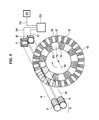
- FIG. 4 the device shown in FIG. 4 is a simple and effective solution to these difficulties.
- an emitter 6 which is constituted by two light cells 7 and 8 arranged so as to permanently emit light fluxes 9 and 10 directed parallel towards two receiving cells 11 and 12 which can be either photosensitive resistors or photoelectric cells or phototransistors.
- a rDoduiateur 14 constituted by a rigid disc rotating around an axis 14 is arranged so that its periphery intersects the light fluxes 9 and 10.
- This disc 13 is divided at its periphery into two rows 15 and 16 of strips 17, 18, 19, 20, alternately opaque and transparent. The means to be applied to produce a disc such as the disc 13 need not be described in detail.
- the transparent strips such as the strips 18 and 19 can be produced by openings or slots or notches made in a rigid disc, for example a metallic or plastic disc.
- the modulator 13 alternately has opaque and transparent bands, it could also, in another embodiment, have bands which are alternately opaque and reflective or transparent and reflective.
- the receiving cells 11 and 12 would be arranged so as to be impressed by the partial flows 9 and 10 when these flows are reflected by the reflecting strips. They would be arranged symmetrically to the transmitters 7 and 8 with respect to a plane perpendicular to that of the disc 13 this cutting this disc diametrically.
- the different bands 19 and 20 of the inner row 16 have a width which corresponds to the diameter of the partial flow of cylindrical shape 10 emitted by the cell 8.
- this partial flow passes entirely through the transparent bands 19 when the disc occupies such a position than that of fig 4, and consequently manages to impress the corresponding cell 12, experience shows that we are all the same, due to the inertia of the system, in a situation corresponding to that of FIG. 3a, that is to say that the wavy signal transmitted by the line 21 to the electronic circuit 22 is a signal having the shape of the curve 23 of this FIG. 3a.
- the partial flow 9 emitted by the cell 7 it partially crosses, when the disc 13 has the position of FIG. 4, one of the transparent bands 18, the width of the bands 17 and 18 of the row 15 being equal to 1/3 of the width of the bands 19 or 20 of the row 16.
- the partial position signal transmitted by the cell 11 in the line 24 will therefore have reduced to the scale of FIG. 3a a shape such as that of curve 25 of FIG. 3b.
- the partial flow 9 is still partially intercepted by two opaque bands 17 located on either side of the band 18 disposed on the path of the flow 9.
- f2 is obviously the angular speed of the disc 13 and t is time.
- the signals transmitted by lines 21 and 24 are weighted and added.
- the oscillating part of the signal transmitted by line 24 will be weighted by a coefficient k equal for example to 1: 10 and its constant part will be multiplied by (-1).
- k equal for example to 1: 10
- its constant part will be multiplied by (-1).
- the position signal resulting from the addition of the two partial signals, as it is produced in circuit 22, will have a shape such as that which is represented in the graph of FIG. 5.
- This signal is transmitted on line 25 to a receiver 26 which can be a display device or a transmission interface.
- Another important advantage of the treatment thus carried out is the following: it is known that during the use of cells such as the emitting cells 7 and 8 and receiving cells 11 and 12, the level of the mean amplitude U m of the signal captured varies. In fact, it gradually decreases due to cell aging. It is sufficient that the two cells are identical and are put into service at the same time so that the influence of these variations in aging is automatically eliminated.
- circuit 22 capable of weighting the oscillating part of the signal transmitted by the line 24 and of subtracting this thus weighted signal from the signal transmitted by the line 21. does not require a detailed description.
- Such a circuit can be produced by means of elements known in the field of electronics and it can be produced in the form of an integrated circuit.
- fig. 6 shows another arrangement, this time linear, of two rows 28 and 29 of alternately opaque and transparent bands, the opaque bands being designated by 30 and 31, while the transparent bands are designated by 32 and 33.
- the row of bands of row 29 is here also 1/3 of the width of the bands of row 28, although, if necessary, the addition of a harmonic of rank greater than 3 to the basic signal could also be considered.
- the diagram shown in fig. 6 could for example constitute the structure of a strip moving linearly in front of the two partial flows 9 and 10 of a light spot.
- the detector described could also, in another embodiment, use another type of flux, for example a flux particles or, if necessary, an electric current.
- the modulator could be arranged so as to act alternately to interrupt and initiate the passage of current in two branches separated from a network traversed by an electric current.
- other uses of flux can also be imagined.
Applications Claiming Priority (2)
| Application Number | Priority Date | Filing Date | Title |
|---|---|---|---|
| CH2007/85 | 1985-05-10 | ||
| CH200785 | 1985-05-10 |
Publications (1)
| Publication Number | Publication Date |
|---|---|
| EP0202194A1 true EP0202194A1 (de) | 1986-11-20 |
Family
ID=4223724
Family Applications (1)
| Application Number | Title | Priority Date | Filing Date |
|---|---|---|---|
| EP86810199A Withdrawn EP0202194A1 (de) | 1985-05-10 | 1986-05-02 | Detektor zum Messen der Verschiebung eines Objekts |
Country Status (1)
| Country | Link |
|---|---|
| EP (1) | EP0202194A1 (de) |
Cited By (5)
| Publication number | Priority date | Publication date | Assignee | Title |
|---|---|---|---|---|
| EP2177189A1 (de) | 2003-02-12 | 2010-04-21 | The Procter and Gamble Company | Saugfähiger Kern für einen saugfähigen Artikel |
| EP2314989A1 (de) * | 2009-10-22 | 2011-04-27 | Imperial Ltd. | Codierungsmuster mit passendem Öffnungsmuster, Verfahren zur Gestaltung des Codiermusters und optischer Bolzencodierer, in dem das Codiermuster und das Öffnungsmuster umgesetzt sind |
| CN102322887A (zh) * | 2011-06-28 | 2012-01-18 | 奇瑞汽车股份有限公司 | 方向盘转角传感器 |
| FR2990632A1 (fr) * | 2012-05-18 | 2013-11-22 | Vips France | Dispositif d'orientation d'articles dans un module de tri suivant une destination desiree |
| CN112994990A (zh) * | 2021-05-20 | 2021-06-18 | 蚂蚁金服(杭州)网络技术有限公司 | 一种环路检测方法、装置、电子设备与存储介质 |
-
1986
- 1986-05-02 EP EP86810199A patent/EP0202194A1/de not_active Withdrawn
Non-Patent Citations (1)
| Title |
|---|
| MEASUREMENT TECHNIQUES, vol. 27, no. 2, février 1984, pages 117-120, Plenum Publishing Corp., New York, US; V.P. SOLDATOV: "Elimination of the effect of differences in the signal shape on the accuracy of optoelectronic devices" * |
Cited By (7)
| Publication number | Priority date | Publication date | Assignee | Title |
|---|---|---|---|---|
| EP2177189A1 (de) | 2003-02-12 | 2010-04-21 | The Procter and Gamble Company | Saugfähiger Kern für einen saugfähigen Artikel |
| EP2177188A1 (de) | 2003-02-12 | 2010-04-21 | The Procter and Gamble Company | Saugfähiger Kern für einen saugfähigen Artikel |
| EP2314989A1 (de) * | 2009-10-22 | 2011-04-27 | Imperial Ltd. | Codierungsmuster mit passendem Öffnungsmuster, Verfahren zur Gestaltung des Codiermusters und optischer Bolzencodierer, in dem das Codiermuster und das Öffnungsmuster umgesetzt sind |
| WO2011048191A1 (en) * | 2009-10-22 | 2011-04-28 | Imperial Ltd. | An encoder pattern with matching aperture pattern, a method for designing said encoder pattern, and an optical shaft encoder in which the encoder pattern and aperture pattern are implemented |
| CN102322887A (zh) * | 2011-06-28 | 2012-01-18 | 奇瑞汽车股份有限公司 | 方向盘转角传感器 |
| FR2990632A1 (fr) * | 2012-05-18 | 2013-11-22 | Vips France | Dispositif d'orientation d'articles dans un module de tri suivant une destination desiree |
| CN112994990A (zh) * | 2021-05-20 | 2021-06-18 | 蚂蚁金服(杭州)网络技术有限公司 | 一种环路检测方法、装置、电子设备与存储介质 |
Similar Documents
| Publication | Publication Date | Title |
|---|---|---|
| EP0006482B1 (de) | Schaltung zur Erkennung der Maxima und Minima eines elektrischen Signals variabler Amplitude und niedriger Frequenz sowie Verwendung dieser Schaltung, um bei zwei sich zueinander bewegenden Objekten Ausmass und Richtung der Bewegung zu bestimmen | |
| EP1354220B1 (de) | Verfahren und vorrichtung zur hinderniserkennung und abstandmessung mittels infrarot | |
| CH643364A5 (fr) | Appareil de localisation de position d'un ou plusieurs objets. | |
| FR2459961A1 (fr) | Generateur de signaux de distance parcourue pour vehicules | |
| FR2596170A1 (fr) | Transducteur optique | |
| CH656731A5 (fr) | Appareil de localisation optique de position. | |
| FR2548355A1 (fr) | Systeme optique d'arpentage a laser | |
| EP0033282A1 (de) | Leitsystem für Raketen mittels eines modulierten optischen Strahles | |
| CH387978A (fr) | Procédé de comparaison d'intensités de lumière, comparateur pour la mise en oeuvre de ce procédé et application du procédé au réglage de l'admission de l'encre | |
| FR2506007A1 (fr) | Dispositif pour la mesure des coordonnees d'une sphere tournante et procede de fabrication d'une partie dudit dispositif | |
| EP0202194A1 (de) | Detektor zum Messen der Verschiebung eines Objekts | |
| EP0006441B1 (de) | Optische Anordnung für ein Positionsdetektionsapparat mit einem auf sich selbst reflektierten Gitter | |
| FR2670005A1 (fr) | Capteur de detection de la rotation d'un disque de compteur. | |
| EP0033279B1 (de) | Leitsystem für Raketen mittels eines optischen Strahles | |
| FR2591764A1 (fr) | Systeme optique de multiplexage et procede d'utilisation de ce systeme | |
| FR2497945A1 (fr) | Transducteur optique de deplacements | |
| EP0023902B1 (de) | Optische vorrichtung zur regelung oder steuerung von licht | |
| FR2548796A1 (fr) | Dispositif optique pour determiner la position et la forme de la surface d'un objet | |
| FR2542878A1 (fr) | Dispositif de balayage | |
| FR2530030A1 (fr) | Dispositif tachymetrique commande electroniquement | |
| FR2503857A1 (fr) | Dispositif pour guider un engin mobile | |
| FR2612647A1 (fr) | Dispositif de modulation pour un dispositif detecteur de rayonnement captant un champ d'image | |
| WO1991010880A2 (fr) | Dispositif de detection a distance d'une grandeur physique, fonctionnant en reflexion | |
| EP0485264B1 (de) | Kreiselsystem zum Vermessen der Neigung der Ebene der Achsen des Primaeren und des sekundären Rahmens in Bezug auf die Kreiselackse | |
| EP0524885B1 (de) | Interferometrischer Kreisel mit elektrooptischem Modulator |
Legal Events
| Date | Code | Title | Description |
|---|---|---|---|
| PUAI | Public reference made under article 153(3) epc to a published international application that has entered the european phase |
Free format text: ORIGINAL CODE: 0009012 |
|
| AK | Designated contracting states |
Kind code of ref document: A1 Designated state(s): CH DE FR GB IT LI |
|
| STAA | Information on the status of an ep patent application or granted ep patent |
Free format text: STATUS: THE APPLICATION IS DEEMED TO BE WITHDRAWN |
|
| 18D | Application deemed to be withdrawn |
Effective date: 19870521 |
|
| RIN1 | Information on inventor provided before grant (corrected) |
Inventor name: HEYRAUD, MARC |