EP0201863A1 - Fuel supply device for engines, particularly for model aircraft - Google Patents
Fuel supply device for engines, particularly for model aircraft Download PDFInfo
- Publication number
- EP0201863A1 EP0201863A1 EP86106254A EP86106254A EP0201863A1 EP 0201863 A1 EP0201863 A1 EP 0201863A1 EP 86106254 A EP86106254 A EP 86106254A EP 86106254 A EP86106254 A EP 86106254A EP 0201863 A1 EP0201863 A1 EP 0201863A1
- Authority
- EP
- European Patent Office
- Prior art keywords
- exhaust
- supply device
- fuel supply
- chamber
- fuel
- Prior art date
- Legal status (The legal status is an assumption and is not a legal conclusion. Google has not performed a legal analysis and makes no representation as to the accuracy of the status listed.)
- Granted
Links
Images

Classifications
-
- F—MECHANICAL ENGINEERING; LIGHTING; HEATING; WEAPONS; BLASTING
- F01—MACHINES OR ENGINES IN GENERAL; ENGINE PLANTS IN GENERAL; STEAM ENGINES
- F01N—GAS-FLOW SILENCERS OR EXHAUST APPARATUS FOR MACHINES OR ENGINES IN GENERAL; GAS-FLOW SILENCERS OR EXHAUST APPARATUS FOR INTERNAL COMBUSTION ENGINES
- F01N5/00—Exhaust or silencing apparatus combined or associated with devices profiting from exhaust energy
-
- F—MECHANICAL ENGINEERING; LIGHTING; HEATING; WEAPONS; BLASTING
- F02—COMBUSTION ENGINES; HOT-GAS OR COMBUSTION-PRODUCT ENGINE PLANTS
- F02B—INTERNAL-COMBUSTION PISTON ENGINES; COMBUSTION ENGINES IN GENERAL
- F02B75/00—Other engines
- F02B75/34—Ultra-small engines, e.g. for driving models
-
- F—MECHANICAL ENGINEERING; LIGHTING; HEATING; WEAPONS; BLASTING
- F02—COMBUSTION ENGINES; HOT-GAS OR COMBUSTION-PRODUCT ENGINE PLANTS
- F02M—SUPPLYING COMBUSTION ENGINES IN GENERAL WITH COMBUSTIBLE MIXTURES OR CONSTITUENTS THEREOF
- F02M37/00—Apparatus or systems for feeding liquid fuel from storage containers to carburettors or fuel-injection apparatus; Arrangements for purifying liquid fuel specially adapted for, or arranged on, internal-combustion engines
- F02M37/04—Feeding by means of driven pumps
- F02M37/12—Feeding by means of driven pumps fluid-driven, e.g. by compressed combustion-air
-
- Y—GENERAL TAGGING OF NEW TECHNOLOGICAL DEVELOPMENTS; GENERAL TAGGING OF CROSS-SECTIONAL TECHNOLOGIES SPANNING OVER SEVERAL SECTIONS OF THE IPC; TECHNICAL SUBJECTS COVERED BY FORMER USPC CROSS-REFERENCE ART COLLECTIONS [XRACs] AND DIGESTS
- Y02—TECHNOLOGIES OR APPLICATIONS FOR MITIGATION OR ADAPTATION AGAINST CLIMATE CHANGE
- Y02T—CLIMATE CHANGE MITIGATION TECHNOLOGIES RELATED TO TRANSPORTATION
- Y02T10/00—Road transport of goods or passengers
- Y02T10/10—Internal combustion engine [ICE] based vehicles
- Y02T10/12—Improving ICE efficiencies
Definitions
- the invention relates to a fuel supply device for model aircraft engines, consisting of a fuel tank closed to the atmosphere, which is connected via a fuel outlet line to the engine and a gas inlet line to an overpressure chamber in an exhaust designed as a silencer, the overpressure chamber on the inlet side is connected to the combustion gas outlet of the engine and has an exhaust gas outlet leading into the atmosphere.
- the object of the invention is to improve the known fuel supply device in such a way that the engine is supplied with sufficient fuel even in the event of a steep climb and / or strong acceleration.
- the overpressure of different heights which is required for a perfect fuel supply in the respective flight position, is ensured without complex control and regulation solely by the more or less strong throttling of the valve arrangement, which depends on the inclined position.
- the valve arrangement consists of at least one valve seat and at least one valve body movably mounted in a guide, the guide being arranged and designed in such a way that the force of gravity acting on the valve body in the direction of the valve seat has a component which is dependent on the inclined position of the exhaust can take effect.
- gravity is used for the degree of throttling of the valve in a very simple, purely mechanical manner.
- the valve arrangement preferably consists of several identical valves.
- the force with which the valve is throttled can be determined via the weight of the valve body. This can be done, for example, in such a way that at least one further movable valve body is held in each guide next to the valve body.
- a guide consisting of a longitudinally slotted tube is simple in construction.
- the exhaust consists of three axially arranged chambers, of which the two outer chambers are connected to one another via a pipe leading through the middle chamber and the second chamber in the flow direction of the exhaust gases with the middle chamber via the Valve arrangement is connected.
- the chambers are additionally connected to one another via a line leading into the atmosphere, wherein the line has inlets arranged at the deepest point of the chambers, the free cross section of which is significantly (a fraction) smaller than the free cross section of the other connections of the chambers.
- the exhaust consists of a circular cylindrical housing 1 and an insert dividing the housing 1 into three chambers 2, 3, 4 with walls 5, 6.
- the housing 1 is closed on one side by a molded cover 7 and on the other side by a cover 8 of the insert.
- the insert is held in the housing 1 on the housing cover 7 by means of a screw bolt 10 fastened to a central pin 9 of the insert.
- the chamber 2 is connected to the engine (not shown) by means of a combustion gas inlet 11 designed as a molded connection piece on the housing 1. From the chamber 4 is a combustion gas outlet 12 in the form of a hose connection, to which one is not shown set and leading to the tank line can be plugged, so that the prevailing pressure in the chamber 4 is transferred to the tank.
- a combustion gas inlet 11 designed as a molded connection piece on the housing 1.
- a combustion gas outlet 12 in the form of a hose connection, to which one is not shown set and leading to the tank line can be plugged, so that the prevailing pressure in the chamber 4 is transferred to the tank.
- the chambers 2 and 4 are connected to one another via three pipes 13, "1 " 4, 15 which are arranged symmetrically around the cylinder axis and held in the partition walls 5, 6.
- the combustion gases, which get into the chamber 2 via the nozzle 11, can thus continue to flow into the chamber 4 via the pipes 13 to 15.
- the chamber 4 is connected to the middle chamber 3 via three similar valves 16, 17, 18. From the middle chamber 3 there is a central pipeline 19 with inlet openings 20, 21 distributed around the circumference, which leads closed through the last chamber 4 into the atmosphere and forms the exhaust outlet.
- the three identical valves 16, 17, 18 are designed in the manner of check valves. They each consist of a valve seat 22 and a valve body 23 designed as a ball, which is loosely mounted in a guide 26 together with further balls 24, 25.
- the guide 26 is formed by a tube which has a plurality of longitudinal slots 28.
- valve body 23 sits on the associated valve seat 22 and closes the valve with a force that is dependent on the inclined position of the exhaust.
- This force is increased by the additional, movable bodies 24, 25.
- an overpressure corresponding to this force builds up, so that a greater overpressure is created in the tank than during horizontal flight. This greater overpressure ensures that the engine is supplied with a sufficient amount of fuel even when climbing.
- valve body 23 Due to the possible mobility of the valve body 23 in the direction of movement of the model aircraft, an inertia moment also acts on the valve body 23 during the positive and negative acceleration.
- the valve arrangement is therefore arranged such that the valve body 23 throttles to a greater or lesser extent when the acceleration is positive, so that a sufficient positive pressure is also available in this phase, which is critical for the fuel supply, in order to supply the engine with sufficient fuel.
- valves acting as check valves 16, 17, 18 prevent the engine from drawing in return air. This results in smoother engine running.
- Oil in the exhaust gases which is deposited on the walls of the housing and collects in the lower region of the housing, is discharged via line 29 with the pressure prevailing in the individual chambers 2, 3, 4. In this way it is prevented that too much oil collects in the housing 1 and in the cold state the mobility of the valve body 23 and thus its function of the independent pressure control is impaired.
Abstract
Description
Die Erfindung bezieht sich auf eine Brennstoffversorgungseinrichtung für Modellflugzeugmotoren, bestehend aus einem gegenüber der Atmosphäre verschlossenen Brennstofftank, der über eine Brennstoff-Auslaßleitung mit dem Motor und eine Gas-Einlaßleitung mit einer Überdruckkammer in einem als Schalldämpfer ausgebildeten Auspuff verbunden ist, wobei die Überdruckkammer einlaßseitig mit dem Verbrennungsgas-Auslaß des Motors verbunden ist und einen in die Atmosphäre führenden Auspuffgas-Auslaß aufweist.The invention relates to a fuel supply device for model aircraft engines, consisting of a fuel tank closed to the atmosphere, which is connected via a fuel outlet line to the engine and a gas inlet line to an overpressure chamber in an exhaust designed as a silencer, the overpressure chamber on the inlet side is connected to the combustion gas outlet of the engine and has an exhaust gas outlet leading into the atmosphere.
Eine solche Brennstoffversorgungseinrichtung ist bekannt (DE-Z "Modell" 2/85, Seite 93).Such a fuel supply device is known (DE-Z "Modell" 2/85, page 93).
Während unter normalen Flugbedingungen (Horizontalflug und sanfter Steigeflug) der in der Überdruckkammer herrsehende Druck ausreicht, den vom Motor benötigten Brennstoff aus dem Tank in die Brennstoff-Auslaßleitung zu drücken, reicht dieser Druck bei starkem Steigflug dafür nicht mehr aus. Entsprechende Verhältnisse können sich ja nach Lage des Tanks und des Einlasses der Brennstoff-Auslaßleitung bei einer starken Beschleunigung des Modellflugzeuges oder eines anderen, motorgetriebenen Fahrzeuges ergeben. Wenn der im Tank erzeugte Druck für die Brennstoffversorgung nicht mehr ausreicht, kommt es zum Aussetzen des Motors. Darüber hinaus haben Untersuchungen gezeigt, daß der Motor ungleichmäßig läuft, wenn er die Möglichkeit hat, aus dem Auspuff Rückluft zu holen.While under normal flight conditions (horizontal flight and gentle climb) the pressure in the pressure chamber is sufficient to push the fuel required by the engine from the tank into the fuel outlet line, this pressure is no longer sufficient for a steep climb. Corresponding conditions can arise depending on the position of the tank and the inlet of the fuel outlet line when the model airplane or another motor-driven vehicle accelerates strongly. When the pressure generated in the tank is no longer sufficient for the fuel supply, comes it to stop the engine. In addition, studies have shown that the engine runs unevenly if it has the ability to return air from the exhaust.
Der Erfindung liegt die Aufgabe zugrunde, die bekannte Brennstoffversorgungsvorrsichtung derart zu verbessern, daß der Motor auch bei starkem Steigflug und/oder starker Beschleunigung mit ausreichendem Brennstoff versorgt wird.The object of the invention is to improve the known fuel supply device in such a way that the engine is supplied with sufficient fuel even in the event of a steep climb and / or strong acceleration.
Bei der erfindungsgemäßen Brennstoffversorgungseinrichtung wird ohne aufwendige Steuerung und Regelung der bei der jeweiligen Fluglage für eine einwandfreie Brennstoffversorgung unterschiedlich hohe Überdruck allein durch die von der Schräglage abhängige mehr oder weniger starke Drosselung der Ventilanordnung gewährleistet.In the fuel supply device according to the invention, the overpressure of different heights, which is required for a perfect fuel supply in the respective flight position, is ensured without complex control and regulation solely by the more or less strong throttling of the valve arrangement, which depends on the inclined position.
Der gleiche Effekt wird auch bei positiver und negativer Beschleunigung eines motorgetriebenen Fahrzeuges erreicht, weil die Trägheitskräfte das Ventil steuern.The same effect is achieved with positive and negative acceleration of a motor-driven vehicle because the inertial forces control the valve.
Nach einer Ausgestaltung der Erfindung besteht die Ventilanordnung aus mindestens einemVentilsitz und mindestens einem in einer Führung beweglich gelagerten Vetilkörper, wobei die Führung derart angeordnet und ausgebildet ist, daß die auf den Ventilkörper in Richtung des Ventilsitzes einwirkende Schwerkraft mit einer von der Schräglage des Auspuffes abhängigen Komponenten wirksam werden kann. Bei dieser Ausgestaltung der Erfindung wird auf denkbar einfache, rein mechanische Art und Weise die Schwerkraft für den Drosselungsgrad des Ventils ausgenutzt.According to one embodiment of the invention, the valve arrangement consists of at least one valve seat and at least one valve body movably mounted in a guide, the guide being arranged and designed in such a way that the force of gravity acting on the valve body in the direction of the valve seat has a component which is dependent on the inclined position of the exhaust can take effect. In this embodiment of the invention, gravity is used for the degree of throttling of the valve in a very simple, purely mechanical manner.
Die Ventilanordnung besteht vorzugsweise aus mehreren gleichartigen Ventilen. Über das Gewicht der Ventilkörper kann die Kraft bestimmt werden, mit der die Drosselung des Ventils erfolgen soll. Dies kann beispielsweise in der Form geschehen, daß in jeder Führung neben dem Ventilkörper mindestens ein weiterer beweglicher Ventilkörper gehalten ist. In der Konstruktion einfach ist eine Führung, die aus einem längssgeschlitzten Rohr besteht.The valve arrangement preferably consists of several identical valves. The force with which the valve is throttled can be determined via the weight of the valve body. This can be done, for example, in such a way that at least one further movable valve body is held in each guide next to the valve body. A guide consisting of a longitudinally slotted tube is simple in construction.
Es hat sich insbesondere bei mehreren Ventilen als zweckmäßig erwiesen, wenn die Führung des Ventilkörpers in einer weiteren Kammer im Auspuff angeordnet ist, von der der in die Atmosphäre führende Auspuffgas-Auslaß ausgeht.It has proven to be expedient in particular in the case of a plurality of valves if the guide of the valve body is arranged in a further chamber in the exhaust pipe, from which the exhaust gas outlet leading into the atmosphere originates.
Bei einer bereits in der Praxis bewährten Brennstoffversorgungseinrichtung besteht der Auspuff aus drei axial hintereinander angeordneten Kammern, von denen die beiden äußeren Kammern über eine geschlossen durch die mittlere Kammer führende Rohrleitung miteinander verbunden sind und die in Strömungsrichtung der Auspuffgase zweite Kammer mit der mittleren Kammer über die Ventilanordnung verbunden ist.In a fuel supply device that has already been tried and tested in practice, the exhaust consists of three axially arranged chambers, of which the two outer chambers are connected to one another via a pipe leading through the middle chamber and the second chamber in the flow direction of the exhaust gases with the middle chamber via the Valve arrangement is connected.
Da der Brennstoff in der Regel öl enthält, das bei kaltem Auspuff die Beweglichkeit der Ventilkörper behindern und damit die Funktion der Ventilanordnung beeinträchtigen könnte, ist nach einer weiteren Ausgestaltung vorgesehen, daß die Kammern zusätzlich über eine in die Atmosphäre führende Leitung miteinander verbunden sind, wobei die Leitung an der tiefsten Stelle der Kammern angeordnete Einlässe aufweist, deren freier Querschnitt wesentlich (ein Bruchteil) kleiner als der freie Querschnitt der übrigen Verbindungen der Kammern ist.Since the fuel generally contains oil, which could hinder the mobility of the valve body when the exhaust is cold and could thus impair the function of the valve arrangement, it is provided according to a further embodiment that the chambers are additionally connected to one another via a line leading into the atmosphere, wherein the line has inlets arranged at the deepest point of the chambers, the free cross section of which is significantly (a fraction) smaller than the free cross section of the other connections of the chambers.
Im folaenden wird die Erfindung anhand einer ein Ausführungsbeispiel darstellenden Zeichnung näher erläutert. Im einzelnen zeigen
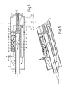
- Fig. 1 einen Auspuff in Seitenansicht, teilweise bei weggebrochener Gehäuse,
- Fig. 2 den Auspuff gem. Fig. 1 in Stirnansicht von der Seite des Auspuffgas-Auslasses,
- Fig. 3 den Auspuff gem. Fig. 1 im Querschnitt nach der Linie I - I der Fig. 1,
- Fig. 4 den Auspuff gem. Fig. 1 im Axialschnitt , nach der Linie II - II der Fig. 2 und
- Fig. 5 einen Teil des Auspuffes gem. Fig. 1 beim Steigflug im Axialschnitt nach der Linie II - II der Fig. 2.
- 1 is an exhaust in side view, partially with the housing broken away,
- Fig. 2 shows the exhaust. 1 is an end view from the side of the exhaust gas outlet,
- Fig. 3 shows the exhaust. 1 in cross section along the line I - I of FIG. 1,
- Fig. 4 shows the exhaust. Fig. 1 in axial section, along the line II - II of Fig. 2 and
- Fig. 5 shows a part of the exhaust. 1 when climbing in axial section along the line II - II of FIG. 2nd
Der Auspuff besteht aus einen kreiszylindrischen Gehäuse 1 und einem das Gehäuse 1 in drei Kammern 2, 3, 4 mit Wänden 5, 6 unterteilenden Einsatz. Das Gehäuse 1 ist auf der einen Seite durch einen angeformten Deckel 7 und auf der anderen Seite durch einen Deckel 8 des Einsatzes verschlossen. Der Einsatz wird im Gehäuse 1 mittels eines an einem zentralen Zapfen 9 des Einsatzes befestig- ten Schraubenbolzens 10 am Gehäusedeckel 7 gehalten.The exhaust consists of a circular
Die Kammer 2 ist mittels eines als angeformter Stutzen am Gehäuse 1 ausgebildeten Verbrennungsgas-Einlasses 11 mit dem nicht dargestellten Motor verbunden. Von der Kammer 4 geht ein Verbrennungsgas-Auslaß 12 in Form eines Schlauchanschlusses aus, auf den eine nicht dargestellte und zum Tank führende Leitung aufsteckbar ist, so daß der in der Kammer 4 herrschende Druck in den Tank übertragen wird.The
Die Kammern 2 und 4 sind über drei symmetrisch um die Zylinderachse verteilt angeordnete und in den Trennwänden 5, 6 gehaltene Rohrleitungen 13, "1"4, 15 miteinander verbunden. Die Verbrennungsgase, die über den Stutzen 11 in die Kammer 2 gelangen, können also über die Rohrleitungen 13 bis 15 in die Kammer 4 weiterströmen. Die Kammer 4 ist über drei gleichartige Ventile 16, 17, 18 mit der mittleren Kammer 3 verbunden. Von der mittleren Kammer 3 geht eine zentrale Rohrleitung 19 mit am Umfang verteilten Einlaßöffnungen 20, 21 aus, die geschlossen durch die letzte Kammer 4 in die Atmosphäre führt und den Auspuff-Auslaß bildet.The
Die drei gleichartigen Ventile 16,17,18 sind nach Art - von Rückschlagventilen ausgebildet. Sie bestehen jeweils aus einem Ventilsitz 22 und einem als Kugel ausgebildeten Ventilkörper 23, der zusammen mit weiteren Kugeln 24, 25 in einer Führung 26 lose gelagert ist. Die Führung 26 wird von einem Rohr gebildet, das mehrere Längsschlitze 28 aufweist.The three
Am Boden des Gehäuses 7 ist eine in den Trennwänden 5, 6 und dem Deckel 8 gehaltene Leitung 29 angeordnet, die im Bereich der Trennwände 5, 6 und des Deckels 8 zu den einzelnen Kammern 2, 3, 4 hin offene Einlässe 30, 31, 32 aufweist und mit ihrem Auslaß 33 in die Atmosphäre führt.At the bottom of the housing 7 there is a
Die Funktion der erfirdungsgemäßen Brennstoffversorgung ist folgende:
- Die vom Motor erzeugten Verbrennungsgase gelangen über den Verbrennungsgas-
Auslaß 11 in dieKammer 2, von der sie über dieLeitungen 13 bis 15 in dieKammer 4 gelangen. In dieserKammer 4 baut sich ein gewisser Überdruck auf. Dieser Druck wird über den Verbrennungsgas-Auslaß 12 in den Tank übertragen, so daß der Brennstoff aus dem Tank mit Druck dem Motor zugeführt wird. Wie groß der Druck ist, hängt von der durch die Lage des Flugzeuges bestimmten Lage des Auspuffes ab. Solange das Flugzeug sich im Horizontalflug befindet, kann der Druck ohne größeren Widerstand über dieVentile 16 bis 18 in diemittlere Kammer 3 und von dermittleren Kammer 3 über dieLeitung 19 in die Atmosphäre strömen. Es kann u.U. erforderlich sein, dieVentilkörper 23 mittels einer Feder vorzubelasten, damit sich in derKammer 4 auch beim Horizontalflug ein ausreichender Überdruck bildet. Es ist aber auch möglich, durch eine natürliche, konstante Drosselung der einzelnen Auslässe für einen solchen Überdruck zu sorgen.
- The combustion gases generated by the engine pass through the
combustion gas outlet 11 into thechamber 2, from which they reach thechamber 4 via thelines 13 to 15. A certain excess pressure builds up in thischamber 4. This pressure is transferred into the tank via thecombustion gas outlet 12 so that the fuel from the tank is supplied to the engine under pressure. How big the pressure is depends on the position of the exhaust determined by the position of the aircraft. As long as the aircraft is in horizontal flight, the pressure can flow through thevalves 16 to 18 into themiddle chamber 3 and from themiddle chamber 3 via theline 19 into the atmosphere without greater resistance. It may be necessary to preload thevalve body 23 by means of a spring so that a sufficient overpressure forms in thechamber 4 even during horizontal flight. However, it is also possible to provide such overpressure by means of a natural, constant throttling of the individual outlets.
Sobald sich das Flugzeug in den Steigflug begibt, setzt sich der Ventilkörper 23 auf den zugehörigen Ventilsitz 22 und verschließt das Ventil mit einer von der Schräglage des Auspuffes abhängigen Kraft. Durch die zusätzlichen, beweglichen Rörper 24,25 wird diese Kraft verstärkt. In der Kammer 3 baut sich ein dieser Kraft entsprechender Überdruck auf, so daß im Tank ein größerer Überdruck als beim Horizontalflug entsteht. Dieser größere Überdruck sorgt dafür, daß auch beim Steigflug der Motor mit einer ausreichenden Brennstoffmenge versorgt wird.As soon as the aircraft begins to climb, the
Aufgrund der in Bewegungsrichtung des Modellflugzeuges möglichen Beweglichkeit der Ventilkörper 23 wirkt auf die Ventilkörper 23 auch ein Trägheitsmoment bei der positiven und negativen Beschleunigung ein. Die Ventilanordnung ist deshalb so angeordnet, daß bei einer positiven Beschleunigung der Ventilkörper 23 mehr oder weniger stark drosselt, so daß auch in dieser für die Brennstoffversorgung kritischen Phase ein ausreichender Überdruck zur Verfügung steht, um den Motor mit ausreichend Brennstoff zu versorgen.Due to the possible mobility of the
Es hat sich gezeigt, daß die als Rückschlagventile 16,17,18 wirkenden Ventile verhindern, daß der Motor Rückluft holt. Dadurch wird ein ruhigerer Motorlauf erreicht.It has been shown that the valves acting as
Öl in den Auspuffgasen, das sich an den Wänden des Gehäuses niederschlägt und in dem unteren Bereich des Gehäuses sich sammelt, wird über die Leitung 29 mit dem in den einzelnen Kammern 2,3,4 herrschenden Druck ausgefördert. Es wird auf diese Art und Weise verhindert, daß sich zu viel Öl in dem Gehäuse 1 sammelt und im kalten Zustand die Beweglichkeit der Ventilkörper 23 und damit ihre Funktion der selbständigen Druckregelung beeinträchtigt.Oil in the exhaust gases, which is deposited on the walls of the housing and collects in the lower region of the housing, is discharged via
Claims (8)
dadurch gekennzeichnet ,
daß die Ventilanordnung aus mehreren gleichartigen Ventilen (16,17,18) besteht.3. Fuel supply device according to claim 1 or 2,
characterized ,
that the valve arrangement consists of several similar valves (16, 17, 18).
dadurch gekennzeichnet ,
daß in der Führung (26) des Ventilkörpers (23) neben dem Ventilkörper (23) mindestens ein weiterer, beweglicher Körper (24,25) gehalten ist.4. Fuel supply device according to one of claims 1 to 3,
characterized ,
that at least one further movable body (24, 25) is held in the guide (26) of the valve body (23) next to the valve body (23).
dadurch gekennzeichnet,
daß die Führung (26) aus einem längsgeschlitzten Rohr besteht.5. Fuel supply device according to one of claims 1 to 4,
characterized,
that the guide (26) consists of a longitudinally slotted tube.
dadurch gekennzeichnet ,
daß die Führung (26) des Ventilkörpers (23) in einer weiteren Kammer (3) im Auspuff angeordnet ist, von der der in die Atmosphäre führende Auspuffgas-Auslaß (19) ausgeht.6. Fuel supply device according to one of claims 1 to 5,
characterized ,
that the guide (26) of the valve body (23) is arranged in a further chamber (3) in the exhaust, from which the exhaust gas outlet (19) leading into the atmosphere originates.
dadurch gekennzeichnet ,
daß der Auspuff drei axial hintereinander angeordnete Kammern (2,3,4) aufweist, von denen die beiden äußeren Kammern (2,4) über mindestens eine geschlossen durch die mittlere Kammer (3) führende Rohrleitung (13,14,15) miteinander verbunden sind und die in Strömungsrichtung der Auspuffgase zweite Kammer (4) mit der mittleren Kammer (3) über die Ventilanordnung (16,17,18) verbunden ist.7. Fuel supply device according to one of claims 1 to 6,
characterized ,
that the exhaust has three axially successive chambers (2, 3, 4), of which the two outer chambers (2, 4) are connected to one another by at least one pipe (13, 14, 15) leading through the middle chamber (3) are in the direction of flow the exhaust gases of the second chamber (4) is connected to the middle chamber (3) via the valve arrangement (16, 17, 18).
dadurch gekennzeichnet ,
daß die Kammern (2,3,4) zusätzlich über eine in die Atmosphäre führende Leitung (29) miteinander verbunden sind, wobei die Leitung (29) an der tiefsten Stelle der Kammern (2,3,4) Einlässe (30,31,32) aufweist, deren freier Querschnitt wesentlich (ein Bruchteil) kleiner als der freie Querschnitt der übrigen Verbindungen (13-18) ist.8. Fuel supply device according to one of claims 1 to 7,
characterized ,
that the chambers (2, 3, 4) are additionally connected to one another via a line (29) leading into the atmosphere, the line (29) at the lowest point of the chambers (2, 3, 4) inlets (30, 31, 32), the free cross section of which is significantly (a fraction) smaller than the free cross section of the other connections (13-18).
Priority Applications (1)
| Application Number | Priority Date | Filing Date | Title |
|---|---|---|---|
| AT86106254T ATE44401T1 (en) | 1985-05-11 | 1986-05-07 | FUEL SUPPLY DEVICE FOR ENGINES, ESPECIALLY OF MODEL AIRCRAFT. |
Applications Claiming Priority (2)
| Application Number | Priority Date | Filing Date | Title |
|---|---|---|---|
| DE3517120 | 1985-05-11 | ||
| DE3517120A DE3517120C1 (en) | 1985-05-11 | 1985-05-11 | Fuel supply device for engines, in particular model aircraft |
Publications (2)
| Publication Number | Publication Date |
|---|---|
| EP0201863A1 true EP0201863A1 (en) | 1986-11-20 |
| EP0201863B1 EP0201863B1 (en) | 1989-07-05 |
Family
ID=6270558
Family Applications (1)
| Application Number | Title | Priority Date | Filing Date |
|---|---|---|---|
| EP86106254A Expired EP0201863B1 (en) | 1985-05-11 | 1986-05-07 | Fuel supply device for engines, particularly for model aircraft |
Country Status (5)
| Country | Link |
|---|---|
| US (1) | US4731992A (en) |
| EP (1) | EP0201863B1 (en) |
| JP (1) | JPS6217360A (en) |
| AT (1) | ATE44401T1 (en) |
| DE (2) | DE3517120C1 (en) |
Families Citing this family (3)
| Publication number | Priority date | Publication date | Assignee | Title |
|---|---|---|---|---|
| US5706776A (en) * | 1997-02-20 | 1998-01-13 | Luehring; Elmer L. | Fuel tank backfilling system for vehicles |
| DE202005011448U1 (en) * | 2005-07-18 | 2006-11-23 | Kess, Roland | Silencer outlet part for a motorcycle silencer |
| WO2009014780A2 (en) * | 2007-04-26 | 2009-01-29 | Lord Corporation | Noise controlled turbine engine with aircraft engine adaptive noise control tubes |
Citations (6)
| Publication number | Priority date | Publication date | Assignee | Title |
|---|---|---|---|---|
| FR495587A (en) * | 1917-09-19 | 1919-10-11 | Francois Georges Champion | Safety device for aircraft fuel tanks |
| CH100070A (en) * | 1921-11-07 | 1923-07-02 | Schworetzky Gustav | Gas syringe with fixed spray nozzle and ball valves, which allow spraying upwards and downwards without letting compressed gas escape unused. |
| US2059325A (en) * | 1930-06-20 | 1936-11-03 | Carter Carburetor Corp | Fuel supply system for internal combustion engines |
| US2372700A (en) * | 1941-07-29 | 1945-04-03 | Stewart Warner Corp | Fuel feeding system |
| GB832936A (en) * | 1956-12-06 | 1960-04-21 | Ronald Bryson Stewart | Outlet selector valve for tiltable and invertible tank |
| DE2235913A1 (en) * | 1971-10-20 | 1973-04-26 | Yamada Shoji | DEVICE FOR REGULATING THE SUPPLY OF FUEL TO A MODEL ENGINE |
Family Cites Families (7)
| Publication number | Priority date | Publication date | Assignee | Title |
|---|---|---|---|---|
| US1363001A (en) * | 1918-05-10 | 1920-12-21 | Lockhart George | Submarine |
| US2071116A (en) * | 1935-04-10 | 1937-02-16 | Int Harvester Co | Charge forming device for internal combustion engines |
| US2175463A (en) * | 1938-01-03 | 1939-10-10 | Thomas L Cummings | Internal combustion motor |
| US2919540A (en) * | 1957-02-25 | 1960-01-05 | Gen Motors Corp | Mechanism for utilizing waste heat |
| US2966036A (en) * | 1959-02-19 | 1960-12-27 | Stowens Daniel | Method and apparatus for processing products of combustion |
| US3500635A (en) * | 1968-04-11 | 1970-03-17 | John H Roper | Gas pressure producing apparatus |
| US4643272A (en) * | 1985-05-30 | 1987-02-17 | Gaffrig James W | Marine muffler for water-cooled internal combustion engines |
-
1985
- 1985-05-11 DE DE3517120A patent/DE3517120C1/en not_active Expired
-
1986
- 1986-05-06 US US06/860,145 patent/US4731992A/en not_active Expired - Fee Related
- 1986-05-07 EP EP86106254A patent/EP0201863B1/en not_active Expired
- 1986-05-07 AT AT86106254T patent/ATE44401T1/en not_active IP Right Cessation
- 1986-05-07 DE DE8686106254T patent/DE3664225D1/en not_active Expired
- 1986-05-09 JP JP61104995A patent/JPS6217360A/en active Pending
Patent Citations (6)
| Publication number | Priority date | Publication date | Assignee | Title |
|---|---|---|---|---|
| FR495587A (en) * | 1917-09-19 | 1919-10-11 | Francois Georges Champion | Safety device for aircraft fuel tanks |
| CH100070A (en) * | 1921-11-07 | 1923-07-02 | Schworetzky Gustav | Gas syringe with fixed spray nozzle and ball valves, which allow spraying upwards and downwards without letting compressed gas escape unused. |
| US2059325A (en) * | 1930-06-20 | 1936-11-03 | Carter Carburetor Corp | Fuel supply system for internal combustion engines |
| US2372700A (en) * | 1941-07-29 | 1945-04-03 | Stewart Warner Corp | Fuel feeding system |
| GB832936A (en) * | 1956-12-06 | 1960-04-21 | Ronald Bryson Stewart | Outlet selector valve for tiltable and invertible tank |
| DE2235913A1 (en) * | 1971-10-20 | 1973-04-26 | Yamada Shoji | DEVICE FOR REGULATING THE SUPPLY OF FUEL TO A MODEL ENGINE |
Also Published As
| Publication number | Publication date |
|---|---|
| US4731992A (en) | 1988-03-22 |
| JPS6217360A (en) | 1987-01-26 |
| ATE44401T1 (en) | 1989-07-15 |
| DE3664225D1 (en) | 1989-08-10 |
| DE3517120C1 (en) | 1986-11-27 |
| EP0201863B1 (en) | 1989-07-05 |
Similar Documents
| Publication | Publication Date | Title |
|---|---|---|
| DE3000781C2 (en) | Device for controlling the actuation pressure for the actuator of a bypass valve in a bypass line of the turbine of an exhaust gas turbocharger | |
| DE4229110C1 (en) | Device for the temporary storage and metered feeding of volatile fuel components located in the free space of a tank system into the intake pipe of an internal combustion engine | |
| DE1576593B1 (en) | Diaphragm carburetor for internal combustion engines | |
| DE2736317C2 (en) | Fuel system for engines with compression ignition | |
| DE2311407A1 (en) | DEVICE FOR REGULATING THE EXHAUST GAS RECIRCULATION IN COMBUSTION ENGINE | |
| DE2855445C2 (en) | Two-stroke internal combustion engine | |
| DE3243996C1 (en) | Method for applying a polymer coating in the intake system of an internal combustion engine | |
| DE4229408C1 (en) | Air intake device for IC engine with crankcase ventilation - has flow divider chamber, and ventilation opens into it via tube end section, which is connected to pressure control valve | |
| EP1087109A2 (en) | Valve drive for internal combustion engine | |
| EP0201863A1 (en) | Fuel supply device for engines, particularly for model aircraft | |
| DE3039613C2 (en) | System for regulating the idling speed of gasoline engines | |
| DE2940235C2 (en) | Device for automatic replenishment of the lubricating oil in the crankcase of an internal combustion engine | |
| DE3635310A1 (en) | METHOD AND DEVICE FOR DELIVERING FUEL TO AN ENGINE | |
| DE2758167C2 (en) | Device for recirculating exhaust gases on carburetors of internal combustion engines | |
| DE2135206A1 (en) | Exhaust system for internal combustion engine | |
| DE2631257B2 (en) | Actuator for an air flap arranged in the charge air line of a diesel engine | |
| DD243967A5 (en) | CONTROL VALVE FOR DOUBLE-ACTING PNEUMATIC WORKING CYLINDERS | |
| WO2008095214A1 (en) | Apparatus for exhaust-gas recirculation for an internal combustion engine | |
| DE3632035A1 (en) | Actuating device for the power control element of an internal combustion engine | |
| DE2516582A1 (en) | ROTARY PISTON COMPRESSOR | |
| DE3621641A1 (en) | DEVICE FOR CONTROLLING THE CHARGE PRESSURE OF AN EXHAUST TURBOCHARGER | |
| DE3043527C2 (en) | ||
| DE165360C (en) | ||
| DE20320046U1 (en) | Valve arrangement for guiding a liquid against a gas pressure gradient | |
| DE1526745B1 (en) | Carburetor with fuel chamber for internal combustion engines |
Legal Events
| Date | Code | Title | Description |
|---|---|---|---|
| PUAI | Public reference made under article 153(3) epc to a published international application that has entered the european phase |
Free format text: ORIGINAL CODE: 0009012 |
|
| 17P | Request for examination filed |
Effective date: 19860919 |
|
| AK | Designated contracting states |
Kind code of ref document: A1 Designated state(s): AT BE CH DE FR GB IT LI LU NL SE |
|
| 17Q | First examination report despatched |
Effective date: 19870508 |
|
| GRAA | (expected) grant |
Free format text: ORIGINAL CODE: 0009210 |
|
| AK | Designated contracting states |
Kind code of ref document: B1 Designated state(s): AT BE CH DE FR GB IT LI LU NL SE |
|
| PG25 | Lapsed in a contracting state [announced via postgrant information from national office to epo] |
Ref country code: IT Free format text: LAPSE BECAUSE OF FAILURE TO SUBMIT A TRANSLATION OF THE DESCRIPTION OR TO PAY THE FEE WITHIN THE PRE;WARNING: LAPSES OF ITALIAN PATENTS WITH EFFECTIVE DATE BEFORE 2007 MAY HAVE OCCURRED AT ANY TIME BEFORE 2007. THE CORRECT EFFECTIVE DATE MAY BE DIFFERENT FROM THE ONE RECORDED.SCRIBED TIME-LIMIT Effective date: 19890705 Ref country code: FR Free format text: THE PATENT HAS BEEN ANNULLED BY A DECISION OF A NATIONAL AUTHORITY Effective date: 19890705 Ref country code: NL Effective date: 19890705 Ref country code: BE Effective date: 19890705 Ref country code: GB Effective date: 19890705 |
|
| REF | Corresponds to: |
Ref document number: 44401 Country of ref document: AT Date of ref document: 19890715 Kind code of ref document: T |
|
| REF | Corresponds to: |
Ref document number: 3664225 Country of ref document: DE Date of ref document: 19890810 |
|
| EN | Fr: translation not filed | ||
| NLV1 | Nl: lapsed or annulled due to failure to fulfill the requirements of art. 29p and 29m of the patents act | ||
| GBV | Gb: ep patent (uk) treated as always having been void in accordance with gb section 77(7)/1977 [no translation filed] | ||
| PG25 | Lapsed in a contracting state [announced via postgrant information from national office to epo] |
Ref country code: SE Effective date: 19900201 |
|
| PLBE | No opposition filed within time limit |
Free format text: ORIGINAL CODE: 0009261 |
|
| STAA | Information on the status of an ep patent application or granted ep patent |
Free format text: STATUS: NO OPPOSITION FILED WITHIN TIME LIMIT |
|
| PG25 | Lapsed in a contracting state [announced via postgrant information from national office to epo] |
Ref country code: AT Effective date: 19900507 |
|
| PG25 | Lapsed in a contracting state [announced via postgrant information from national office to epo] |
Ref country code: LI Effective date: 19900531 Ref country code: CH Effective date: 19900531 Ref country code: LU Free format text: LAPSE BECAUSE OF NON-PAYMENT OF DUE FEES Effective date: 19900531 |
|
| 26N | No opposition filed | ||
| REG | Reference to a national code |
Ref country code: CH Ref legal event code: PL |
|
| PG25 | Lapsed in a contracting state [announced via postgrant information from national office to epo] |
Ref country code: DE Effective date: 19910201 |