EP0201814A2 - Sich selbst orientierende Rohrsonde - Google Patents
Sich selbst orientierende Rohrsonde Download PDFInfo
- Publication number
- EP0201814A2 EP0201814A2 EP86106020A EP86106020A EP0201814A2 EP 0201814 A2 EP0201814 A2 EP 0201814A2 EP 86106020 A EP86106020 A EP 86106020A EP 86106020 A EP86106020 A EP 86106020A EP 0201814 A2 EP0201814 A2 EP 0201814A2
- Authority
- EP
- European Patent Office
- Prior art keywords
- conduit
- probe
- carrier
- curved
- axis
- Prior art date
- Legal status (The legal status is an assumption and is not a legal conclusion. Google has not performed a legal analysis and makes no representation as to the accuracy of the status listed.)
- Granted
Links
- 239000000523 sample Substances 0.000 title claims abstract description 37
- 238000005452 bending Methods 0.000 claims description 9
- 239000004020 conductor Substances 0.000 claims description 2
- 238000005260 corrosion Methods 0.000 description 5
- 230000007797 corrosion Effects 0.000 description 5
- 230000015556 catabolic process Effects 0.000 description 3
- 238000006731 degradation reaction Methods 0.000 description 3
- 239000004677 Nylon Substances 0.000 description 2
- 230000008901 benefit Effects 0.000 description 2
- 239000002826 coolant Substances 0.000 description 2
- 230000008878 coupling Effects 0.000 description 2
- 238000010168 coupling process Methods 0.000 description 2
- 238000005859 coupling reaction Methods 0.000 description 2
- 238000005336 cracking Methods 0.000 description 2
- 239000012530 fluid Substances 0.000 description 2
- 230000003993 interaction Effects 0.000 description 2
- 238000000034 method Methods 0.000 description 2
- 229920001778 nylon Polymers 0.000 description 2
- 239000012858 resilient material Substances 0.000 description 2
- 239000004698 Polyethylene Substances 0.000 description 1
- 230000009286 beneficial effect Effects 0.000 description 1
- 150000001875 compounds Chemical class 0.000 description 1
- 239000012141 concentrate Substances 0.000 description 1
- 238000001514 detection method Methods 0.000 description 1
- 230000000694 effects Effects 0.000 description 1
- 230000003628 erosive effect Effects 0.000 description 1
- 238000010438 heat treatment Methods 0.000 description 1
- 238000003780 insertion Methods 0.000 description 1
- 230000037431 insertion Effects 0.000 description 1
- 238000004519 manufacturing process Methods 0.000 description 1
- 239000000463 material Substances 0.000 description 1
- 238000005259 measurement Methods 0.000 description 1
- -1 polyethylene Polymers 0.000 description 1
- 229920000573 polyethylene Polymers 0.000 description 1
- 238000010248 power generation Methods 0.000 description 1
- 230000005855 radiation Effects 0.000 description 1
- 230000003252 repetitive effect Effects 0.000 description 1
- 239000000126 substance Substances 0.000 description 1
- 238000011179 visual inspection Methods 0.000 description 1
Images

Classifications
-
- G—PHYSICS
- G21—NUCLEAR PHYSICS; NUCLEAR ENGINEERING
- G21C—NUCLEAR REACTORS
- G21C17/00—Monitoring; Testing ; Maintaining
- G21C17/06—Devices or arrangements for monitoring or testing fuel or fuel elements outside the reactor core, e.g. for burn-up, for contamination
-
- G—PHYSICS
- G01—MEASURING; TESTING
- G01N—INVESTIGATING OR ANALYSING MATERIALS BY DETERMINING THEIR CHEMICAL OR PHYSICAL PROPERTIES
- G01N27/00—Investigating or analysing materials by the use of electric, electrochemical, or magnetic means
- G01N27/72—Investigating or analysing materials by the use of electric, electrochemical, or magnetic means by investigating magnetic variables
- G01N27/82—Investigating or analysing materials by the use of electric, electrochemical, or magnetic means by investigating magnetic variables for investigating the presence of flaws
- G01N27/90—Investigating or analysing materials by the use of electric, electrochemical, or magnetic means by investigating magnetic variables for investigating the presence of flaws using eddy currents
- G01N27/9013—Arrangements for scanning
- G01N27/902—Arrangements for scanning by moving the sensors
-
- G—PHYSICS
- G01—MEASURING; TESTING
- G01N—INVESTIGATING OR ANALYSING MATERIALS BY DETERMINING THEIR CHEMICAL OR PHYSICAL PROPERTIES
- G01N21/00—Investigating or analysing materials by the use of optical means, i.e. using sub-millimetre waves, infrared, visible or ultraviolet light
- G01N21/84—Systems specially adapted for particular applications
- G01N21/87—Investigating jewels
-
- G—PHYSICS
- G01—MEASURING; TESTING
- G01N—INVESTIGATING OR ANALYSING MATERIALS BY DETERMINING THEIR CHEMICAL OR PHYSICAL PROPERTIES
- G01N29/00—Investigating or analysing materials by the use of ultrasonic, sonic or infrasonic waves; Visualisation of the interior of objects by transmitting ultrasonic or sonic waves through the object
- G01N29/22—Details, e.g. general constructional or apparatus details
- G01N29/26—Arrangements for orientation or scanning by relative movement of the head and the sensor
- G01N29/265—Arrangements for orientation or scanning by relative movement of the head and the sensor by moving the sensor relative to a stationary material
-
- G—PHYSICS
- G21—NUCLEAR PHYSICS; NUCLEAR ENGINEERING
- G21C—NUCLEAR REACTORS
- G21C17/00—Monitoring; Testing ; Maintaining
- G21C17/017—Inspection or maintenance of pipe-lines or tubes in nuclear installations
-
- Y—GENERAL TAGGING OF NEW TECHNOLOGICAL DEVELOPMENTS; GENERAL TAGGING OF CROSS-SECTIONAL TECHNOLOGIES SPANNING OVER SEVERAL SECTIONS OF THE IPC; TECHNICAL SUBJECTS COVERED BY FORMER USPC CROSS-REFERENCE ART COLLECTIONS [XRACs] AND DIGESTS
- Y02—TECHNOLOGIES OR APPLICATIONS FOR MITIGATION OR ADAPTATION AGAINST CLIMATE CHANGE
- Y02E—REDUCTION OF GREENHOUSE GAS [GHG] EMISSIONS, RELATED TO ENERGY GENERATION, TRANSMISSION OR DISTRIBUTION
- Y02E30/00—Energy generation of nuclear origin
- Y02E30/30—Nuclear fission reactors
Definitions
- the present invention relates to a probe for traversing the interior of a curved conduit or the like, and more particularly, to a probe having the capacity to orient itself with respect to the plane of curvature of the conduit.
- An effective device for scanning a curved conduit such as described above would orient the sensing means so as to pass over the desired portions of the conduit wall in a sensing relationship on the first pass therethrough, eliminating the need for multiple scans as well as the possibility that a critical portion of the conduit wall might not be measured.
- the present invention solves the problem of determining and maintaining probe sensor orientation in a curved portion of a steam generator tube or the like by providing an elongated, flat strip of resilient material affixed to the probe carrier and having a first transverse bending moment significantly greater than a second, perpendicular transverse bending moment.
- the flat strip When inserted within a conduit, the flat strip precedes the probe as it is pushed longitudinally through the conduit. Upon encountering the curved segment, the flat strip will bend to conform thereto, rotating both itself and the probe carrier to minimize any bending about the first transverse axis, thus resulting in an orientation such that the first transverse axis is perpendicular to the plane of the curved conduit, and the second transverse axis lies in the plane of curvature.
- the probe assembly includes sensor means, oriented by the interaction of the curved conduit section and the flat strip, for scanning those portions of the curved conduit wall that may be of interest as being particularly subject to wear or corrosion or other measurable conditions.
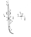
- the preferred embodiment of the present invention is depicted as a probe assembly 10 having a carrier 12, being generally cylindrical in form and sized to be longitudinally slidable through the interior of a steam generator conduit or the like.
- the carrier 12 is urged longitudinally through the conduit by urging means 14 shown in Figure 1 as being a flexible cable 14 which possesses sufficient longitudinal rigidity and strength to enable an operator located at one end of the conduit to insert and drive the probe 10 through any desired length.
- the cable 14 is additionally flexible transversely and the carrier 12 is also sized so as to permit the probe 10 to negotiate any curves or other obstructions which may be present in the subject conduit.
- sensor means 18 for determining the condition of at least a portion of the conduit wall currently being traversed.
- the sensors 18 are preferably selected from a group of sensors having direction measuring capabilities, thus confining the measurements to only a predetermined sector of the tube or conduit circumference. Such sensors include those utilizing magnetic eddy currents, ultrasonic radiation, visual inspection, or any other sensing means useful to determine the local condition of the conduit wall.
- Cable 14 may include one or more electrical conductors or other means for transferring sensor data between the sensors 18 and an external indicating or recording means (not shown).
- the sensors 18 are rotatable about a longitudinal axis 16 which coincides substantially with the longitudinal axis of the conduit being measured. This rotatability is achieved in the preferred embodiment by providing a rotatable coupling 13 between a cable portion 12a and a rotatable sensor portion 12b of the carrier 12.
- Alternative means for allowing rotation of the sensors 18 include a rotatable coupling (not shown) between the carrier 12 and cable 14, or by providing cable 14 with sufficient torsional flexibility for allowing the entire probe 10 to twist relatively freely.
- the present invention accomplishes this preferential alignment of the sensors 18 by the interaction of an elongated flat strip 20 and the curved conduit interior.
- the flat strip 20 is secured to the sensor portion 12b of the carrier and is composed of a resilient material which is additionally wear and corrosion resistant, such as nylon, polyethylene, or a tetrofluorocarbon compound.
- the flat strip 20 may be tapered about the front end 22 to facilitate insertion within the conduit.
- FIG. 2 shows a cross sectional view of the flat strip 20 as indicated in Figure 1, clearly showing transverse axes. 24 and 26 thereof.
- a member having a cross sectional area such as that of strip 20 possesses two significantly different bending moments with respect to transverse axes 24, 26.
- the bending moment about the first axis 24 is significantly greater than that about the second, perpendicular axis 26.
- these differing bending moments result in a member which is relatively inflexible about axis 24 and relatively easily flexible about axis 26.
- Figure 3 shows a probe according to the present invention in the process of traversing a curved section of conduit 28.
- Carrier 12 is pushed longitudinally through conduit 28 by means of the cable 14.
- Elongated strip 20, preceding the carrier 12 through the conduit 28 encounters the curved portion of the conduit and attempts to conform thereto.
- the flat strip 20 will twist both itself and the sensors 18 so as to minimize bending about transverse axis 24 and allow the probe assembly to slip freely along the interior of the conduit 28.
- transverse axis 24 now lies in the plane of curvature of the conduit 28 and results in alignment of sensor means 18 in the desired orientation.
- sensor means 18 would be adapted to scan both portions 30, 32 upon proper orientation-by the flat strip 20.
- the preferred embodiment of the present invention has the advantage of achieving the desired alignment in the curved portion of the conduit 28 without requiring intervention of the probe operator or any other complex orientation detecting means.
- the probe automatically aligns the sensors 18 upon entry into a curved portion and will realign itself as subsequent curved segments may be entered during a scanning traverse.
- a probe according to the present invention is equally useful for scanning curved conduits of any orientation and configuration, including elbow bends, subsequent bends in transverse directions, and other conduit configurations which may require the use of an oriented scanning probe.
Landscapes
- Physics & Mathematics (AREA)
- Chemical & Material Sciences (AREA)
- Engineering & Computer Science (AREA)
- Health & Medical Sciences (AREA)
- Immunology (AREA)
- Life Sciences & Earth Sciences (AREA)
- Analytical Chemistry (AREA)
- Biochemistry (AREA)
- General Health & Medical Sciences (AREA)
- General Physics & Mathematics (AREA)
- Pathology (AREA)
- Plasma & Fusion (AREA)
- General Engineering & Computer Science (AREA)
- High Energy & Nuclear Physics (AREA)
- Electrochemistry (AREA)
- Chemical Kinetics & Catalysis (AREA)
- Investigating Or Analyzing Materials By The Use Of Magnetic Means (AREA)
- Monitoring And Testing Of Nuclear Reactors (AREA)
- Investigating Or Analyzing Materials By The Use Of Ultrasonic Waves (AREA)
Applications Claiming Priority (2)
| Application Number | Priority Date | Filing Date | Title |
|---|---|---|---|
| US732999 | 1985-05-13 | ||
| US06/732,999 US4703264A (en) | 1985-05-13 | 1985-05-13 | Self-orienting conduit probe |
Publications (3)
| Publication Number | Publication Date |
|---|---|
| EP0201814A2 true EP0201814A2 (de) | 1986-11-20 |
| EP0201814A3 EP0201814A3 (en) | 1988-06-01 |
| EP0201814B1 EP0201814B1 (de) | 1991-02-27 |
Family
ID=24945793
Family Applications (1)
| Application Number | Title | Priority Date | Filing Date |
|---|---|---|---|
| EP86106020A Expired - Lifetime EP0201814B1 (de) | 1985-05-13 | 1986-05-02 | Sich selbst orientierende Rohrsonde |
Country Status (5)
| Country | Link |
|---|---|
| US (1) | US4703264A (de) |
| EP (1) | EP0201814B1 (de) |
| KR (1) | KR900002498B1 (de) |
| DE (1) | DE3677633D1 (de) |
| SE (1) | SE464596B (de) |
Cited By (2)
| Publication number | Priority date | Publication date | Assignee | Title |
|---|---|---|---|---|
| EP0710724A2 (de) | 1994-10-06 | 1996-05-08 | Akzo Nobel N.V. | Antigene von Toxoplasma gondii |
| WO1998030895A1 (en) * | 1997-01-08 | 1998-07-16 | Queen's University At Kingston | Method and apparatus for scanning a plurality of parallel pipes using tube-to-tube through transmission |
Families Citing this family (5)
| Publication number | Priority date | Publication date | Assignee | Title |
|---|---|---|---|---|
| US5060600A (en) * | 1990-08-09 | 1991-10-29 | Texas Utilities Electric Company | Condenser operation with isolated on-line test loop |
| WO1992002761A1 (en) * | 1990-08-09 | 1992-02-20 | Texas Utilities Electric Corporation | Condenser operation with isolated on-line test loop |
| US5174165A (en) * | 1990-08-13 | 1992-12-29 | Westinghouse Electric Corp. | Flexible delivery system for a rotatable probe |
| FR2671624B1 (fr) * | 1991-01-11 | 1995-03-31 | Ftelemecanique | Detecteur de proximite a tete orientable. |
| US5626445A (en) * | 1995-01-23 | 1997-05-06 | The United States Of America As Represented By The United States Department Of Energy | Tube cutter tool and method of use for coupon removal |
Family Cites Families (16)
| Publication number | Priority date | Publication date | Assignee | Title |
|---|---|---|---|---|
| US3149277A (en) * | 1959-06-04 | 1964-09-15 | Sun Oil Co | Borehole logging apparatus including flexible detector and weighting means |
| US3237093A (en) * | 1964-10-12 | 1966-02-22 | Sun Oil Co | Bore hole logging apparatus having rate of descent controlling means and a flexible cable member carrying a detector element |
| US3789511A (en) * | 1972-02-04 | 1974-02-05 | Columbia Gas Syst Service Corp | Apparatus for sensing a curvature in a conduit |
| US3916302A (en) * | 1973-11-12 | 1975-10-28 | Combustion Eng | Multi-coil eddy current probe for determining angular location of irregularity in cylindrical test member |
| US3906358A (en) * | 1973-11-12 | 1975-09-16 | Combustion Eng | Probe train including a flaw detector and a radiation responsive recording means with alignment means having a natural curved cast |
| GB1516307A (en) * | 1974-09-09 | 1978-07-05 | Babcock & Wilcox Ltd | Apparatus for conveying a device for inspecting or performing operations on the interior of a tube |
| GB1488833A (en) * | 1975-04-18 | 1977-10-12 | Atomic Energy Authority Uk | Non-destructive testing |
| JPS54121790A (en) * | 1978-03-15 | 1979-09-21 | Hitachi Ltd | In-pipe insertion type non-destructive inspector |
| DE2837488C2 (de) * | 1978-08-28 | 1980-08-28 | Kraftwerk Union Ag, 4330 Muelheim | Einrichtung zur Wirbelstromprüfung der Rohre von Wärmeaustauschern |
| US4303884A (en) * | 1978-10-19 | 1981-12-01 | Westinghouse Electric Corp. | Inflatable eddy current inspection probe for inspection of tubular means |
| US4241609A (en) * | 1979-04-09 | 1980-12-30 | Standard Oil Company (Indiana) | Tube internal measuring instrument |
| FR2461950A1 (fr) * | 1979-07-24 | 1981-02-06 | Radiologie Cie Gle | Sonde souple destinee au controle non destructif de tubes de grande longueur |
| US4319191A (en) * | 1980-01-10 | 1982-03-09 | Texaco Inc. | Dielectric well logging with radially oriented coils |
| SU903759A1 (ru) * | 1980-05-21 | 1982-02-07 | Кубанский Ордена Трудового Красного Знамени Сельскохозяйственный Институт | Матрица токовихревых накладных преобразователей |
| US4439831A (en) * | 1981-06-08 | 1984-03-27 | Schlumberger Technical Corporation | Digital induction logging system including autocalibration |
| NL181302C (nl) * | 1981-09-15 | 1987-07-16 | Nucon Eng & Contracting Bv | Inrichting voor het in het inwendige van een buisvormig lichaam beweegbaar dragen van inspectiemiddelen. |
-
1985
- 1985-05-13 US US06/732,999 patent/US4703264A/en not_active Expired - Fee Related
-
1986
- 1986-05-02 DE DE8686106020T patent/DE3677633D1/de not_active Expired - Fee Related
- 1986-05-02 EP EP86106020A patent/EP0201814B1/de not_active Expired - Lifetime
- 1986-05-09 KR KR1019860003606A patent/KR900002498B1/ko not_active Expired
- 1986-05-12 SE SE8602142A patent/SE464596B/sv not_active IP Right Cessation
Cited By (2)
| Publication number | Priority date | Publication date | Assignee | Title |
|---|---|---|---|---|
| EP0710724A2 (de) | 1994-10-06 | 1996-05-08 | Akzo Nobel N.V. | Antigene von Toxoplasma gondii |
| WO1998030895A1 (en) * | 1997-01-08 | 1998-07-16 | Queen's University At Kingston | Method and apparatus for scanning a plurality of parallel pipes using tube-to-tube through transmission |
Also Published As
| Publication number | Publication date |
|---|---|
| EP0201814B1 (de) | 1991-02-27 |
| EP0201814A3 (en) | 1988-06-01 |
| DE3677633D1 (de) | 1991-04-04 |
| SE8602142D0 (sv) | 1986-05-12 |
| KR900002498B1 (ko) | 1990-04-16 |
| KR860009439A (ko) | 1986-12-23 |
| SE464596B (sv) | 1991-05-13 |
| US4703264A (en) | 1987-10-27 |
| SE8602142L (sv) | 1986-11-14 |
Similar Documents
| Publication | Publication Date | Title |
|---|---|---|
| US5174164A (en) | Flexible cable | |
| EP1153289B1 (de) | Wirbelstromprüfung mit raumsparender konfiguration | |
| EP0242947B1 (de) | Untersuchung von Verteilerrohrlöchern | |
| EP0076144B1 (de) | Drehkopfprofilometerprobe | |
| JPH0232205A (ja) | 管内壁の輪郭検査方法及び装置 | |
| US4797613A (en) | Expandable eddy current probe for inspecting the interior of tubular conduits | |
| US3906358A (en) | Probe train including a flaw detector and a radiation responsive recording means with alignment means having a natural curved cast | |
| US20110125462A1 (en) | Tetherless tube inspection system | |
| US6100684A (en) | Helically traveling non-destructive system for the detection of cracks in pipelines | |
| US4703264A (en) | Self-orienting conduit probe | |
| EP0046079B1 (de) | Apparat zur Inspektion eines Wärmeaustauschrohres | |
| US5256966A (en) | Method for detecting flaws in a steam generator tube using a flexible eddy current probe having coil bank switching | |
| US4901578A (en) | Probe carrier drive assembly | |
| US4228593A (en) | Internal diameter measuring apparatus | |
| CA1197902A (en) | Apparatus for inspecting heat exchanger tubes | |
| US20200209198A1 (en) | Pig for inspecting a tubular object | |
| US5174165A (en) | Flexible delivery system for a rotatable probe | |
| JPH0238856A (ja) | 熱交換器の管の渦流探傷検査装置 | |
| US8794083B2 (en) | Low row steam generator inspection probe | |
| EP4411365A1 (de) | Vorrichtung zur inspektion der integrität eines inneren kanals unter verwendung eines magnetischen metallspeichers | |
| US5836199A (en) | Beaded shaft assembly | |
| US3911750A (en) | Apparatus for the internal inspection of tubular conduits | |
| JPS61213754A (ja) | 管の内部表面の検査装置 | |
| US4910877A (en) | Tube curvature measuring probe and method | |
| US6339327B1 (en) | Eddy current probe for inspecting electrically conducting parts |
Legal Events
| Date | Code | Title | Description |
|---|---|---|---|
| PUAI | Public reference made under article 153(3) epc to a published international application that has entered the european phase |
Free format text: ORIGINAL CODE: 0009012 |
|
| AK | Designated contracting states |
Kind code of ref document: A2 Designated state(s): BE DE FR NL |
|
| PUAL | Search report despatched |
Free format text: ORIGINAL CODE: 0009013 |
|
| AK | Designated contracting states |
Kind code of ref document: A3 Designated state(s): BE DE FR NL |
|
| 17P | Request for examination filed |
Effective date: 19881129 |
|
| RAP1 | Party data changed (applicant data changed or rights of an application transferred) |
Owner name: COMBUSTION ENGINEERING, INC. |
|
| 17Q | First examination report despatched |
Effective date: 19900423 |
|
| GRAA | (expected) grant |
Free format text: ORIGINAL CODE: 0009210 |
|
| AK | Designated contracting states |
Kind code of ref document: B1 Designated state(s): BE DE FR NL |
|
| PGFP | Annual fee paid to national office [announced via postgrant information from national office to epo] |
Ref country code: FR Payment date: 19910318 Year of fee payment: 6 |
|
| REF | Corresponds to: |
Ref document number: 3677633 Country of ref document: DE Date of ref document: 19910404 |
|
| PGFP | Annual fee paid to national office [announced via postgrant information from national office to epo] |
Ref country code: DE Payment date: 19910405 Year of fee payment: 6 |
|
| PGFP | Annual fee paid to national office [announced via postgrant information from national office to epo] |
Ref country code: BE Payment date: 19910424 Year of fee payment: 6 |
|
| ET | Fr: translation filed | ||
| PGFP | Annual fee paid to national office [announced via postgrant information from national office to epo] |
Ref country code: NL Payment date: 19910531 Year of fee payment: 6 |
|
| PLBE | No opposition filed within time limit |
Free format text: ORIGINAL CODE: 0009261 |
|
| STAA | Information on the status of an ep patent application or granted ep patent |
Free format text: STATUS: NO OPPOSITION FILED WITHIN TIME LIMIT |
|
| 26N | No opposition filed | ||
| PG25 | Lapsed in a contracting state [announced via postgrant information from national office to epo] |
Ref country code: BE Effective date: 19920531 |
|
| BERE | Be: lapsed |
Owner name: COMBUSTION ENGINEERING INC. Effective date: 19920531 |
|
| PG25 | Lapsed in a contracting state [announced via postgrant information from national office to epo] |
Ref country code: NL Effective date: 19921201 |
|
| NLV4 | Nl: lapsed or anulled due to non-payment of the annual fee | ||
| PG25 | Lapsed in a contracting state [announced via postgrant information from national office to epo] |
Ref country code: FR Effective date: 19930129 |
|
| PG25 | Lapsed in a contracting state [announced via postgrant information from national office to epo] |
Ref country code: DE Effective date: 19930202 |
|
| REG | Reference to a national code |
Ref country code: FR Ref legal event code: ST |