EP0201423A1 - Collapsible wheel chair with means for quick unbolting - Google Patents
Collapsible wheel chair with means for quick unbolting Download PDFInfo
- Publication number
- EP0201423A1 EP0201423A1 EP86400968A EP86400968A EP0201423A1 EP 0201423 A1 EP0201423 A1 EP 0201423A1 EP 86400968 A EP86400968 A EP 86400968A EP 86400968 A EP86400968 A EP 86400968A EP 0201423 A1 EP0201423 A1 EP 0201423A1
- Authority
- EP
- European Patent Office
- Prior art keywords
- bar
- slide
- chair
- rod
- holding
- Prior art date
- Legal status (The legal status is an assumption and is not a legal conclusion. Google has not performed a legal analysis and makes no representation as to the accuracy of the status listed.)
- Granted
Links
Images

Classifications
-
- A—HUMAN NECESSITIES
- A61—MEDICAL OR VETERINARY SCIENCE; HYGIENE
- A61G—TRANSPORT, PERSONAL CONVEYANCES, OR ACCOMMODATION SPECIALLY ADAPTED FOR PATIENTS OR DISABLED PERSONS; OPERATING TABLES OR CHAIRS; CHAIRS FOR DENTISTRY; FUNERAL DEVICES
- A61G5/00—Chairs or personal conveyances specially adapted for patients or disabled persons, e.g. wheelchairs
- A61G5/08—Chairs or personal conveyances specially adapted for patients or disabled persons, e.g. wheelchairs foldable
- A61G5/0808—Chairs or personal conveyances specially adapted for patients or disabled persons, e.g. wheelchairs foldable characterised by a particular folding direction
- A61G5/0816—Chairs or personal conveyances specially adapted for patients or disabled persons, e.g. wheelchairs foldable characterised by a particular folding direction folding side to side, e.g. reducing or expanding the overall width of the wheelchair
-
- A—HUMAN NECESSITIES
- A61—MEDICAL OR VETERINARY SCIENCE; HYGIENE
- A61G—TRANSPORT, PERSONAL CONVEYANCES, OR ACCOMMODATION SPECIALLY ADAPTED FOR PATIENTS OR DISABLED PERSONS; OPERATING TABLES OR CHAIRS; CHAIRS FOR DENTISTRY; FUNERAL DEVICES
- A61G5/00—Chairs or personal conveyances specially adapted for patients or disabled persons, e.g. wheelchairs
- A61G5/08—Chairs or personal conveyances specially adapted for patients or disabled persons, e.g. wheelchairs foldable
- A61G5/0891—Chairs or personal conveyances specially adapted for patients or disabled persons, e.g. wheelchairs foldable having rigid supports, e.g. seat or back supports which retain their shape after folding of the wheelchair
-
- Y—GENERAL TAGGING OF NEW TECHNOLOGICAL DEVELOPMENTS; GENERAL TAGGING OF CROSS-SECTIONAL TECHNOLOGIES SPANNING OVER SEVERAL SECTIONS OF THE IPC; TECHNICAL SUBJECTS COVERED BY FORMER USPC CROSS-REFERENCE ART COLLECTIONS [XRACs] AND DIGESTS
- Y10—TECHNICAL SUBJECTS COVERED BY FORMER USPC
- Y10T—TECHNICAL SUBJECTS COVERED BY FORMER US CLASSIFICATION
- Y10T403/00—Joints and connections
- Y10T403/32—Articulated members
- Y10T403/32254—Lockable at fixed position
- Y10T403/32426—Plural distinct positions
- Y10T403/32442—At least one discrete position
- Y10T403/32451—Step-by-step adjustment
- Y10T403/32459—Retainer extends through aligned recesses
-
- Y—GENERAL TAGGING OF NEW TECHNOLOGICAL DEVELOPMENTS; GENERAL TAGGING OF CROSS-SECTIONAL TECHNOLOGIES SPANNING OVER SEVERAL SECTIONS OF THE IPC; TECHNICAL SUBJECTS COVERED BY FORMER USPC CROSS-REFERENCE ART COLLECTIONS [XRACs] AND DIGESTS
- Y10—TECHNICAL SUBJECTS COVERED BY FORMER USPC
- Y10T—TECHNICAL SUBJECTS COVERED BY FORMER US CLASSIFICATION
- Y10T403/00—Joints and connections
- Y10T403/60—Biased catch or latch
- Y10T403/602—Biased catch or latch by separate spring
- Y10T403/604—Radially sliding catch
Definitions
- the present invention relates to a foldable armchair, in particular an armchair for the disabled, which comprises rapid unlocking means.
- a foldable chair comprising means for holding the chair in the unfolded position, which are foldable, means for locking in the unfolded position of these holding means, which comprise a bar; a slide mounted to slide - on said bar and coupled to said holding means so as to prevent the folding of these holding means when it occupies an extreme position along the bar, and to authorize this folding when it leaves this extreme position and slides along the bar, means for locking said slide in said extreme position, and corresponding unlocking means.
- the means for blocking the slide F can comprise a push button which penetrates into openings made in the bar C.
- the means for unlocking the slide they are not specified.
- the object of the invention is to provide a foldable chair of the type described above, which can be very easily unlocked for its folding.
- said unlocking means comprise a rod mounted mobile on the chair so as to be able to be brought into a position of cooperation with said locking means for unlocking said slide.
- said bar is hollow, said rod being disposed inside the bar so as to be able to slide longitudinally.
- said slide blocking means comprise an erasable lug carried by the slide and capable of projecting inside the bar through an opening arranged in line with said extreme position of the slide, the rod having an end arranged for push said lug out of the bar when it is moved along the bar.
- said rod is biased elastically in a direction opposite to said slide blocking means and is extended, at its end opposite to said blocking means, outside the bar by a pusher.
- the chair comprises two sides
- said means for holding the chair in the unfolded position comprise two connecting elements distant from each other by which said sides are connected to each other, each element of connection comprising two portions articulated relative to each other at a first common end, each portion being moreover connected in an articulated manner on one of said sides by its other end, said bar extending between said connecting elements and being hingedly connected to said common ends of the aforementioned portions, said slider being coupled to one of said connecting elements by means of two coupling elements which are each articulated by one end on said slider and by another end at l 'one of the points of articulation of said connecting element on the sides of the chair.
- said bar extends longitudinally relative to the chair. the end of said rod opposite to said locking means being turned towards the front of the fault
- the chair shown in the figures comprises two sidewalls 1, 2, parallel, on each of which are attached a rear wheel of large diameter 3.4 and a front wheel of small diameter 5.6.
- a "handrail" 7,8 is attached to each of the two rear wheels 3, 4.
- the vertical direction will be defined as being that perpendicular to the bearing plane of the wheels of the chair on the ground.
- Each flank 1,2 carries, at the front and at the rear and on the inside of the chair situated between the two flanks, a yoke 26, 27 and 28, 29 receiving a vertical axis 30, 31 and 32,33.
- the chair is foldable and has means for holding in the unfolded position which include. a front connecting element 9 and a rear connecting element 10 each consisting of two portions 11, 12 and 13, 14.
- the chair also comprises a bar 15 arranged in the median longitudinal plane of the chair, parallel to the sides 1,2.
- This bar carries in particular at each end a double yoke 16,17 each supporting two vertical axes 18, 19 and 20, 21.
- the two axes of each double yoke 16, 17 are arranged in a common plane perpendicular to the bar 15.
- a slide 22 On the bar 15 is slidably mounted a slide 22 which itself carries a double yoke 23 comprising two vertical aves 24, 25. These axes are. arranged in a common plane perpendicular to the bar 15.
- the two portions 11, 12 of the front connecting element 9 are respectively articulated, on the one hand on the axis 30, 32 of the adjacent flank 1,2 and on the other hand on the double front yoke 16 of the bar 15 , more precisely on the axis 18.19.
- the slider 22 is coupled to the rear connecting element 10 by means of two coupling elements 34, 35 which are respectively articulated, on the one hand on the axis 24.25 of the double yoke 23 of the slider 22 and d on the other hand on the axis 31, 33 of the adjacent flank 1,2.
- the sides 1,2, liaiso.n elements 9, 10 and the coupling elements 34,35 are, in this embodiment, rigid polygons which extend in vertical planes.
- the slider 22 occupies an extreme rear position along the bar 15 in which it is immobilized by means of locking means described below.
- the connecting element 10 then forms with the two coupling elements 34, 35 a non-deformable triangle keeping the two sides 1.2 of the chair separated from one another.
- the two portions 11, 12 and 13,14 of each connecting element extend in the extension of one another, perpendicular to the sides 1,2.
- a strap 36 is fixed by its two ends respectively to the portion 11 and to the portion 12 of the connecting element 9, in the vicinity of the bar 15, and makes it possible to pull the bar, which is directed towards the before, in order to unfold the chair again.
- the blocking means of the slide 22 will be specified with reference to FIG. 3.
- the bar 15 is a hollow cylindrical tube which has, at a determined location along the bar - namely at the right of said extreme rear position of the slide 22 - an opening 42 and, near its rear end, two opposite openings 43, 44.
- Le_coulisseau 22 comprises a cylindrical sleeve 45 which carries said double yoke 23 not visible on this fiqure, as well as a tubular extension 40 extending vertically downwards and opening inside the slide 22 by an opening 41 of a diameter .meter smaller than the inside diameter of said tubular extension 40.
- a cylindrical lug 46 is housed in the tubular extension 40 of the slide 22. It has a shoulder 47 in its median part and a rounded end 48 penetrating inside the conllisseau 22.
- a helical spring 49 is threaded on the other end 50 of the lug 46.
- the slide 22 thus equipped is fitted on the bar 15, the lug 46 being, to do this, pushes outwards from the conlisseau 22.
- the slide 22 is located at the opening 42 of the bar 15, the lug 46 plunges inside this opening: the slide is then blocked.
- the double front yoke 16 of the bar 15 is hollow and extended transversely by a tubular part 52.
- This tubular part 52 has a bottom 53 which has a central opening 54.
- the double front yoke 16 is fitted by its tubular part 52 in the end before the bar 15 and it is held there for example by gluing.
- the actual unlocking means comprise a rod 55 threaded over its entire length, which carries, near its rear end, an end piece 56.
- This end piece 56 is cylindrical and ends, at its end directed towards the rear of the chair, by a frustoconical part 57.
- the outside diameter of the end piece 56 is very slightly less than the inside diameter of the bar 15.
- the end piece 56 is axially threaded so that it can be screwed onto the rod 55. It is locked in a axial position along the rod by means of a lock nut 58.
- the rod 55 In the vicinity of its front end 61, the rod 55 is provided with a nut 59 locked in the axial position by a lock nut 60.
- the rod 55 thus equipped is threaded into the bar 15 by the rear end of the latter cf. It crosses the bottom 53 of the double front yoke 16, while the nut 59 and its lock nut 60 abut against this bottom.
- a helical spring 62 On the front end 61 of the rod 55 is threaded a helical spring 62, then a cap-shaped pusher 63 is screwed onto the rod 55.
- the spring 62 therefore bears on the bottom 53 and exerts a push on the pusher 63 , that is to say on the rod 55, this thrust being directed towards the front of the chair.
- the axial position of the endpiece 66 is adjusted so that the latter is flush, by its frustoconical part 57, with the lug 46.
- Abutment means are preferably provided so that when the chair is unfolded, it is immobilized in its unfolded position ( Figure 1), and does not risk folding back in the opposite direction.
- these abutment means comprise a tube 64 whose length is equal to the distance between the slide 22 - when it is blocked - and the rear end of the bar 15. This tube 64 externally covers the bar 15 and Therefore prevents the slide 22 from sliding further towards the rear of the bar 15, beyond its blocking position.
- the double rear yoke 17 of the bar 15 comprises a transverse tubular portion 66 by which it is introduced into the bar 15.
- the tube 64 and the double rear clevis 17 of the bar 15 are fixed to the latter by means of a bolt 65 transversely passing through the tube 64, the bar 15 and the tubular portion 66 of the double rear clevis 17.
- the user of the chair can unlock it by exerting a simple pressure on the pusher 63, directed towards the rear.
- the tip 57 ( Figure 3) then pushes back, through its frustoconical part 57 and then through its cylindrical part. the lug 46 inside the tubular extension 40 of the slide 22.
- the user must exert a push on the sides 1,2 of the chair tending to bring them closer to each other.
- This thrust on the sides 1, 2 tends to move the slide 22 forwards: the rounded end 48 of the lug 46 allows the latter to come out of the opening 42 of the bar 15.
- the chair is in a partially folded position.
- the knife 22 occupies a position 67 shown in phantom in FIG. 3.
- slide blocking means are such that it is not necessary to reset them after having unlocked: a simple push to move the two flanks 1,2 of the chair apart causes a new blocking.
- the rod 55 (FIG. 3) could, in a variant embodiment not shown, be controlled from the rear of the chair, and this, thanks to the symmetry of the locking means with respect to a plane perpendicular to the bar 15 and passing through the lug 46. It would suffice to turn all of the release means from the front to the rear, the rod extending into the bar from its rear end and the unblocking of the piston being caused by a push on the pusher, directed forwards.
- the invention is not limited to an armchair in which the rod 55 for unlocking the slide is located in the bar 15; it also relates to all variants in which the rod 55 is mounted movably on the chair 1 in a different manner, this rod can in any case be brought into a position of cooperation with means for releasing the slide.
Abstract
Description
La présente invention est relative à un fauteuil pliable, notamment un fauteuil pour handicapés, qui comprend des moyens de déverrouillage rapide.The present invention relates to a foldable armchair, in particular an armchair for the disabled, which comprises rapid unlocking means.
Elle concerne plus précisément un fauteuil pliable comprenant des moyens de maintien du fauteuil en position dépliée, qui sont pliables, des moyens de verrouillage en position dépliée de ces moyens de maintien, qui comprennent un barreau; un coulisseau monté à coulissement - sur ledit barreau et attelé auxdits moyens de maintien de façon à empêcher le repliement de ces moyens de maintien lorsqu'il occupe une position extrême le long du barreau, et à autoriser ce repliement lorsqu'il quitte cette position extrême et coulisse le long du barreau, des moyens de blocage dudit coulisseau dans ladite position extrême, et des moyens de déblocage correspondants.It relates more precisely to a foldable chair comprising means for holding the chair in the unfolded position, which are foldable, means for locking in the unfolded position of these holding means, which comprise a bar; a slide mounted to slide - on said bar and coupled to said holding means so as to prevent the folding of these holding means when it occupies an extreme position along the bar, and to authorize this folding when it leaves this extreme position and slides along the bar, means for locking said slide in said extreme position, and corresponding unlocking means.
Un tel fauteuil est par exemple connu par le document US-A-2 896 693. Les moyens de blocage du coulisseau F peuvent comprendre un bouton-poussoir qui pénètre dans des ouvertures pratiquées dans le barreau C. Quant aux moyens de déblocage du coulisseau, ils ne sont pas précisés.Such an armchair is for example known from document US-A-2 896 693. The means for blocking the slide F can comprise a push button which penetrates into openings made in the bar C. As for the means for unlocking the slide, they are not specified.
A priori, il y a lieu, pour débloquer le coulisseau en vue de replier le fauteuil, de manoeuvrer ledit bouton-poussoir. Or l'accès de ce bouton-poussoir qui est situé sous le siège du fauteuil, est malaisé pour l'utilisateur, notamment lorsqu'il s'agit d'un handicapé.A priori, it is necessary, to unlock the slide in order to fold the chair, to operate said push button. However, the access of this push-button which is located under the seat of the wheelchair is difficult for the user, in particular when it is a disabled person.
Le but de l'invention est de proposer un fauteuil pliable du type décrit ci-dessus, qui puisse être très facilement déverrouillé en vue de son repliement.The object of the invention is to provide a foldable chair of the type described above, which can be very easily unlocked for its folding.
Selon l'invention, lesdits moyens de déblocage comprennent une tige montée mobile sur le fauteuil de façon à pouvoir être amenée dans une position de coopération avec lesdits moyens de blocage pour débloquer ledit coulisseau.According to the invention, said unlocking means comprise a rod mounted mobile on the chair so as to be able to be brought into a position of cooperation with said locking means for unlocking said slide.
Avantagensement, ledit barreau est creux, ladite tige etant disposée à l'intérieur du barreau de façon à pouvoir coulisser longitudinalement.Advantageously, said bar is hollow, said rod being disposed inside the bar so as to be able to slide longitudinally.
De préférence, lesdits moyens de blocage du coulisseau comprennent un ergot effaçable porté par le coulisseau et pouvant faire saillie à l'intérieur du barreau au travers d'une ouverture disposée au droit de ladite position extrême du coulisseau, la tige présentant une extrémité agencée pour repousser ledit ergot hors du barreau lorsqu'elle est déplacée le long du barreau.Preferably, said slide blocking means comprise an erasable lug carried by the slide and capable of projecting inside the bar through an opening arranged in line with said extreme position of the slide, the rod having an end arranged for push said lug out of the bar when it is moved along the bar.
Avantageusement, ladite tige est rappelée élastiquement dans une direction opposée auxdits moyens de blocage du coulisseau et se prolonge, à son extrémité opposée auxdits moyens de blocage, à l'extérieur du barreau par un poussoir.Advantageously, said rod is biased elastically in a direction opposite to said slide blocking means and is extended, at its end opposite to said blocking means, outside the bar by a pusher.
Selon un mode de réalisation préféré du fauteuil, celui-ci comprend deux flancs, lesdits moyens de maintien du fauteuil en position dépliée comprennent deux éléments de liaison distants l'un de l'autre par lesquels lesdits flancs sont reliés entre eux, chaque élément de liaison comprenant deux portions articulées l'une par rapport à l'autre à une première extrémité commune, chaque portion étant par ailleurs reliée de façon articulée sur l'un desdits flancs par son autre extrémité, Ledit barreau s'étendant entre lesdits éléments de liaison et étant relié de façon articulée auxdites extrémités communes des portions susdites, ledit coulisseau étant attelé à l'un desdits éléments de liaison au moyen de deux éléments d'attelage qui sont articulés chacun par une extrémité sur ledit coulisseau et par une autre extrémité à l'un des points d'articulation dudit élément de Liaison sur les flancs du fauteuil.According to a preferred embodiment of the chair, it comprises two sides, said means for holding the chair in the unfolded position comprise two connecting elements distant from each other by which said sides are connected to each other, each element of connection comprising two portions articulated relative to each other at a first common end, each portion being moreover connected in an articulated manner on one of said sides by its other end, said bar extending between said connecting elements and being hingedly connected to said common ends of the aforementioned portions, said slider being coupled to one of said connecting elements by means of two coupling elements which are each articulated by one end on said slider and by another end at l 'one of the points of articulation of said connecting element on the sides of the chair.
De préférence, ledit barreau s'étend longitudinalement par rapport au fauteuil. l'extrémité de ladite tige opposée auxdits moyens de blocage étant tournée vers l'avant du fauteui1Preferably, said bar extends longitudinally relative to the chair. the end of said rod opposite to said locking means being turned towards the front of the fault
D'autres détails et avantages de l'invention apparaitront au couros de la description qui suit, d'un mode de réalisation donne à titre d'exemple non limitatif.Other details and advantages of the invention will appear in the course of the description which follows, of an embodiment given by way of nonlimiting example.
en regard des dessins annexés parmi lesquels :
- - la figure 1 est une vue de dessus d'un fauteuil pliable selon l'invention, en position dépliée ;
- - la figure 2 est une vue de dessus du fauteuil de la
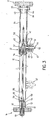
fiqure 1, en position partiellement repliée, et ; - - la figure 3 est une vue partielle en coupe longitudinale agrandie, selon la ligne III-III de la figure 1.
- - Figure 1 is a top view of a foldable chair according to the invention, in the unfolded position;
- - Figure 2 is a top view of the chair of the
fiqure 1, in partially folded position, and; - - Figure 3 is a partial view in enlarged longitudinal section, along the line III-III of Figure 1.
Le fauteuil représenté sur les figures comprend deux flancs 1, 2, parallèles,sur chacun desquels sont rapportées une roue arrière de grand diamètre 3,4 et une roue avant de petit diamètre 5,6. Une "main courante" 7,8 est rapportée sur chacune des deux roues arrière 3, 4. Dans ce qui suit, la direction verticale sera définie comme étant celle perpendiculaire au plan d'appui des roues du fauteuil sur le sol.The chair shown in the figures comprises two
Chaque flanc 1,2 porte, à l'avant et à l'arrière et du côté intérieur du fauteuil situé entre les deux flancs, une chape 26, 27 et 28, 29 recevant un axe vertical 30, 31 et 32,33.Each
Le fauteuil est pliable et présente des moyens de maintien en position dépliée qui comprennent. un élément de Liaison avant 9 et un élément de liaison arriére 10 constitués chacun de deux portions 11, 12 et 13,14.The chair is foldable and has means for holding in the unfolded position which include. a
Le fauteuil comprend encore un barreau 15 disposé dans Le plan longitudinal médian du fauteuil, parallèlement aux flancs 1,2. Ce barreau porte notamment à chaque extrémité une double chape 16,17 supportant chacune deux axes verticaux 18, 19 et 20, 21. Les deux axes de chaque double chape 16, 17 sont disposés dans un plan commun perpendiculaire au barreau 15.The chair also comprises a
Sur le barreau 15 est monté à coulissement un coulisseau 22 qui porte lui-même une double chape 23 comportant deux aves verticaux 24, 25. Ces axes sont. disposés dans un plan commun perpendiculaire au barreau 15.On the
Les deux portions 11, 12 de l'élément de liaison avant 9 sont respectivement articulées, d'une part sur l'axe 30, 32 du flanc adjacent 1,2 et d'autre part sur la double chape-avant 16 du barreau 15, plus précisément sur l'axe 18,19.The two
Il en va de même pour les deux portions 13,14 de l'élément de liaison arrière 10 qui sont respectivement articulées sur l'axe 31,33 du flanc adjacent et d'autre part sur l'axe 20,21 de la double chape arrière 17 du barreau 15.The same goes for the two
Le coulisseau 22 est attelé à l'élément de liaison arrière 10 au moyen de deux éléments d'attelage 34, 35 qui sont respectivement articulés, d'une part sur l'axe 24,25 de la double chape 23 du coulisseau 22 et d'autre part sur l'axe 31, 33 du flanc adjacent 1,2.The
Les flancs 1,2 , les éléments de liaiso.n 9, 10 et les éléments d'attelage 34,35 sont, dans cet exemple de réalisation, des polygones rigides qui s'étendent dans des plans verticaux.The
Tel que représenté sur la figure 1, le coulisseau 22 occupe une position extrême arrière le long du barreau 15 dans laquelle il est immobilisé grâce à des moyens de blocage décrits ci-après. L'élément de liaison 10 forme alors avec les deux éléments d'attelage 34,35 un triangle indéformable maintenant les deux flancs 1,2 du fauteuil écartés l'un de l'autre. Les deux portions 11, 12 et 13,14 de chaque élément de liaison s'étendent dans le prolongement l'une de l'autre, perpendiculairement aux flancs 1,2.As shown in Figure 1, the
Lorsque le coulisseau 22 est débloqué de la façon décrite ci-après, l'utilisateur peut rapprocher manuellement l'un de l'autre les deux flanes 1, 2 du fauteuil, en poussant le barreau 15 vers l'arrière, le coulisseau 22 se déplaçant vers l'avant (figure 2) jusque une position dans laquelle les deux flanes 1, 2 sont juxtaposes.When the
Une sangle 36 est fixée par ses deux extrémités respectivement sur La portion 11 et sur la portion 12 de l'élément de liaison 9, au voisinage du barreau 15, et permet d'effectuer une traction sur le barreau, qui est dirigée vers l'avant, en vue de déplier à nouveau le fauteuil.A
Les moyens de blocage du coulisseau 22 vont être précisés en regard de la figure 3. Le barreau 15 est un tube cylindrique creux qui possède, en un endroit déterminé le long du barreau -à savoir au droit de ladite position extrême arrière du coulisseau 22- une ouverture 42 et, au voisinage de son extrémité arrière, deux ouvertures opposées 43, 44.The blocking means of the
Le_coulisseau 22 comprend une douille cylindrique 45 qui porte ladite double chape 23 non visible sur cette fiqure, ainsi qu'un prolongement tubulaire 40 s'étendant verticalement vers le bas et débouchant à l'intérieur du coulisseau 22 par une ouverture 41 d'un dia.mètre plus petit que le diamètre intérieur dudit prolonqement tubuLaire 40.Le_coulisseau 22 comprises a
Un ergot cylindrique 46 est logé dans le proLongement tubulaire 40 du coulisseau 22. Il présente un épaulement 47 dans sa partie médiane et une extrémité arrondi.e 48 pénétrant à l'intérieur du conllisseau 22.A
Un ressort hélicoïdal 49 est enfilé sur l'autre extrémité 50 de l'ergot 46. Un chapeau 51 au travers duquel passe ladite autre extrémité 50, coiffe Le prolongement tubulaire 40.A
Ainsi, le ressort 49 s'appuyant d'une part sur Le chapeau 51 et d'autre part sur l'épaulement 47 de l'ergot 46, ledit ergot est rappelé élastiquement vers l'intérieur du coulisseau.Thus, the
Le coulisseau 22 ainsi équipé est emmanché sur le barreau 15, l'ergot 46 étant, pour ce faire, repousse vers l'extérieur du conlisseau 22. Lorsque le coulisseau 22 se trouve au droit de l'ouverture 42 du barreau 15, l'ergot 46 plonge à l'intérieur de cette ouverture : le coulisseau est alors bloqué.The
Les moyens de déblocage du coulisseau 22 vont maintenant être explicités. La double chape avant 16 du barreau 15 est creuse et prolongée transversalement par une partie tubulaire 52. Cette partie tubulaire 52 comporte un fond 53 qui présente une ouverture centrale 54. La double chape avant 16 est emmanchée par sa partie tubulaire 52 dans l'extrémité avant du barreau 15 et elle y est maintenue par exemple par collage.The means for unlocking the
Les moyens de déblocage proprement dits comprennent une tige 55 filetée sur toute sa longueur, qui porte, au voisinage de son extrémité arrière, un embout 56. Cet embout 56 est cylindrique et se termine, à son extrémité dirigée vers l'arrière du fauteuil, par une partie tronconique 57. Le diamètre extérieur de l'embout 56 est très légèrement inférieur au diamètre intérieur du barreau 15. L'embout 56 est taraudé axialement de façon qu'il puisse être vissé sur la tige 55. Il est bloqué dans une position axiale le long de la tige au moyen d'un contre-écrou 58.The actual unlocking means comprise a
Au voisinage de son extrémité avant 61, la tige 55 est munie d'un écrou 59 bloqué en position axiale par un contre-écrou 60. La tige 55 ainsi équipée est enfillée dans le barreau 15 par l'extrémité arrière de celui- cf. Elle traverse Le fond 53 de la double chape avant 16, tandis que l'écrou 59 et son contre-écrou 60 butent contre ce fond.In the vicinity of its
Sur l'extrémité avant 61 de la tige 55 est enfilé un ressort hélicoidal 62, puis un poussoir en forme de capuchon 63 est vissé sur La tige 55. Le ressort 62 prend donc appui sur le fond 53 et exerce une poussée sur le poussoir 63, c'est-à-dire sur La tige 55, cette poussée étant dirigée vers l'avant du fauteuil. La position axiale de l'embout 66 est réglée de façon que celui-ci affleure, par sa partie tronconique 57, l'ergot 46.On the
Des moyens de butée sont de préférence prévus pour que, lorsque l'on déplie le fauteuil, celui-ci soit immobilisé dans sa position dépliée (figure 1), et ne risque pas de se replier en sens inverse. Dans cet exemple de réalisation, ces moyens de butée comprennent un tube 64 dont la longueur est égale à la distance entre le coulisseau 22 -quand il est bloqué- et l'extrémité arrière du barreau 15. Ce tube 64 coiffe extérieurement le barreau 15 et empêche donc le coulisseau 22 de glisser davantage vers l'arrière du barreau 15, au-delà de sa position de blocage.Abutment means are preferably provided so that when the chair is unfolded, it is immobilized in its unfolded position (Figure 1), and does not risk folding back in the opposite direction. In this exemplary embodiment, these abutment means comprise a
La double chape arrière 17 du barreau 15 comprend une portion tubulaire transversale 66 par laquelle elle est introduite dans le barreau 15.The double
Le-tube 64 et la double chape arrière 17 du barreau 15 sont fixés sur celui-ci au moyen d'un boulon 65 traversant transversalement le tube 64, le barreau 15 et la portion tubulaire 66 de la double chape arrière 17.The
En utilisation, le fauteuil se trouvant verrouillé en position dépliée (figures 1 et 3), l'utilisateur du fauteuil peut déverrouiller celui-ci en exerçant une simple pression sur le poussoir 63, dirigée vers l'arrière. L'embout 57 (figure 3) repousse alors, par sa partie tronconique 57 puis par sa partie cylindrique. l'ergot 46 à l' intérieur du prolongement tubulaire 40 du coulisseau 22. Dans le même temps, l'utilisateur doit exercer une poussée sur les flancs 1,2 du fauteuil tendant à rapprocher ceux-ci l'un de l'autre. Cette poussée sur les flancs 1, 2 tend à déplacer le coulisseau 22 vers l'avant : l'extrémité arrondie 48 de l'ergot 46 permet à ce dernier de sortir de l'ouverture 42 du barreau 15. Tel que représenté en figure 2, le fauteuil est dans une position de repliement partiel. En fin de repliement du fauteuil, le coutisseau 22 occupe une position 67 représentée en traits mixtes sur la figure 3.In use, the chair being locked in the unfolded position (Figures 1 and 3), the user of the chair can unlock it by exerting a simple pressure on the
Pour déplier à nouveau le fauteuil, il suffit à l'utilisateur d'écarter manuellement les deux flances 1,2, ce qui a pour effet de faire coulisser le coulisseau 22 vers sa position arrière de blocage. Dès que le coulisseau 22 bute contre Le tube 64, son ergot 46 se trouve au droit de l'ouverture 42 du barreau 15 et plonge dans le barreau pour bloquer le coulisseau 22.To unfold the chair again, the user just has to manually separate the two
On notera que les moyens de blocage du coulisseau sont tels qu'il n'est pas nécessaire de les réarmer après avoir procédé au déblocage : une simple poussée pour écarter les deux flancs 1,2 du fauteuil provoque un nouveau blocage.Note that the slide blocking means are such that it is not necessary to reset them after having unlocked: a simple push to move the two
Par ailleurs, il y a lieu de constater que la tige 55 (figure 3) pourrait, dans une variante de réalisation non représentée, être commandée depuis l'arrière du fauteuil, et ce, grâce à la symétrie des moyens de blocage par rapport à un plan perpendiculaire au barreau 15 et passant par l'ergot 46. Il suffirait de retourner l'ensemble des moyens de déblocage de l'avant vers l'arrière, la tige s'étendant dans le barreau à partir de son éxtré- mité arrière et le déblocage du cculisseau étant provoqué par une poussée sur le poussoir, dirigée vers l'avant.Furthermore, it should be noted that the rod 55 (FIG. 3) could, in a variant embodiment not shown, be controlled from the rear of the chair, and this, thanks to the symmetry of the locking means with respect to a plane perpendicular to the
Naturellement, l'invention n'est pas limitée à un fauteuil dans Lequel la tige 55 de déblocage du coulisseau est située dans le barreau 15 ; elle concerne aussi toutes variantes dans lesquelles la tige 55 est montée mobile sur le fauteuil 1 d'une manière différente, cette tige pouvant dans tous les cas être amenée dans une position de coopération avec des moyens de déblocage du coulisseau.Naturally, the invention is not limited to an armchair in which the
Claims (7)
Priority Applications (1)
| Application Number | Priority Date | Filing Date | Title |
|---|---|---|---|
| AT86400968T ATE56613T1 (en) | 1985-05-06 | 1986-05-05 | FOLDABLE WHEELCHAIR WITH QUICK RELEASE MEANS. |
Applications Claiming Priority (2)
| Application Number | Priority Date | Filing Date | Title |
|---|---|---|---|
| FR8506842A FR2581299B1 (en) | 1985-05-06 | 1985-05-06 | DEVICE FOR LOCKING AND UNLOCKING A FOLDABLE ARMCHAIR, IN PARTICULAR A ARMCHAIR FOR THE DISABLED |
| FR8506842 | 1985-05-06 |
Publications (2)
| Publication Number | Publication Date |
|---|---|
| EP0201423A1 true EP0201423A1 (en) | 1986-11-12 |
| EP0201423B1 EP0201423B1 (en) | 1990-09-19 |
Family
ID=9318980
Family Applications (1)
| Application Number | Title | Priority Date | Filing Date |
|---|---|---|---|
| EP86400968A Expired - Lifetime EP0201423B1 (en) | 1985-05-06 | 1986-05-05 | Collapsible wheel chair with means for quick unbolting |
Country Status (6)
| Country | Link |
|---|---|
| US (1) | US4712830A (en) |
| EP (1) | EP0201423B1 (en) |
| JP (1) | JPS6257522A (en) |
| AT (1) | ATE56613T1 (en) |
| DE (1) | DE3674241D1 (en) |
| FR (1) | FR2581299B1 (en) |
Cited By (2)
| Publication number | Priority date | Publication date | Assignee | Title |
|---|---|---|---|---|
| US6572133B1 (en) * | 2001-01-18 | 2003-06-03 | Sunrise Medical Hhg, Inc. | Folding mechanism for a wheelchair |
| CN107137185A (en) * | 2017-05-31 | 2017-09-08 | 常州高尔登科技有限公司 | Folding wheel chair and its locking device |
Families Citing this family (23)
| Publication number | Priority date | Publication date | Assignee | Title |
|---|---|---|---|---|
| US4863181A (en) * | 1988-05-31 | 1989-09-05 | Howle Edward S | Foldable wheelchair |
| DE3902424A1 (en) * | 1989-01-27 | 1990-08-02 | Uwe Kleinschmidt | Wheelchair for the disabled, having removable disc wheels, wheel forks, foot part, seat shell and folding kinematics moving in horizontal planes |
| US4971342A (en) * | 1989-11-13 | 1990-11-20 | Albert Dix | Animal figure velocipede |
| US5078349A (en) * | 1990-04-16 | 1992-01-07 | Midmark Corporation | Locking mechanism for an IV pole |
| US5352057A (en) * | 1992-12-28 | 1994-10-04 | Zody Charles R | Adjustment tool for telescoping members |
| JP3311160B2 (en) * | 1994-08-19 | 2002-08-05 | アップリカ▲葛▼西株式会社 | Baby carriage seat |
| JP3311163B2 (en) * | 1994-09-21 | 2002-08-05 | アップリカ▲葛▼西株式会社 | Stroller and method of manufacturing seat plate for its seat |
| US6164674A (en) * | 1995-06-05 | 2000-12-26 | Adorno/Rogers Technology, Inc. | Adjustable wheelbase wheelchair |
| US6499762B1 (en) | 1995-06-05 | 2002-12-31 | Adorno/Rogers Technology, Inc. | Frame support apparatus and coupling device for use with an ambulatory system and method of fabrication thereof |
| DE19733453A1 (en) | 1997-08-02 | 1999-02-04 | Jens Lueck | Foldable wheelchair |
| NO311555B1 (en) * | 2000-02-09 | 2001-12-10 | Stefan Solberg | Wheelchair for electric wheelchair |
| US6394476B1 (en) | 2000-08-10 | 2002-05-28 | Invacare Corporation | Wheelchair seat having adjustable telescoping assembly |
| US6467788B1 (en) * | 2001-06-04 | 2002-10-22 | Tianfu Li | Tilt-in-place wheelchair having adjustable wheelbase width |
| EP1454606A1 (en) * | 2003-03-07 | 2004-09-08 | Vassilli s.r.l. | Foldable wheelchair |
| US7607724B2 (en) * | 2006-08-16 | 2009-10-27 | Promen-Aid Innovations Ltd. | Collapsible support structure |
| US7607725B2 (en) * | 2006-08-16 | 2009-10-27 | Promen-Aid Innovations Ltd. | Collapsible support structure |
| JP5301342B2 (en) * | 2009-04-21 | 2013-09-25 | アップリカ・チルドレンズプロダクツ株式会社 | Folding wheelbarrow |
| US8496289B2 (en) * | 2011-10-05 | 2013-07-30 | Shin Fang Plastic Industrial Co., Ltd. | Foldable frame structure |
| EP2879641B9 (en) * | 2012-07-31 | 2016-12-21 | Invacare International Sàrl | Foldable wheelchair frame including a self locking device |
| EP3041446A4 (en) * | 2013-09-06 | 2017-08-23 | Alu Rehab As | Folding mechanism for a folding wheelchair, backrest post for wheelchair and wheelchair |
| JP6111405B2 (en) * | 2014-05-28 | 2017-04-12 | オンウェー株式会社 | Folding frame |
| CN104367019A (en) * | 2014-10-22 | 2015-02-25 | 天津市仟佰億家具有限公司 | Seat convenient to fold and store |
| DE102016109759A1 (en) * | 2016-05-02 | 2017-11-02 | Otto Bock Mobility Solutions Gmbh | Foldable mobility aid |
Citations (7)
| Publication number | Priority date | Publication date | Assignee | Title |
|---|---|---|---|---|
| DE62842C (en) * | G. LINDER in Weyer, Rheinland | Rod tip lock with device for releasing the opened umbrella | ||
| US2592405A (en) * | 1948-06-14 | 1952-04-08 | Herbert A Everest | Collapsible commode chair |
| US2896693A (en) * | 1953-04-07 | 1959-07-28 | Adam Wilhelm Lehr | Foldable invalid or bath chair |
| US4026568A (en) * | 1976-02-23 | 1977-05-31 | Beverly Grant Rutledge Hallam | Triple hinged folding T frame wheelchair |
| US4065180A (en) * | 1977-01-05 | 1977-12-27 | John Karay | Leg-restraining device for geriatric chair |
| GB2125740A (en) * | 1982-08-25 | 1984-03-14 | Bencraft Ltd | A collapsible wheelchair |
| WO1985001205A1 (en) * | 1983-09-15 | 1985-03-28 | Composites Aquitaine | Invalid chair based on composite materials |
Family Cites Families (4)
| Publication number | Priority date | Publication date | Assignee | Title |
|---|---|---|---|---|
| US1748426A (en) * | 1927-10-10 | 1930-02-25 | Pentland Moses | Automobile safety attachment |
| US2639162A (en) * | 1949-05-17 | 1953-05-19 | Schon Leo | Collapsible carriage |
| US3507528A (en) * | 1965-02-16 | 1970-04-21 | Westinghouse Electric Corp | Locking device |
| US4390300A (en) * | 1980-08-21 | 1983-06-28 | Foster Edwin E | Adjustable bicycle handlebar stem |
-
1985
- 1985-05-06 FR FR8506842A patent/FR2581299B1/en not_active Expired
-
1986
- 1986-05-05 US US06/859,580 patent/US4712830A/en not_active Expired - Fee Related
- 1986-05-05 AT AT86400968T patent/ATE56613T1/en not_active IP Right Cessation
- 1986-05-05 EP EP86400968A patent/EP0201423B1/en not_active Expired - Lifetime
- 1986-05-05 DE DE8686400968T patent/DE3674241D1/en not_active Expired - Fee Related
- 1986-05-06 JP JP61103708A patent/JPS6257522A/en active Pending
Patent Citations (7)
| Publication number | Priority date | Publication date | Assignee | Title |
|---|---|---|---|---|
| DE62842C (en) * | G. LINDER in Weyer, Rheinland | Rod tip lock with device for releasing the opened umbrella | ||
| US2592405A (en) * | 1948-06-14 | 1952-04-08 | Herbert A Everest | Collapsible commode chair |
| US2896693A (en) * | 1953-04-07 | 1959-07-28 | Adam Wilhelm Lehr | Foldable invalid or bath chair |
| US4026568A (en) * | 1976-02-23 | 1977-05-31 | Beverly Grant Rutledge Hallam | Triple hinged folding T frame wheelchair |
| US4065180A (en) * | 1977-01-05 | 1977-12-27 | John Karay | Leg-restraining device for geriatric chair |
| GB2125740A (en) * | 1982-08-25 | 1984-03-14 | Bencraft Ltd | A collapsible wheelchair |
| WO1985001205A1 (en) * | 1983-09-15 | 1985-03-28 | Composites Aquitaine | Invalid chair based on composite materials |
Cited By (2)
| Publication number | Priority date | Publication date | Assignee | Title |
|---|---|---|---|---|
| US6572133B1 (en) * | 2001-01-18 | 2003-06-03 | Sunrise Medical Hhg, Inc. | Folding mechanism for a wheelchair |
| CN107137185A (en) * | 2017-05-31 | 2017-09-08 | 常州高尔登科技有限公司 | Folding wheel chair and its locking device |
Also Published As
| Publication number | Publication date |
|---|---|
| EP0201423B1 (en) | 1990-09-19 |
| FR2581299B1 (en) | 1988-07-15 |
| FR2581299A1 (en) | 1986-11-07 |
| JPS6257522A (en) | 1987-03-13 |
| DE3674241D1 (en) | 1990-10-25 |
| US4712830A (en) | 1987-12-15 |
| ATE56613T1 (en) | 1990-10-15 |
Similar Documents
| Publication | Publication Date | Title |
|---|---|---|
| EP0201423B1 (en) | Collapsible wheel chair with means for quick unbolting | |
| EP2531393B1 (en) | Extensible two-wheeled vehicle | |
| EP3156311B1 (en) | Wheeled vehicle, notably for children | |
| EP2244924B1 (en) | Stroller frame, particularly for transporting a child | |
| EP3233617B1 (en) | Collapsible scooter vehicle | |
| FR3003801A1 (en) | STROLLER FOR CHILDREN TRANSFORMABLE IN TRAILER FOR BIKE | |
| FR2761328A3 (en) | FOLDABLE BABY STROLLER | |
| WO2020008132A1 (en) | Compact foldable kick scooter | |
| FR2515128A1 (en) | MECHANISM FOR CHANGING THE DIRECTION OF ORIENTATION OF THE PUSH HANDLES OF A BABY STROLLER AND STROLLER EQUIPPED WITH SUCH A MECHANISM | |
| FR2677623A1 (en) | CONTAINER WITH RETRACTABLE STANDS IN THE SIDE SIDES. | |
| FR2615799A1 (en) | Seat bench particularly for the rear seat for motor vehicles | |
| WO2010149883A1 (en) | Telescopic cane intended mainly for disabled persons | |
| EP0201424B1 (en) | Chair for handicapped persons with a device for quickly fastening the footrests | |
| EP3781443B1 (en) | Roof-bar assembly intended to be positioned on a vehicle roof | |
| EP2714500B1 (en) | Wheeled vehicle such as a scooter | |
| WO2021156281A1 (en) | Foldable two-wheeled vehicle with reduced size in the folded position | |
| FR2561725A1 (en) | Assembly system with articulation and application for producing folding tables or shelves | |
| FR2845877A1 (en) | Seat base comprises column pivoted on cruciform sleeve which slides along bar forming two wheeled feet with, other two feet being attached to sleeve by pivots, so that base can be folded down parallel to bar | |
| FR2558056A1 (en) | Stretcher with retractable feet for loading in an ambulance | |
| WO2022043618A1 (en) | Three-wheeled foldable pushchair | |
| FR3136221A1 (en) | Foldable scooter | |
| FR3101604A1 (en) | FOLDABLE SCOOTER | |
| FR2700515A1 (en) | Folding pushchair or carriage assembly | |
| FR3101605A1 (en) | FOLDABLE SCOOTER | |
| FR2623137A1 (en) | Device for tightening and loosening a vehicle wheel nut |
Legal Events
| Date | Code | Title | Description |
|---|---|---|---|
| PUAI | Public reference made under article 153(3) epc to a published international application that has entered the european phase |
Free format text: ORIGINAL CODE: 0009012 |
|
| AK | Designated contracting states |
Kind code of ref document: A1 Designated state(s): AT BE CH DE FR GB IT LI LU NL SE |
|
| 17P | Request for examination filed |
Effective date: 19870506 |
|
| 17Q | First examination report despatched |
Effective date: 19881209 |
|
| GRAA | (expected) grant |
Free format text: ORIGINAL CODE: 0009210 |
|
| AK | Designated contracting states |
Kind code of ref document: B1 Designated state(s): AT BE CH DE FR GB IT LI LU NL SE |
|
| PG25 | Lapsed in a contracting state [announced via postgrant information from national office to epo] |
Ref country code: SE Effective date: 19900919 Ref country code: AT Effective date: 19900919 |
|
| REF | Corresponds to: |
Ref document number: 56613 Country of ref document: AT Date of ref document: 19901015 Kind code of ref document: T |
|
| ITF | It: translation for a ep patent filed |
Owner name: JACOBACCI & PERANI S.P.A. |
|
| GBT | Gb: translation of ep patent filed (gb section 77(6)(a)/1977) | ||
| REF | Corresponds to: |
Ref document number: 3674241 Country of ref document: DE Date of ref document: 19901025 |
|
| PG25 | Lapsed in a contracting state [announced via postgrant information from national office to epo] |
Ref country code: LU Free format text: LAPSE BECAUSE OF NON-PAYMENT OF DUE FEES Effective date: 19910531 Ref country code: LI Effective date: 19910531 Ref country code: CH Effective date: 19910531 |
|
| PLBE | No opposition filed within time limit |
Free format text: ORIGINAL CODE: 0009261 |
|
| STAA | Information on the status of an ep patent application or granted ep patent |
Free format text: STATUS: NO OPPOSITION FILED WITHIN TIME LIMIT |
|
| 26N | No opposition filed | ||
| REG | Reference to a national code |
Ref country code: CH Ref legal event code: PL |
|
| PGFP | Annual fee paid to national office [announced via postgrant information from national office to epo] |
Ref country code: FR Payment date: 19930420 Year of fee payment: 8 |
|
| PGFP | Annual fee paid to national office [announced via postgrant information from national office to epo] |
Ref country code: BE Payment date: 19930427 Year of fee payment: 8 |
|
| PGFP | Annual fee paid to national office [announced via postgrant information from national office to epo] |
Ref country code: GB Payment date: 19930428 Year of fee payment: 8 |
|
| PGFP | Annual fee paid to national office [announced via postgrant information from national office to epo] |
Ref country code: DE Payment date: 19930527 Year of fee payment: 8 |
|
| ITTA | It: last paid annual fee | ||
| PG25 | Lapsed in a contracting state [announced via postgrant information from national office to epo] |
Ref country code: GB Effective date: 19940505 |
|
| PG25 | Lapsed in a contracting state [announced via postgrant information from national office to epo] |
Ref country code: BE Effective date: 19940531 |
|
| PGFP | Annual fee paid to national office [announced via postgrant information from national office to epo] |
Ref country code: NL Payment date: 19940531 Year of fee payment: 9 |
|
| BERE | Be: lapsed |
Owner name: S.A. ETS POIRIER Effective date: 19940531 Owner name: COMPOSITES AQUITAINE Effective date: 19940531 |
|
| GBPC | Gb: european patent ceased through non-payment of renewal fee |
Effective date: 19940505 |
|
| PG25 | Lapsed in a contracting state [announced via postgrant information from national office to epo] |
Ref country code: FR Effective date: 19950131 |
|
| PG25 | Lapsed in a contracting state [announced via postgrant information from national office to epo] |
Ref country code: DE Effective date: 19950201 |
|
| REG | Reference to a national code |
Ref country code: FR Ref legal event code: ST |
|
| PG25 | Lapsed in a contracting state [announced via postgrant information from national office to epo] |
Ref country code: NL Effective date: 19951201 |
|
| NLV4 | Nl: lapsed or anulled due to non-payment of the annual fee |
Effective date: 19951201 |
|
| PG25 | Lapsed in a contracting state [announced via postgrant information from national office to epo] |
Ref country code: IT Free format text: LAPSE BECAUSE OF NON-PAYMENT OF DUE FEES;WARNING: LAPSES OF ITALIAN PATENTS WITH EFFECTIVE DATE BEFORE 2007 MAY HAVE OCCURRED AT ANY TIME BEFORE 2007. THE CORRECT EFFECTIVE DATE MAY BE DIFFERENT FROM THE ONE RECORDED. Effective date: 20050505 |