EP0201106A2 - Codeur absolu de position - Google Patents
Codeur absolu de position Download PDFInfo
- Publication number
- EP0201106A2 EP0201106A2 EP86106353A EP86106353A EP0201106A2 EP 0201106 A2 EP0201106 A2 EP 0201106A2 EP 86106353 A EP86106353 A EP 86106353A EP 86106353 A EP86106353 A EP 86106353A EP 0201106 A2 EP0201106 A2 EP 0201106A2
- Authority
- EP
- European Patent Office
- Prior art keywords
- encoder
- angular
- motor
- incremental
- rotating members
- Prior art date
- Legal status (The legal status is an assumption and is not a legal conclusion. Google has not performed a legal analysis and makes no representation as to the accuracy of the status listed.)
- Withdrawn
Links
Images

Classifications
-
- H—ELECTRICITY
- H03—ELECTRONIC CIRCUITRY
- H03M—CODING; DECODING; CODE CONVERSION IN GENERAL
- H03M1/00—Analogue/digital conversion; Digital/analogue conversion
- H03M1/12—Analogue/digital converters
- H03M1/14—Conversion in steps with each step involving the same or a different conversion means and delivering more than one bit
- H03M1/16—Conversion in steps with each step involving the same or a different conversion means and delivering more than one bit with scale factor modification, i.e. by changing the amplification between the steps
- H03M1/161—Conversion in steps with each step involving the same or a different conversion means and delivering more than one bit with scale factor modification, i.e. by changing the amplification between the steps in pattern-reading type converters, e.g. with gearings
-
- G—PHYSICS
- G01—MEASURING; TESTING
- G01D—MEASURING NOT SPECIALLY ADAPTED FOR A SPECIFIC VARIABLE; ARRANGEMENTS FOR MEASURING TWO OR MORE VARIABLES NOT COVERED IN A SINGLE OTHER SUBCLASS; TARIFF METERING APPARATUS; MEASURING OR TESTING NOT OTHERWISE PROVIDED FOR
- G01D2205/00—Indexing scheme relating to details of means for transferring or converting the output of a sensing member
- G01D2205/20—Detecting rotary movement
- G01D2205/28—The target being driven in rotation by additional gears
-
- H—ELECTRICITY
- H03—ELECTRONIC CIRCUITRY
- H03M—CODING; DECODING; CODE CONVERSION IN GENERAL
- H03M1/00—Analogue/digital conversion; Digital/analogue conversion
- H03M1/12—Analogue/digital converters
- H03M1/22—Analogue/digital converters pattern-reading type
- H03M1/24—Analogue/digital converters pattern-reading type using relatively movable reader and disc or strip
- H03M1/28—Analogue/digital converters pattern-reading type using relatively movable reader and disc or strip with non-weighted coding
- H03M1/30—Analogue/digital converters pattern-reading type using relatively movable reader and disc or strip with non-weighted coding incremental
Definitions
- Robots and other servo-controlled positioning mechanisms require position transducers as part of their servo loops.
- an actuator and a position transducer are associated with each robot joint.
- the transducers are of the incremental type, and measure only relative rather than absolute position.
- some method of determining the absolute position of the mechanism is desirable and is generally incorporated as an additional element, involving considerable additional expense and complexity.
- digital incremental encoders are mounted on the drive shaft of the motor which drives the joint. Such encoders generate a series of pulses which resolve the rotation of the drive shaft into a number of small segments, and also generate an index pulse once each shaft revolution. Thus these encoders can provide information about the relative motion of the drive shaft and the robot arm, and about the position of the drive shaft on a particular revolution, but cannot provide information about the absolute position of the robot arm.
- One approach to determining the absolute position of a mechanism is to establish a zero or home position for each of the joint actuators in the mechanism and to initialize the actuators by moving them to their home positions whenever the mechanism is turned on. Thereafter, the movement of the mechanism can be tracked from this starting point using the relative position information from the incremental encoders.
- the disadvantage with this approach is that the mechanism must be moved from its starting position to the zero position to initiate the process. Conceivably, zero could be found by slowly moving the joints in one directon until an optical switch or other end-sensing device is reached, but this might cause the mechanism to hit an obstruction, especially in the case of a robot having multiple joints, each with an unknown orientation.
- Another technique is to add an analog encoding device, for example, a potentiometer or a capacitive encoder at the output side of each joint, in addition to the incremental digital encoders at the input side.
- the analog encoder must have sufficient accuracy to determine the absolute position of the joint to within the range of the digital encoder, which is typically one revolution of the drive motor. Thus, if the motor drives the joint through 100:1 reduction gearing, the range of the digital encoder would be 3.6 degrees (i.e., 360/100), and the
- analog encoder must be able to determine the position of the joint to within 3.6 degrees, or one motor revolution. Then the digital incremental encoder can be used to determine the position within that one revolution, 3.6 degree, sector, and thus complete the determination of the absolute position of the joint.
- the disadvantage of this approach is that it requires additional encoders and their associated circuitry at each joint. This is particularly expensive in the case of encoders which require analog circuitry.
- analog devices are more difficult to calibrate and their operation may be adversely affected by environmental conditions such as temperature variations and electromagnetic noise, making them less reliable in typical industrial settings.
- a further alternative is to add to the output of each joint a digital encoder, such as a Gray-scale encoder, which is capable of resolving the absolute position of the joint.
- a digital encoder such as a Gray-scale encoder
- Another disadvantage of devices which monitor the output position is that they are limited to joint motion of less than one revolution. Such a device could not provide unambiguous position information for a mechanism which undergoes a wider range of movement, for example a wrist joint capable of rotating one revolution in either direction from its starting position.
- An object of the present invention is to provide a totally digital position encoder system which can determine the absolute position of a mechanism such as a servo controlled actuator for a joint or a linear axis device, using only a small motion of the actuator at the time of start up.
- Another object of the invention is to provide a digital position encoder which can determine the absolute position of the output of a mechanism driven through a reduction drive by using sensors mounted on the input side of the reduction drive.
- absolute position information is provided in a compact, motor mounted module by adding an inexpensive digital discrete encoder to an incremental encoder and using the combination of signals from the incremental encoder and the digital discrete encoder to determine the absolute position of the mechanism.
- the incremental encoder produces pulses indicating the incremental rotation of the motor drive shaft for the actuator and an index pulse once each rotation of the shaft.
- the digital discrete encoder is contained in a compact housing which can be easily mounted on the end of the incremental encoder.
- the discrete encoder comprises a set of precessing gears driven by the motor shaft, each of which produces a mark pulse once each rotation.
- the angular displacement of the precessing gears with respect to the index pulse is measured, determining a unique motor revolution position in the range of motor revolutions which span the range of motion of the servo-controlled member.
- the motor revolution position and the incremental position are combined mathematically to yield the absolute position of the servo-controlled mechanism.
- the intialization command can be carried out with a minimum range of motion by the robot joint.
- the absolute position of the joint can be determined. This minimizes the time required for initialization and also minimizes the chance that the robot arm will hit an obstruction during the initialization procedure.
- the invention may be used to determine the absolute position of any mechamism driven by a motor actuator, whether the subsequent output is rotary or linear.
- Such actuators are used in a wide variety of applications in addition to robotics, including for example, machine tools, plotters, printers, copy machines and other office equipment; aircraft, missiles, satellites and antennas; valves and other process control equipment.
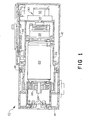
- the preferred embodiment of the present invention as incorporated in a servo motor drive module 10 for a robot joint is illustrated in Figure 1.
- the module comprises a two-section housing which encloses a servo drive motor, a gear reducer, a brake and the position encoder of the invention.
- a circuit board holding a microprocessor and other circuitry required to operate the servo motor in response to commands received from the central controller is also mounted within the housing.
- a microprocessor is incorporated for receiving and transmitting signals to the computer controller, and for performing the computations required to carry out the position sensing and motor drive functions involved in responding to the signals from the computer controller.
- controller refers to whatever control apparatus is appropriate to the chosen configuration, whether it is a relatively large mainframe computer or a more specialized computer control system developed for a particular robot system.
- Module 10 comprises a fixed housing 12 which is mounted on the input side of the robot joint and a movable housing 14 to which is attached the output side of the robot joint.
- Housing 14 is connected to housing 12 through bearings 16 and 18, so that the two housings can rotate freely with respect to each other.
- a mounting sleeve 22 is mounted within module 10, and fixedly connected to housing 12 by a mounting sleeve 22. Any suitable servo motor, for example, a Pittman model 13203 motor, may be used.
- One end of motor drive shaft 24 is connected to movable housing 14 through a gear reducer 26.
- a harmonic gear reducer for example the HDC-3C model made by Emhart, is well suited for robotics because it is compact, provides a relatively high ratio speed reduction, e.g., 120:1, and produces smooth operation and sufficient torque for moving the robot joint.
- the other end of shaft 24 is connected to brake 28 and to position encoder 30.
- Position encoder 30 comprises an incremental position encoder 32 and a discrete position encoder 34, both driven by the rotation of shaft 2 4 .
- Incremental encoder 32 is a rotating disc optical encoder of the type described in U.S. patent 4,266, 125 , for example.
- Encoder 32 produces two types of output signals: a series of pulses which indicate the relative incremental rotation of the shaft, and an index pulse once each revolution when the shaft rotates past an index position.
- the incremental encoder 32 has two output channels which produce 1000 pulses per revolution with the pulses of one channel shifted 90 degrees from those of the second channel. After decoding, these outputs can divide each shaft rotation into 4000 incremental segments and
- Discrete encoder 34 produces index pulses from each of two gears which precess with respect to the rotation of the motor drive shaft, as described in more detail below. From the pattern of index pulses produced by discrete encoder 34, the position of the joint can be determined to within one revolution of the drive shaft, as described below.
- circuit board 38 which i holds a microprocessor, a motor driver, logic to decode signals I from the incremental encoder, and other circuitry associated with the operation of the servo control module.
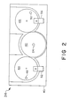
- Encoder 34 comprises a housing 40 holding three gears 42, 44 and 46.
- Gear 42 the center gear, has Tl teeth and is connected to motor drive shaft 24 for rotation with that shaft.
- Gear 42 drives first idler gear 4 4 having T2 teeth and second idler gear 46 having T3 teeth.
- Idler gears 44 and 46 have apertures 48 and 50 near their periphery.
- Also mounted on housing 40 are photodetectors 52 and 54, positioned over the periphery of gears 44 and 46 along the path of apertures 48 and 50 so that they can detect the passage of apertures 48 and 50 on each revolution of gears 44 and 46.
- the three gears 42, 44 and 46 have different numbers of teeth so that their rotations precess with respect to one another.
- One combination of tooth numbers which has been found to be particularly advantageous is 17, 16 and 15 teeth for gears 42, 44 and 46 respectively. Using this combination, for every revolution of gear 4 2 , gear 44 rotates 17/16 of a revolution and gear 46 rotates 17/15 of a revolution.
- gears 42 and 44 will not again be in alignment until after 16 revolutions of gear 42
- gears 42 and 46 will not again be in alignment until after 15 revolutions of gear 42
- all three gears will not again be in alignment until after 240 revolutions (15 x 16) of gear 42.
- the motor shaft at the index pulse for each of the 240 revolutions of the drive gear, hence the motor shaft, there is a unique combination of angular positions of apertures 48 and 50 with respect to photodetectors 52 and 54. If the motor is connected to the joint actuator output through a 120:1 gear reduction, this! provides a method of uniquely determining at which motor revolution the joint is positioned over 240 motor revolutions or two complete rotations of the joint.
- Another way to determine the range produced by a set of gears is to consider the number of "logical teerh" in each meshing pair of gears.
- the number of a gear's logical teeth is the number of physical teeth divided by the common factors between the numbers of physical teeth for that gear and for the gear with which it meshes.
- the 30 tooth idler has 15 logical teeth (30/2) and the 32 tooth idler has 16 logical teeth (32/2).
- Figure 3 shows a schematic block diagram of a servo control actuator system including the position encoding apparatus of the present invention.
- the output shaft of motor 20 is physically connected through gear reducer 26 to movable robot arm 36.
- the output shaft of motor 20 is also physically connected to brake 28, to incremental encoder 32 and to discrete encoder 34.
- the electrical signals produced by incremental encoder 32 and discrete encoder 34 are sent to circuit board 38 (indicated by dashed line).
- the signals from the incremental encoder go to decoder logic 56 which determines which direction shaft 24 is rotating and also processes the signals to produce an output signal suitable for digital counting.
- the output of decoder logic 56 goes to state counter 58 which accumulates the digital counts to keep track of the state of the incremental encoder and outputs the result to microprocessor 60.
- microprocessor 60 receives commands from the central controller.
- the position command orders microprocessor 60 to move the robot joint to a certain position.
- the initialize command orders microprocessor 60 to determine the position of the robot joint.
- microprocessor 60 transmits control signals to motor 2 0 through driver 62, and to brake 2 8 .
- the intialization command can be carried out with a minimum range of motion by the robot joint.
- the absolute position of the joint can be determined. This minimizes the time required for initialization and also minimizes the chance that the robot arm will hit an obstruction during the initialization procedure.
- microprocessor 6 0 Upon receiving the initialization command, microprocessor 6 0 directs motor 20 to rotate in a counterclockwise direction. The rotation is stopped a predetermined portion of a motor revolution past the first index pulse which microprocessor 60 receives from incremental encoder 32. Travel past the index position is desirable to remove any effect of gear backlash in the encoder from the position measurement. This procedure also simplifies the construction of the encoder by obviating the need for any mechanical means for eliminating backlash.
- Microprocessor 60 then directs the motor to rotate in the clockwise direction. As the motor shaft rotates, microprocessor 60 records the position of the index pulse from encoder 32 and counts the number of incremental pulses between the index pulse i and the position pulses (called "marks") received from photodetectors 52 and 54 of discrete encoder 34. When the microprocessor receives a second index pulse from incremental encoder 32, the motor is stopped. Because the drive gear 42 has a larger number of teeth than the two idler gears 44 and 46, it is assured that mark pulses from both photodetectors will occur between any two index pulses from incremental encoder 32.
- the number of incremental pulses between the index pulse and each of the mark pulses represents an angular difference in position between the drive gear and the respective idler gears.
- Each motor revolution in the range of 240 revolutions is represented by a unique combination of such angular differences.
- idler gear 44 after one revolution from the "zero" position, idler gear 44 will be one tooth ahead of the drive gear and idler gear 46 will be two teeth ahead.
- idler gear 44 After n revolution from zero, idler gear 44 will be n teeth ahead or n modulo 16 teeth apart from the index pulse.
- idler gear 46 will be 2n teeth ahead or 2n modulo 15 teeth apart from the index pulse. Since the microprocessor measures the angular separation directly, the motor revolution represented by the combination can be calculated or alternatively determined by comparing the measured values with predetermined values stored in a table in the memory of the microprocessor.
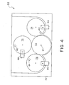
- FIG. 4 shows an alternate embodiment of the discrete encoder of the invention.
- Encoder 63 comprises a housing 70 which holds the drive gear 72 and the three idler gears 74, 76 and 78.
- drive gear 72 is connected to motor drive shaft 24 and drives the three idler gears.
- Idler gears 74 , 76 and 78 have apertures 80, 82 and 84 near their periphery.
- photodetectors 86, 8 8 and 90 mounted on housing 70, positioned over each of the idler gears along the path of apertures 80, 82 and 84 so that they can detect the passage of the apertures on each revolution of idler gears 74, 76 and 78.
- each of the gears have different numbers of teeth so that their rotations precess with respect to one another.
- drive gear 72 has Tl teeth
- idler gear 74 has T2 teeth
- gear 76 has T3 teeth
- gear 78 has T4 teeth
- the four gear set provides a unique combination of angular positions of the three idler gears with respect to the drive gear for T2 x T3 x T4 motor revolutions, provided that Tl, T2, T3 and T4 have no common factors.
- the additional gear multiplies the range of motor revolutions which can be resolved by a factor equal to the number of logical teeth on the added gear. It can be seen that by adding more idler gears, the range of motor revolutions which an encoder can resolve can be expanded to suit the needs of the designer.
- the encoder can be built with only one idler gear if the number of logical teeth on that gear provides a sufficient range.
- two or more discrete encoders may be stacked together with their outputs concatenated to further expand the range which can be resolved.
- Other methods may be used to link the encoder to the actuator, for instance components of harmonic gear reducer 26 could be used to drive the discrete encoder.
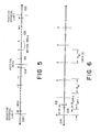
- FIG. 5 is a graphic representation of the motor position space, showing the location of index pulses produced by the incremental encoder within that space.
- the physical zero position 101 of the robot joint whose motion is represented in Figure 5 is the middle of the motor position space, with the positive physical limit 102 and the negative physical limit 103 at either end, establishing the physical range of motion of the joint.
- the index zero position 10 4 indicated as 0, generally is not coincident with the physical zero position 101 due to the arbitrary position of the disc of the incremental encoder when the servo drive module is assembled with the robot arm.
- the index pulse used as index zero 104 is chosen so that physical zero 101 falls within the first positive motor revolution. From index zero 104, the motor space is divided by index pulses from incremental encoder 32 into a series of motor revolution segments 105 extending clockwise to the positive physical limit 102 and counterclockwise to the negative physical limit 103. For a motor space which extends n revolutions in the positive and negative direction, the gears of the discrete encoder should be chosen to provide a range greater than 2n.
- Figure 6 shows a section of the motor space in more detail, including the mark pulses from one gear of the discrete encoder.
- the mark pulses from the second gear are omitted for clarity, and ! the following discussion applies equally to the index pulses from each gear.
- the physical zero 101 and index zero 104 are not coincident.
- the separation is designated ⁇ z, the zero offset.
- Figure 6 shows that the zero index pulse is not coincident with a discrete encoder mark pulse 106.
- This separation is designated in two parts, Toffl which is an integral number of teeth and ⁇ offl which is the fractional remainder.
- the fractional part ⁇ offl is used as a calibration constant so that the position calculations can be done using the angular displacement of an integral tooth as the smallest division.
- microprocessor 60 To locate the position of the robot joint within the motor space, microprocessor 60 first determines the angular displacement between the index pulse and the mark pulses. Then microprocessor 60 determines which motor revolution is associated with that combination of angular differences.
- the angular displacement is determined by finding the next index pulse in the counterclockwise direction, then moving through one motor revolution and finding the two mark pulses.
- At the index pulse and at each mark pulse i microprocessor 60 stores the output of incremental encoder state counter 58.
- the angular displacement of the first idler gear mark in incremental encoder counts is the difference between the stored values at the index pulse and the stored value at the first idler mark pulse.
- the result is adjusted by subtracting offset value ⁇ offl, then expressed as a number of teeth by dividing by the number of incremental encoder counts per logical tooth and rounding to the nearest integral number.
- a similar procedure is followed to determine the angular displacement of the second idler gear.
- the motor revolution associated with the two angular displacements remains to be determined. As described above, this can be accomplished by comparing the measured displacement values with the values stored in a table in memory until a match is found. Alternatively, the table of values can be generated and compared with the measured displacement values.
- the absolute position of the robot joint can then be expressed in incremental encoder counts as:
Applications Claiming Priority (2)
| Application Number | Priority Date | Filing Date | Title |
|---|---|---|---|
| US73254985A | 1985-05-10 | 1985-05-10 | |
| US732549 | 1985-05-10 |
Publications (2)
| Publication Number | Publication Date |
|---|---|
| EP0201106A2 true EP0201106A2 (fr) | 1986-11-12 |
| EP0201106A3 EP0201106A3 (fr) | 1990-01-17 |
Family
ID=24943968
Family Applications (1)
| Application Number | Title | Priority Date | Filing Date |
|---|---|---|---|
| EP86106353A Withdrawn EP0201106A3 (fr) | 1985-05-10 | 1986-05-09 | Codeur absolu de position |
Country Status (2)
| Country | Link |
|---|---|
| EP (1) | EP0201106A3 (fr) |
| JP (1) | JPS61258113A (fr) |
Cited By (8)
| Publication number | Priority date | Publication date | Assignee | Title |
|---|---|---|---|---|
| EP0286322A2 (fr) * | 1987-04-03 | 1988-10-12 | Hitachi, Ltd. | Méthode et appareil de détection d'angle de rotation |
| DE3720828A1 (de) * | 1987-06-24 | 1989-01-05 | Bosch Gmbh Robert | Messeinrichtung und verfahren zur lageistwerterfassung |
| EP0331828A1 (fr) * | 1986-09-29 | 1989-09-13 | Kabushiki Kaisha Yaskawa Denki Seisakusho | Codeur absolu de type multirotationnel |
| DE3837526A1 (de) * | 1988-09-23 | 1989-12-28 | Kuka Schweissanlagen & Roboter | Verfahren und vorrichtung zum justieren einer achse |
| WO1991006152A1 (fr) * | 1989-10-16 | 1991-05-02 | Nauchno-Proizvodstvennoe Obiedinenie 'granat' | Procede de conversion de la position angulaire d'un arbre en un code |
| EP0714171A3 (fr) * | 1994-11-23 | 1998-01-07 | Dr. Johannes Heidenhain GmbH | Dispositif et procédé pour la détermination de la position d'un corps |
| WO2015128087A1 (fr) * | 2014-02-28 | 2015-09-03 | gomtec GmbH | Transmetteur d'angle de rotation |
| US9310195B2 (en) | 2010-08-24 | 2016-04-12 | Rotork Controls Limited | Apparatus adapted to provide an indication of an angular position of an input member over multiple turns |
Families Citing this family (3)
| Publication number | Priority date | Publication date | Assignee | Title |
|---|---|---|---|---|
| KR100610384B1 (ko) | 2004-10-06 | 2006-08-10 | 현대모비스 주식회사 | 절대조향각 및 토크 측정 방법과 측정 장치. |
| JP4992516B2 (ja) * | 2007-04-02 | 2012-08-08 | パナソニック株式会社 | 回転角度検出装置 |
| JP5420624B2 (ja) * | 2011-11-14 | 2014-02-19 | オリエンタルモーター株式会社 | 多回転アブソリュート回転角検出装置及びアブソリュート回転角を検出する方法 |
Citations (3)
| Publication number | Priority date | Publication date | Assignee | Title |
|---|---|---|---|---|
| FR2335823A1 (fr) * | 1975-12-18 | 1977-07-15 | Otis Elevator Co | Systemes transmetteurs de position d'arbre a grande resolution et a large gamme |
| FR2389101A1 (fr) * | 1977-04-25 | 1978-11-24 | Schlatter Ag | Codeur de rotation |
| US4398110A (en) * | 1982-05-05 | 1983-08-09 | Westinghouse Electric Corp. | Harmonic electric actuator |
-
1986
- 1986-05-09 JP JP61106536A patent/JPS61258113A/ja active Pending
- 1986-05-09 EP EP86106353A patent/EP0201106A3/fr not_active Withdrawn
Patent Citations (3)
| Publication number | Priority date | Publication date | Assignee | Title |
|---|---|---|---|---|
| FR2335823A1 (fr) * | 1975-12-18 | 1977-07-15 | Otis Elevator Co | Systemes transmetteurs de position d'arbre a grande resolution et a large gamme |
| FR2389101A1 (fr) * | 1977-04-25 | 1978-11-24 | Schlatter Ag | Codeur de rotation |
| US4398110A (en) * | 1982-05-05 | 1983-08-09 | Westinghouse Electric Corp. | Harmonic electric actuator |
Cited By (18)
| Publication number | Priority date | Publication date | Assignee | Title |
|---|---|---|---|---|
| EP0464870A2 (fr) * | 1986-09-29 | 1992-01-08 | Kabushiki Kaisha Yaskawa Denki Seisakusho | Codeur absolu de type multirotationnel |
| EP0463643A3 (en) * | 1986-09-29 | 1992-05-13 | Kabushiki Kaisha Yaskawa Denki Seisakusho | Absolute encoder of the multirotation type |
| EP0331828A1 (fr) * | 1986-09-29 | 1989-09-13 | Kabushiki Kaisha Yaskawa Denki Seisakusho | Codeur absolu de type multirotationnel |
| EP0466209A3 (en) * | 1986-09-29 | 1992-05-13 | Kabushiki Kaisha Yaskawa Denki Seisakusho | Absolute encoder of the multirotation type |
| EP0464870A3 (en) * | 1986-09-29 | 1992-05-13 | Kabushiki Kaisha Yaskawa Denki Seisakusho | Absolute encoder of the multirotation type |
| EP0466209A2 (fr) * | 1986-09-29 | 1992-01-15 | Kabushiki Kaisha Yaskawa Denki Seisakusho | Codeur absolu de type multirotationnel |
| EP0463643A2 (fr) * | 1986-09-29 | 1992-01-02 | Kabushiki Kaisha Yaskawa Denki Seisakusho | Codeur absolu de type multirotationnel |
| EP0286322A3 (en) * | 1987-04-03 | 1990-12-27 | Hitachi, Ltd. | Method and apparatus for detecting a rotation angle |
| EP0286322A2 (fr) * | 1987-04-03 | 1988-10-12 | Hitachi, Ltd. | Méthode et appareil de détection d'angle de rotation |
| DE3720828A1 (de) * | 1987-06-24 | 1989-01-05 | Bosch Gmbh Robert | Messeinrichtung und verfahren zur lageistwerterfassung |
| DE3837526A1 (de) * | 1988-09-23 | 1989-12-28 | Kuka Schweissanlagen & Roboter | Verfahren und vorrichtung zum justieren einer achse |
| WO1991006152A1 (fr) * | 1989-10-16 | 1991-05-02 | Nauchno-Proizvodstvennoe Obiedinenie 'granat' | Procede de conversion de la position angulaire d'un arbre en un code |
| EP0714171A3 (fr) * | 1994-11-23 | 1998-01-07 | Dr. Johannes Heidenhain GmbH | Dispositif et procédé pour la détermination de la position d'un corps |
| US9310195B2 (en) | 2010-08-24 | 2016-04-12 | Rotork Controls Limited | Apparatus adapted to provide an indication of an angular position of an input member over multiple turns |
| WO2015128087A1 (fr) * | 2014-02-28 | 2015-09-03 | gomtec GmbH | Transmetteur d'angle de rotation |
| CN106062519A (zh) * | 2014-02-28 | 2016-10-26 | Abb高姆技术有限责任公司 | 旋转编码器 |
| CN106062519B (zh) * | 2014-02-28 | 2018-10-19 | Abb高姆技术有限责任公司 | 旋转编码器 |
| US11193799B2 (en) | 2014-02-28 | 2021-12-07 | Abb Schweiz Ag | Rotary encoder for determining the angular position between two rotating components |
Also Published As
| Publication number | Publication date |
|---|---|
| EP0201106A3 (fr) | 1990-01-17 |
| JPS61258113A (ja) | 1986-11-15 |
Similar Documents
| Publication | Publication Date | Title |
|---|---|---|
| US5457371A (en) | Binary locally-initializing incremental encoder | |
| JP3143310B2 (ja) | 位置検出装置、補正機能付位置検出装置、位置検出方法、および、位置検出装置の補正方法 | |
| EP0201106A2 (fr) | Codeur absolu de position | |
| NO842324L (no) | Automatisk, dynamisk feilkompensator | |
| US6914543B2 (en) | Method for initializing position with an encoder | |
| US4857816A (en) | Precise positioning apparatus | |
| EP0666520B1 (fr) | Procédé et dispositif de détection de la position | |
| EP2474902B1 (fr) | Appareil de traitement de signal pour codeurs | |
| US4599601A (en) | Absolute incremental encoder | |
| US6356219B1 (en) | Calibrated encoder multiplier | |
| US4841297A (en) | Displacement coder | |
| US5093610A (en) | Apparatus for absolute position measurement | |
| IE851579L (en) | Detecting step losses in stepping motors | |
| KR101843421B1 (ko) | 스마트 액추에이터 모듈 및 그 구동 제어 방법 | |
| WO1989010237A1 (fr) | Appareil servant a suivre la surface d'une piece a usiner | |
| EP0474362B1 (fr) | Appareil pour détecter la vitesse angulaire | |
| JP2727542B2 (ja) | アーム位置検出方法 | |
| JPH0515963B2 (fr) | ||
| US5191271A (en) | Process and device for adjusting an axis | |
| JPS62225908A (ja) | 位置検出装置 | |
| CN108534803B (zh) | 混合式编码器的码盘及其设计方法 | |
| JP2570039B2 (ja) | 移動位置校正装置 | |
| KR100245042B1 (ko) | 수치제어시스템 | |
| Coiffet et al. | Internal sensors | |
| JPS63289416A (ja) | パルス・エンコ−ダ |
Legal Events
| Date | Code | Title | Description |
|---|---|---|---|
| PUAI | Public reference made under article 153(3) epc to a published international application that has entered the european phase |
Free format text: ORIGINAL CODE: 0009012 |
|
| AK | Designated contracting states |
Kind code of ref document: A2 Designated state(s): DE FR GB |
|
| PUAL | Search report despatched |
Free format text: ORIGINAL CODE: 0009013 |
|
| AK | Designated contracting states |
Kind code of ref document: A3 Designated state(s): DE FR GB |
|
| 17P | Request for examination filed |
Effective date: 19900118 |
|
| 17Q | First examination report despatched |
Effective date: 19900713 |
|
| STAA | Information on the status of an ep patent application or granted ep patent |
Free format text: STATUS: THE APPLICATION IS DEEMED TO BE WITHDRAWN |
|
| 18D | Application deemed to be withdrawn |
Effective date: 19920623 |
|
| RIN1 | Information on inventor provided before grant (corrected) |
Inventor name: GORDON, GARY Inventor name: KEITH, WILLIAMSON Inventor name: ANDREWS, RANDY |