EP0200835B1 - Festverankerte Teilprothese für Zähne - Google Patents
Festverankerte Teilprothese für Zähne Download PDFInfo
- Publication number
- EP0200835B1 EP0200835B1 EP85309002A EP85309002A EP0200835B1 EP 0200835 B1 EP0200835 B1 EP 0200835B1 EP 85309002 A EP85309002 A EP 85309002A EP 85309002 A EP85309002 A EP 85309002A EP 0200835 B1 EP0200835 B1 EP 0200835B1
- Authority
- EP
- European Patent Office
- Prior art keywords
- pontic
- male
- denture
- glass
- visible light
- Prior art date
- Legal status (The legal status is an assumption and is not a legal conclusion. Google has not performed a legal analysis and makes no representation as to the accuracy of the status listed.)
- Expired - Lifetime
Links
- 238000005304 joining Methods 0.000 claims abstract description 14
- 230000005855 radiation Effects 0.000 claims abstract description 11
- 239000006112 glass ceramic composition Substances 0.000 claims abstract description 9
- 239000000463 material Substances 0.000 claims description 14
- 239000002241 glass-ceramic Substances 0.000 claims description 13
- 239000000919 ceramic Substances 0.000 claims description 10
- 239000000203 mixture Substances 0.000 claims description 8
- 239000011521 glass Substances 0.000 claims description 7
- 239000000805 composite resin Substances 0.000 claims description 5
- 230000005540 biological transmission Effects 0.000 claims description 3
- 239000004568 cement Substances 0.000 claims description 3
- 229920000554 ionomer Polymers 0.000 claims description 2
- 229920005646 polycarboxylate Polymers 0.000 claims description 2
- LRXTYHSAJDENHV-UHFFFAOYSA-H zinc phosphate Chemical class [Zn+2].[Zn+2].[Zn+2].[O-]P([O-])([O-])=O.[O-]P([O-])([O-])=O LRXTYHSAJDENHV-UHFFFAOYSA-H 0.000 claims description 2
- 229910052751 metal Inorganic materials 0.000 description 8
- 239000002184 metal Substances 0.000 description 8
- 230000033001 locomotion Effects 0.000 description 7
- 239000011347 resin Substances 0.000 description 7
- 229920005989 resin Polymers 0.000 description 7
- 238000004519 manufacturing process Methods 0.000 description 5
- 238000010438 heat treatment Methods 0.000 description 4
- 229910052573 porcelain Inorganic materials 0.000 description 4
- 238000010276 construction Methods 0.000 description 3
- 230000006872 improvement Effects 0.000 description 3
- 238000000034 method Methods 0.000 description 3
- 238000007789 sealing Methods 0.000 description 3
- KRHYYFGTRYWZRS-UHFFFAOYSA-M Fluoride anion Chemical compound [F-] KRHYYFGTRYWZRS-UHFFFAOYSA-M 0.000 description 2
- MCMNRKCIXSYSNV-UHFFFAOYSA-N Zirconium dioxide Chemical compound O=[Zr]=O MCMNRKCIXSYSNV-UHFFFAOYSA-N 0.000 description 2
- 238000004873 anchoring Methods 0.000 description 2
- 230000001815 facial effect Effects 0.000 description 2
- 238000011065 in-situ storage Methods 0.000 description 2
- 230000004048 modification Effects 0.000 description 2
- 238000012986 modification Methods 0.000 description 2
- ZKATWMILCYLAPD-UHFFFAOYSA-N niobium pentoxide Chemical compound O=[Nb](=O)O[Nb](=O)=O ZKATWMILCYLAPD-UHFFFAOYSA-N 0.000 description 2
- 239000004033 plastic Substances 0.000 description 2
- 229920003023 plastic Polymers 0.000 description 2
- BASFCYQUMIYNBI-UHFFFAOYSA-N platinum Chemical compound [Pt] BASFCYQUMIYNBI-UHFFFAOYSA-N 0.000 description 2
- 206010073306 Exposure to radiation Diseases 0.000 description 1
- 229910007676 ZnO—SiO2 Inorganic materials 0.000 description 1
- SXMUXFDPJBTNRM-UHFFFAOYSA-N [2-hydroxy-3-[4-[2-[4-[2-hydroxy-3-(2-methylprop-2-enoyloxy)propoxy]phenyl]propan-2-yl]phenoxy]propyl] 2-methylprop-2-enoate;2-[2-[2-(2-methylprop-2-enoyloxy)ethoxy]ethoxy]ethyl 2-methylprop-2-enoate Chemical compound CC(=C)C(=O)OCCOCCOCCOC(=O)C(C)=C.C1=CC(OCC(O)COC(=O)C(=C)C)=CC=C1C(C)(C)C1=CC=C(OCC(O)COC(=O)C(C)=C)C=C1 SXMUXFDPJBTNRM-UHFFFAOYSA-N 0.000 description 1
- 239000006096 absorbing agent Substances 0.000 description 1
- NIXOWILDQLNWCW-UHFFFAOYSA-N acrylic acid group Chemical group C(C=C)(=O)O NIXOWILDQLNWCW-UHFFFAOYSA-N 0.000 description 1
- 230000004075 alteration Effects 0.000 description 1
- PNEYBMLMFCGWSK-UHFFFAOYSA-N aluminium oxide Inorganic materials [O-2].[O-2].[O-2].[Al+3].[Al+3] PNEYBMLMFCGWSK-UHFFFAOYSA-N 0.000 description 1
- 239000006105 batch ingredient Substances 0.000 description 1
- 230000015572 biosynthetic process Effects 0.000 description 1
- 238000005266 casting Methods 0.000 description 1
- 150000001768 cations Chemical class 0.000 description 1
- 229910010293 ceramic material Inorganic materials 0.000 description 1
- 229910052681 coesite Inorganic materials 0.000 description 1
- 238000001816 cooling Methods 0.000 description 1
- 238000012937 correction Methods 0.000 description 1
- 229910052593 corundum Inorganic materials 0.000 description 1
- 229910052906 cristobalite Inorganic materials 0.000 description 1
- 239000013078 crystal Substances 0.000 description 1
- 239000003479 dental cement Substances 0.000 description 1
- 239000011351 dental ceramic Substances 0.000 description 1
- 210000003298 dental enamel Anatomy 0.000 description 1
- 239000002670 dental porcelain Substances 0.000 description 1
- 230000001747 exhibiting effect Effects 0.000 description 1
- 239000000835 fiber Substances 0.000 description 1
- 239000000156 glass melt Substances 0.000 description 1
- PCHJSUWPFVWCPO-UHFFFAOYSA-N gold Chemical compound [Au] PCHJSUWPFVWCPO-UHFFFAOYSA-N 0.000 description 1
- 239000010931 gold Substances 0.000 description 1
- 229910052737 gold Inorganic materials 0.000 description 1
- 239000004615 ingredient Substances 0.000 description 1
- 238000011005 laboratory method Methods 0.000 description 1
- 229910001635 magnesium fluoride Inorganic materials 0.000 description 1
- 230000007246 mechanism Effects 0.000 description 1
- 239000000155 melt Substances 0.000 description 1
- 239000007769 metal material Substances 0.000 description 1
- 229910001463 metal phosphate Inorganic materials 0.000 description 1
- 150000002739 metals Chemical class 0.000 description 1
- 230000000704 physical effect Effects 0.000 description 1
- 229910052697 platinum Inorganic materials 0.000 description 1
- 238000006116 polymerization reaction Methods 0.000 description 1
- 239000006064 precursor glass Substances 0.000 description 1
- 238000009877 rendering Methods 0.000 description 1
- 230000000717 retained effect Effects 0.000 description 1
- 239000000377 silicon dioxide Substances 0.000 description 1
- VYPSYNLAJGMNEJ-UHFFFAOYSA-N silicon dioxide Inorganic materials O=[Si]=O VYPSYNLAJGMNEJ-UHFFFAOYSA-N 0.000 description 1
- 229910052709 silver Inorganic materials 0.000 description 1
- 239000004332 silver Substances 0.000 description 1
- 229910000679 solder Inorganic materials 0.000 description 1
- 229910052596 spinel Inorganic materials 0.000 description 1
- 239000011029 spinel Substances 0.000 description 1
- 238000010186 staining Methods 0.000 description 1
- 229910052682 stishovite Inorganic materials 0.000 description 1
- 239000000126 substance Substances 0.000 description 1
- 229910052905 tridymite Inorganic materials 0.000 description 1
- 229910001845 yogo sapphire Inorganic materials 0.000 description 1
Images
Classifications
-
- A—HUMAN NECESSITIES
- A61—MEDICAL OR VETERINARY SCIENCE; HYGIENE
- A61C—DENTISTRY; APPARATUS OR METHODS FOR ORAL OR DENTAL HYGIENE
- A61C13/00—Dental prostheses; Making same
- A61C13/0003—Making bridge-work, inlays, implants or the like
- A61C13/0006—Production methods
-
- A—HUMAN NECESSITIES
- A61—MEDICAL OR VETERINARY SCIENCE; HYGIENE
- A61C—DENTISTRY; APPARATUS OR METHODS FOR ORAL OR DENTAL HYGIENE
- A61C13/00—Dental prostheses; Making same
- A61C13/225—Fastening prostheses in the mouth
-
- A—HUMAN NECESSITIES
- A61—MEDICAL OR VETERINARY SCIENCE; HYGIENE
- A61C—DENTISTRY; APPARATUS OR METHODS FOR ORAL OR DENTAL HYGIENE
- A61C13/00—Dental prostheses; Making same
- A61C13/225—Fastening prostheses in the mouth
- A61C13/26—Dentures without palates; Partial dentures, e.g. bridges
Definitions
- This invention relates to the fabrication of fixed partial dentures (bridges) to replace missing teeth in the anterior and posterior areas of the mouth.
- fixed partial dentures have comprised at least three parts, viz., two abutment crowns and a pontic therebetween.
- a bridge In fabricating a bridge, an impression is made of the area in the patient's mouth, a cast is prepared, and a dental technician then fashions a bridge therefrom.
- metal materials are employed, the three parts may be formed as an integral unit or the parts soldered or otherwise joined into a single unit.
- ceramic materials are involved, the components are typically assembled at the dental laboratory and delivered to the dentist as a single unit.
- a low temperature fusing solder glass (a dental porcelain) or other sealing means is used to surround the other aluminous porcelain or other ceramic components.
- the customary mode of attachment has involved simple butt sealing or, occasionally, sealing by means of a dovetail or tongue-and-groove configuration.
- Such forms of attachment do not permit adjustments in the overall geometry of a appliance or in the profile of the individual parts to be quickly and readily performed. Accordingly, when the dentist notes inaccuracies in the fitting to the abutment teeth in the patient's mouth, the common practice is to return the bridge to the dental technician for the necessary alterations. Not infrequently, the metal appliance frame must be separated, the required adjustments made, and the parts re-soldered. As can be appreciated, those circumstances demand at least one further visit by the patient to the dentist's office to insure proper fitting.
- US-A-2,129,861 describes the fabrication of a metal bridge comprising a rigid attachment at one end thereof to an anchoring tooth and a movable ball and socket attachment at the other end of the bridge to the other anchoring tooth.
- the connecting means consisted of a separate metal lock pin composed of a shank portion with a ball on one end thereof, the ball being movably embedded in an anchor tooth.
- the final bridge is not composed of units fixedly bonded to each other.
- US-A-2,808,648 is directed to the fabrication of spring clamp joints for releasibly securing partial dental prostheses to a pillar tooth.
- the connecting means comprises a separate spring clamp device, such that the prosthesis does not consist of units fixedly bonded together.
- US-A-3,530,582 refers to U.S. Patent US-A-2,129,861 above; the improvement thereupon residing in the use of a lock pin having a ball on each end of the pin instead of only on one end, each ball being movably embedded in an anchor tooth.
- US-A-4,472,142 discloses the fabrication of a removable partial denture utilizing an attachment means involving a cylindrical pin having one end attached to the proximal surface of a crown and the other end removably retained in a hollow tubular member.
- the hollow tubular member is frictionally and rotatably mounted at one end in the bottom of the base of the denture which holds the artificial tooth adjacent the abutment tooth.
- the other end thereof has an axial slot in the wall of sufficient length and width to enable the pin to be inserted into the tubular member with slight flexure of the walls of the slot. The slot walls thus hold the pin within the member.
- DE-C-660344 describes a fixed partial denture consisting of abutment crowns and at least one pontic fixedly connected through at least one male/female connector to form a unitary structure, the female portion or portions of the connector being located within the pontic or pontics and/or within the abutment crowns of said denture, and the male portion or portions of the connector having a length extending up to or beyond the entire mesial-distal length of the pontic or pontics, said crowns and pontic or pontics being fixedly joined together by means of a joining medium.
- the male connectors are in the form of flexible wires soldered to gold crowns.
- the female portions which receive the wires are provided by a ceramic tube located within a porcelain pontic section.
- a denture of the type described in DE-C-660344 characterised in that the or each male portion is in the form of a rigid male connector formed integrally with the respective abutment crown of a ceramic or glass-ceramic material, and the or each female portion being in the form of a cavity therefor.
- the fixed partial denture of the present invention permits adjustments to be made quickly and readily, thereby insuring proper fitting of the bridge in a single visit by the patient to the dentist's office.
- the male connector will extend through and beyond the pontic. In other designs, the length thereof will not exceed about 75% and, most preferably, not exceed about 50% of the mesial-distal length of the pontic.
- the female portion(s) of the attachment(s) is typically, but not necessarily, located solely within the pontic.
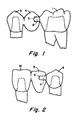
- FIGURE 1 is a schematic representation of a two-part, fixed partial denture comprising one illustrative embodiment of the present invention.
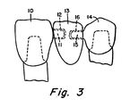
- FIGURES 2 and 3 are schematic representations of three-part, fixed partial dentures comprising other illustrative embodiments of the present invention.
- FIGURE 1 schematically represents a two-piece prosthesis. As is pictured there, 1 indicates an abutment crown having male connector 2 integral therewith and extending into cavity 3 of pontic 4, cavity 3 comprising the female portion of the attachment. In this embodiment, pontic 4 is integral with abutment crown 5.
- FIGURE 2 schematically depicts a three-piece apppliance.
- 6 represents an abutment crown having male connector 7 unitary therewith and extending into female portion of the attachment 8 of pontic 9.
- Pontic 9 is a separate part which is cemented to abutment crown 10.
- FIGURE 3 schematically illustrates another three-piece bridge.
- 10 represents an abutment crown having male connector 11 integral therewith and extending into cavity 12 of pontic 13.
- 14 indicates another abutment crown which has male connector 15 unitary therewith and extending into cavity 16 of pontic 13.
- FIGURE 3 illustrates the use of double attachment through two male connectors in two female portions of the pontic.
- the male connector and the corresponding female portion will have a substantially cylindrical outline, although an oval or other curved geometry can be operable.
- a cylindrical configuration permits unlimited rotation of the parts, whereas an oval or other non-circular profile partially restrains rotary movement.
- Sharp corners, such as are present in a square or triangular outline, are not as desirable since rotation of the parts is inhibited.
- inventive male/female attachment means also permits lateral movement of the parts prior to their being fixedly bonded into a unitary structure. This feature provides another degree of freedom in adjusting the bridge to fit into a patient's mouth. For example, that movement can compensate for any drift of a patient's teeth between the time the impression was made to prepare the bridge and the time of fitting the appliance into the patient's mouth.
- the inventive method is operable in fabricating prostheses from any of the many materials that are currently employed in the fabrication thereof, with the proviso that the or each male connector and the abutment crown with which it is integral are of a ceramic or glass-ceramic material.
- the inventive method is especially suitable for use in bridges prepared from glass-ceramic materials. Because glass-ceramics are prepared through the heat treatment of precursor glass bodies, the ready formability of glass melts is advantageous in obtaining, as for example by casting, the desired complex shapes of abutment crowns with male connectors integral therewith and pontics having cavities therein. Hence, all parts of the denture can be composed of the same glass-ceramic composition.
- the male portions of the inventive bridges and the abutment crowns with which they are integral may be composed of a ceramic or glass-ceramic material, and the remainder thereof of metal, plastic, fiber reinforced glass, or another ceramic or glass-ceramic.
- U.S-A- 4,189,325 described the use of glass-ceramics in dental restorations having base compositions within the Li2O-CaO-Al2O3-SiO2 system nucleated with platinum and Nb2O5.
- U.S-a-4,431,420 disclosed machinable glass-ceramic materials, suitable for use in dental restorations, containing tetrasilicic fluormica as the predominant crystal phase and having base compositions within the K2O-MgO-SiO2-F system with Al2O3 and/or ZrO2 being optionally present. Because of their physical properties, their resistance to staining and chemical attack in an oral environment, and their close similarity in appearance to tooth enamel, dental crowns are currently being fabricated from those materials.
- compositions of those glass-ceramics consist essentially, expressed in terms of weight percent on the oxide basis, of: Glass bodies prepared from those compositions can be crystallized in situ to glass-ceramics by heat treatment at temperatures between about 1050°-1150°C.
- the use of joining media to bond together the parts of a bridge into a unitary structure is advantageous in achieving a customized fit in a patient's mouth.
- the appliance parts with the joining medium applied at the proper locations can be assembled outside of the patient's mouth, the assembly placed inside the patient's mouth, the parts moved to accommodate precisely to the contour of the mouth, and the medium cured in place.
- the use of joining media in fixed partial dentures is also advantageous from a second standpoint, that is, the elastic modulus of the medium may be considerably less than that of the appliance parts such that it can act as a stress absorber, i.e., it provides some "give".
- any of the conventional time-setting dental cements such as zinc phosphates, glass ionomers, polycarboxylates, etc.
- the most preferred joining media are composite resins which can be cured upon exposure to radiation, e.g., ultraviolet and/or visible light radiation.
- Such joining media are quite apparently useful only with materials which permit the transmission of those radiations therethrough.
- the machinable glass-ceramics of US-A- 4,431,420 discussed above are sufficiently translucent to allow the use of those cements.
- the prosthesis may simply be set in the mouth to achieve the proper fit, carefully removed therefrom, and the entire cure conducted outside the mouth. Because of a possible hazard to the patient through exposure to ultraviolet radiation, the most preferred joining media are composite resins which are cured under high intensity visible light.
- the most preferred materials from which the individual parts of the inventive dentures are fashioned are the glass-ceramics disclosed in US-A- 4,431,325. Also, the most preferred joining media are composite resins which are cured upon exposure to high intensity visible light radiation. With those two factors in mind, the invention will be described with specific reference to FIGURE 1.
- the melt was cast into two refractory investments, the cavities of which being designed to produce the proper geometries for parts 1 and 5 of the bridge depicted in FIGURE 1.
- the resultant glass shapes were subsequently crystallized in situ to glass-ceramics through heat treatment according to the following schedule: heating at a rate of about 200°C/hour to 1075°C, holding at that temperature for about six hours, and then cooling to room temperature, desirably at a rate of about 200°C/hour:
- the glass-ceramic parts were fitted to a die, apparent inaccuracies in the contour of the parts rectified, and surface tinting of the parts undertaken where desired, all according to standard dental laboratory techniques employed by laboratories using the commercially-available DICOR TM procedures licensed by Dentsply International, Inc., York, Pennsylvania.
- the ready machinability of the glass-ceramic enables corrections in surface contour to be made with relative ease.
- the parts were then assembled in a patient's mouth.
- a visible light curing resin will be inserted within the female attachment and/or applied onto the male connector, the male connector will be introduced into the female attachment, the so-assembled interconnected parts placed upon their respective abutment teeth, and then exposed to a high energy source of visible light for a period of time adequate to develop a sufficient depth of cure in the resin.
- the resin used was Prisma-Fil®, a visible light cure composite resin marketed by L. D. Caulk Company of Milford, Delaware. That resin was diluted slightly with Prisma-Bond®, an unfilled visible light cure resin also marketed by L. D. Caulk Company.
- the source of high intensity visible light was a Prisma-Lite® curing light, also marketed by L. D. Caulk Company, having an output of about 387-460 milliwatts/cm2 and exhibiting substantial intensity in the wavelength region of 400-500 nm.
- the high intensity light was directed for 20 seconds to each of the occlusal, facial, and lingual surfaces of the attachment to polymerize the resin and initiate sufficient cure to fix the interconnecting parts into an integral structure. Thereafter, the bridge was removed from the patient's mouth and the occlusal, facial, gingival, and lingual areas thereof re-exposed to the Prisma-Lite® for 20 seconds to insure complete polymerization of the resin to form a fixedly bonded unitary structure. The bridge was then replaced in the patient's mouth and cemented to the abutment teeth.
Landscapes
- Health & Medical Sciences (AREA)
- Oral & Maxillofacial Surgery (AREA)
- Veterinary Medicine (AREA)
- Epidemiology (AREA)
- Life Sciences & Earth Sciences (AREA)
- Animal Behavior & Ethology (AREA)
- General Health & Medical Sciences (AREA)
- Public Health (AREA)
- Dentistry (AREA)
- Engineering & Computer Science (AREA)
- Manufacturing & Machinery (AREA)
- Dental Prosthetics (AREA)
- Adhesives Or Adhesive Processes (AREA)
- Dental Preparations (AREA)
- Prostheses (AREA)
- Materials For Medical Uses (AREA)
Claims (8)
- Festverankerte Teilprothese für Zähne, bestehend aus angrenzenden Kronen (1,5; 6,10; 10,14) und mindestens einer Brücke, die fest durch mindestens ein Stecker/Buchsen-Verbindungsstück zur Bildung eines einheitlichen Aufbaus verbunden sind, wobei der bzw. die Buchsenabschnitte (3; 8; 12,16) des Verbindungsstücks, innerhalb der Brücke bzw. Brücken und/oder innerhalb der angrenzenden Krone der Zahnprothese angeordnet ist/sind, und wobei der bzw. die Steckerabschnitte (2; 7; 11,15) des Verbindungsstücks eine Länge bis zu oder über die ganze mesial-distale Länge der Brücke bzw. Brücken hinaus besitzt bzw. besitzen, wobei die Kronen und die Brücke bzw. Brücken fest mit Hilfe eines Anschlußmediums verbunden sind,
dadurch gekennzeichnet,
daß der bzw. jeder Steckerabschnitt die Form eines starren Stecker-Verbindungsstückes aufweist, das einteilig mit der entsprechenden angrenzenden Krone eines keramischen oder glaskeramischen Materials ausgebildet ist, und daß der bzw. jeder Buchsenabschnitt die Form eines Hohlraums hierfür aufweist. - Zahnprothese nach Anspruch 1,
dadurch gekennzeichnet,
daß die Stecker-Verbindungsstücke im wesentlichen eine zylindrische Geometrie besitzen. - Zahnprothese nach Anspruch 1 oder 2,
dadurch gekennzeichnet,
daß die Stecker-Verbindungsstücke eine Länge aufweisen, die etwa 75% der mesial-distalen Länge der Brücke bzw. Brücken nicht überschreitet. - Zahnprothese nach Anspruch 1, 2 oder 3,
dadurch gekennzeichnet,
daß das verbindende Material aus einer Gruppe aus zeitsetzenden Materialien, aus einem Material, das durch die Beleuchtung mit ultravioletter und/oder sichtbarer Strahlung aushärtet und aus deren Kombination, ausgewählt ist. - zahnprothese nach Anspruch 4,
dadurch gekennzeichnet,
daß das zeitsetzende Material ein Zement ist, der aus einer Gruppe von Zinkphosphaten, Glasinomeren, Polycarboxylaten und deren Mischungen besteht. - Zahnprothese nach Anspruch 4,
dadurch gekennzeichnet,
daß das durch die Bestrahlung mit ultraviolettem und/oder sichtbarem Licht aushärtende Material ein zusammengesetztes Kunstharz ist, das durch die Bestrahlung mit sichtbarem Licht aushärtet. - Zahnprothese nach einem der vorangehenden Ansprüche,
dadurch gekennzeichnet,
daß die Glaskeramik maschinell bearbeitbar ist und im wesentlichen, ausgedrückt in Gewichtsteilen auf Oxidbasis ausbesteht.
- Zahnprothese nach einem der vorangehenden Ansprüche,
dadurch gekennzeichnet,
daß die Abschnitte aus Materialien hergestellt sind, die die Transmission von ultraviolettem und sichtbarem Licht durch sie erlauben.
Priority Applications (1)
| Application Number | Priority Date | Filing Date | Title |
|---|---|---|---|
| AT85309002T ATE61516T1 (de) | 1985-03-20 | 1985-12-11 | Festverankerte teilprothese fuer zaehne. |
Applications Claiming Priority (2)
| Application Number | Priority Date | Filing Date | Title |
|---|---|---|---|
| US713837 | 1985-03-20 | ||
| US06/713,837 US4744757A (en) | 1985-03-20 | 1985-03-20 | Fixed partial dentures and method of making |
Publications (2)
| Publication Number | Publication Date |
|---|---|
| EP0200835A1 EP0200835A1 (de) | 1986-11-12 |
| EP0200835B1 true EP0200835B1 (de) | 1991-03-13 |
Family
ID=24867738
Family Applications (1)
| Application Number | Title | Priority Date | Filing Date |
|---|---|---|---|
| EP85309002A Expired - Lifetime EP0200835B1 (de) | 1985-03-20 | 1985-12-11 | Festverankerte Teilprothese für Zähne |
Country Status (8)
| Country | Link |
|---|---|
| US (1) | US4744757A (de) |
| EP (1) | EP0200835B1 (de) |
| JP (1) | JPS61220645A (de) |
| AT (1) | ATE61516T1 (de) |
| AU (1) | AU588013B2 (de) |
| BR (1) | BR8600933A (de) |
| CA (1) | CA1259507A (de) |
| DE (1) | DE3582164D1 (de) |
Families Citing this family (40)
| Publication number | Priority date | Publication date | Assignee | Title |
|---|---|---|---|---|
| US5186626A (en) * | 1987-05-13 | 1993-02-16 | Asami Tanaka Dental Enterprises | Metal-porcelain dental bridges |
| US5076789A (en) * | 1987-05-13 | 1991-12-31 | Tanaka Dental Enterprises | Metal-porcelain dental restorations, dental veneers, dental bridges and metal foil for use therein and methods for making dental appliances |
| US5171147A (en) * | 1990-04-30 | 1992-12-15 | Burgess Richard J | Dental bridge |
| AU683050B2 (en) * | 1993-06-24 | 1997-10-30 | Dentsply Gmbh | Dental prosthesis |
| US5458489A (en) * | 1994-04-19 | 1995-10-17 | Tennyson; Philip C. | Tooth replacement assembly, and method |
| US5507981A (en) * | 1994-05-31 | 1996-04-16 | Tel Ventures, Inc. | Method for molding dental restorations |
| CA2193322C (en) * | 1995-12-19 | 2000-03-28 | Arnold Wohlwend | Method for manufacturing dental crowns and/or dental bridges |
| US5803737A (en) * | 1997-08-20 | 1998-09-08 | Lyalin; Oleg | Prefabricated temporary bridge system and method of making |
| SE507543C2 (sv) * | 1997-09-12 | 1998-06-22 | Sandvik Ab | Metod för framställning av keramiska artificiella tandbroar |
| SE511174C2 (sv) * | 1997-09-17 | 1999-08-16 | Dentronic Ab | Dentalt restaureringsaggregat och förfarande vid framställning därav |
| US20050127544A1 (en) * | 1998-06-12 | 2005-06-16 | Dmitri Brodkin | High-strength dental restorations |
| US7229286B2 (en) * | 1998-07-10 | 2007-06-12 | Jones Derek W | Composite veneered cast glass-ceramic dental construct |
| DE19853949C2 (de) | 1998-11-23 | 2003-01-09 | Ivoclar Vivadent Ag | Keramische Zahnrestauration |
| US6375729B1 (en) | 1999-03-19 | 2002-04-23 | Jeneric/Pentron, Inc. | Machinable glass-ceramics |
| KR100407796B1 (ko) * | 2001-02-13 | 2003-12-06 | 김승기 | 핀유지 인레이 브리지로 되는 의치용 보철물 |
| JP2003047622A (ja) * | 2001-08-03 | 2003-02-18 | Noritake Co Ltd | 歯科セラミックフレーム及びその製造並びに該フレームを含む歯科補綴物 |
| DE10337462B4 (de) * | 2003-08-14 | 2010-04-15 | Ivoclar Vivadent Ag | Verbindungsvorrichtung |
| US8814567B2 (en) | 2005-05-26 | 2014-08-26 | Zimmer Dental, Inc. | Dental implant prosthetic device with improved osseointegration and esthetic features |
| US8562346B2 (en) | 2005-08-30 | 2013-10-22 | Zimmer Dental, Inc. | Dental implant for a jaw with reduced bone volume and improved osseointegration features |
| AU2006284874B2 (en) | 2005-08-30 | 2011-11-17 | Zimmer Dental, Inc. | Dental implant with improved osseointegration features |
| JP4729421B2 (ja) * | 2006-03-20 | 2011-07-20 | 独立行政法人物質・材料研究機構 | セラミックス製歯科用修復物及びその製造方法 |
| DE102006047341B4 (de) * | 2006-10-06 | 2013-08-08 | Dcm Gmbh | Brückengerüst als Zahnersatz |
| US9149345B2 (en) | 2007-08-30 | 2015-10-06 | Zimmer Dental, Inc. | Multiple root implant |
| DE102008030883B4 (de) * | 2008-06-30 | 2010-04-29 | Jacob Zahntechnik Ohg | Vorrichtung zum Zahnersatz |
| US9095396B2 (en) | 2008-07-02 | 2015-08-04 | Zimmer Dental, Inc. | Porous implant with non-porous threads |
| US8231387B2 (en) | 2008-07-02 | 2012-07-31 | Zimmer, Inc. | Porous implant with non-porous threads |
| US8562348B2 (en) | 2008-07-02 | 2013-10-22 | Zimmer Dental, Inc. | Modular implant with secured porous portion |
| US8899982B2 (en) | 2008-07-02 | 2014-12-02 | Zimmer Dental, Inc. | Implant with structure for securing a porous portion |
| US8753118B2 (en) | 2008-10-03 | 2014-06-17 | James Michael Randall | Dental bridge |
| EP2181664A1 (de) * | 2008-10-31 | 2010-05-05 | DeguDent GmbH | Verfahren zur Herstellung einer dentalen Funktionsprothetik |
| US20100114314A1 (en) | 2008-11-06 | 2010-05-06 | Matthew Lomicka | Expandable bone implant |
| US20100192375A1 (en) | 2009-02-02 | 2010-08-05 | Remedent Nv | Method for producing a dentist tool |
| US8640338B2 (en) | 2009-02-02 | 2014-02-04 | Viax Dental Technologies, LLC | Method of preparation for restoring tooth structure |
| US9707058B2 (en) * | 2009-07-10 | 2017-07-18 | Zimmer Dental, Inc. | Patient-specific implants with improved osseointegration |
| US8602782B2 (en) | 2009-11-24 | 2013-12-10 | Zimmer Dental, Inc. | Porous implant device with improved core |
| EP2739240B1 (de) | 2011-05-26 | 2020-07-15 | Viax Dental Technologies, Llc | Zahnärztliches instrument und führungsvorrichtungen |
| US20150111173A1 (en) * | 2013-10-17 | 2015-04-23 | Yunoh Jung | Method of making a dental restoration that inhibits tooth demineralization |
| US20180153663A1 (en) * | 2013-12-19 | 2018-06-07 | Juvora Limited | Dental frameworks and related apparatus and methods |
| DE102015122950B4 (de) * | 2015-12-30 | 2024-06-06 | Fraunhofer-Gesellschaft zur Förderung der angewandten Forschung e.V. | Verbundanker |
| US11007035B2 (en) | 2017-03-16 | 2021-05-18 | Viax Dental Technologies Llc | System for preparing teeth for the placement of veneers |
Citations (1)
| Publication number | Priority date | Publication date | Assignee | Title |
|---|---|---|---|---|
| EP0012652A1 (de) * | 1978-12-15 | 1980-06-25 | Thomson-Csf | Verfahren zum Verkleben von zwei Bestandteilen mittels einer photopolymerisierbaren Zusammensetzung und Vorrichtungen, die zwei durch eine photopolymerisierbare Zwischenschicht verbundene Bestandteile enthalten |
Family Cites Families (12)
| Publication number | Priority date | Publication date | Assignee | Title |
|---|---|---|---|---|
| DE601836C (de) * | 1934-08-24 | Wilhelm Ahrens | Gliederbruecke | |
| US1475808A (en) * | 1921-09-21 | 1923-11-27 | Joseph B Foster | Dental bridge |
| DE660344C (de) * | 1936-07-21 | 1938-11-14 | Curt Fritzsche Dr | Verfahren zur Herstellung von Hohlraeumen in Zahnbruecken, kuenstlichen Zaehnen u. dgl. |
| US2129861A (en) * | 1936-12-16 | 1938-09-13 | Morton Charles Dale | Lock-pin construction for fixed bridgework |
| US2608760A (en) * | 1949-04-25 | 1952-09-02 | Eric H Zahn | Preformed dental arch |
| US3091032A (en) * | 1961-06-13 | 1963-05-28 | Hirshhorn Leo | Fixed restorative dentistry |
| US3530582A (en) * | 1968-08-26 | 1970-09-29 | Bernard Weissman | Dental prosthetic structure |
| DE2964564D1 (en) * | 1978-12-18 | 1983-02-24 | Ici Plc | Dental compositions comprising a selected vinyl urethane prepolymer and processes for their manufacture |
| US4189325A (en) * | 1979-01-09 | 1980-02-19 | The Board of Regents, State of Florida, University of Florida | Glass-ceramic dental restorations |
| ATE15588T1 (de) * | 1979-07-13 | 1985-10-15 | Corning Glass Works | Kuenstliche zaehne und zahnaerztliche werkzeuge sowie deren herstellung. |
| CH619856A5 (de) * | 1979-09-11 | 1980-10-31 | Elgarden Nv | |
| US4472142A (en) * | 1982-01-20 | 1984-09-18 | Jesse Gedzelman | Removable partial denture |
-
1985
- 1985-03-20 US US06/713,837 patent/US4744757A/en not_active Expired - Fee Related
- 1985-12-10 CA CA000497213A patent/CA1259507A/en not_active Expired
- 1985-12-11 EP EP85309002A patent/EP0200835B1/de not_active Expired - Lifetime
- 1985-12-11 DE DE8585309002T patent/DE3582164D1/de not_active Expired - Lifetime
- 1985-12-11 AT AT85309002T patent/ATE61516T1/de not_active IP Right Cessation
- 1985-12-12 AU AU51156/85A patent/AU588013B2/en not_active Ceased
- 1985-12-27 JP JP60299628A patent/JPS61220645A/ja active Granted
-
1986
- 1986-03-04 BR BR8600933A patent/BR8600933A/pt unknown
Patent Citations (1)
| Publication number | Priority date | Publication date | Assignee | Title |
|---|---|---|---|---|
| EP0012652A1 (de) * | 1978-12-15 | 1980-06-25 | Thomson-Csf | Verfahren zum Verkleben von zwei Bestandteilen mittels einer photopolymerisierbaren Zusammensetzung und Vorrichtungen, die zwei durch eine photopolymerisierbare Zwischenschicht verbundene Bestandteile enthalten |
Also Published As
| Publication number | Publication date |
|---|---|
| AU5115685A (en) | 1986-09-25 |
| JPH0323058B2 (de) | 1991-03-28 |
| CA1259507A (en) | 1989-09-19 |
| DE3582164D1 (de) | 1991-04-18 |
| AU588013B2 (en) | 1989-09-07 |
| JPS61220645A (ja) | 1986-09-30 |
| BR8600933A (pt) | 1986-11-11 |
| ATE61516T1 (de) | 1991-03-15 |
| EP0200835A1 (de) | 1986-11-12 |
| US4744757A (en) | 1988-05-17 |
Similar Documents
| Publication | Publication Date | Title |
|---|---|---|
| EP0200835B1 (de) | Festverankerte Teilprothese für Zähne | |
| Koutayas et al. | All-ceramic posts and cores: the state of the art. | |
| Malament et al. | The cast glass-ceramic restoration | |
| Ahmad | Yttrium-partially stabilized zirconium dioxide posts: an approach to restoring coronally compromised nonvital teeth. | |
| US6627327B2 (en) | Dental mill blank and support stub assembly | |
| US8545222B2 (en) | Method of dental implant restoration | |
| US6663390B2 (en) | Near net tooth shaped ceramic crown | |
| Michalakis et al. | Light transmission of posts and cores used for the anterior esthetic region | |
| CA2725854C (en) | Integrated porcelain system for a dental prosthesis | |
| Wohlwend et al. | Metal ceramic and all-porcelain restorations: current considerations. | |
| CA2487519A1 (en) | Dental abutment plastics coping | |
| Wohlwend et al. | The Zirconium Oxide Abutment: An All-Ceramic Abutment for the Esthetic Improvement of Implant Superstructures. | |
| CA2793933A1 (en) | A method of dental implant restoration | |
| WO2016055019A1 (zh) | 一种牙科修复方法 | |
| US5827063A (en) | Method of making dental restoration employing preforms | |
| Stumpel III et al. | Adhesive abutment cylinder luting | |
| Malament et al. | The interdisciplinary relationship between prosthodontics and dental technology. | |
| US4957440A (en) | Process for preparing nonshrinking porcelain opaque covering for dental appliances | |
| US5213501A (en) | Mechanically retained fixed partial denture | |
| Hobo et al. | A new laminate veneer technique using a castable apatite ceramic material. II. Practical procedures. | |
| Mattmüller et al. | Hydrothermal ceramic for porcelain-fused-to-metal crowns: An initial experience report from clinical practice. | |
| US20040214141A1 (en) | Dental crowns | |
| Ahmad | Restitution of maxillary anterior aesthetics with all‐ceramic components | |
| Rathee et al. | Digitally Designed Fixed Dental Prosthesis with Stress Breaking Effect using Non-Rigid Connector for Pier Abutment-A Case Report | |
| Dilafruz | ZIRCONIUM-BASED DENTAL PROSTHETICS |
Legal Events
| Date | Code | Title | Description |
|---|---|---|---|
| PUAI | Public reference made under article 153(3) epc to a published international application that has entered the european phase |
Free format text: ORIGINAL CODE: 0009012 |
|
| AK | Designated contracting states |
Kind code of ref document: A1 Designated state(s): AT BE CH DE FR GB IT LI LU NL SE |
|
| 17P | Request for examination filed |
Effective date: 19870409 |
|
| 17Q | First examination report despatched |
Effective date: 19890201 |
|
| GRAA | (expected) grant |
Free format text: ORIGINAL CODE: 0009210 |
|
| AK | Designated contracting states |
Kind code of ref document: B1 Designated state(s): AT BE CH DE FR GB IT LI LU NL SE |
|
| REF | Corresponds to: |
Ref document number: 61516 Country of ref document: AT Date of ref document: 19910315 Kind code of ref document: T |
|
| ITF | It: translation for a ep patent filed | ||
| REF | Corresponds to: |
Ref document number: 3582164 Country of ref document: DE Date of ref document: 19910418 |
|
| ET | Fr: translation filed | ||
| PLBE | No opposition filed within time limit |
Free format text: ORIGINAL CODE: 0009261 |
|
| STAA | Information on the status of an ep patent application or granted ep patent |
Free format text: STATUS: NO OPPOSITION FILED WITHIN TIME LIMIT |
|
| 26N | No opposition filed | ||
| PGFP | Annual fee paid to national office [announced via postgrant information from national office to epo] |
Ref country code: AT Payment date: 19921029 Year of fee payment: 8 |
|
| PGFP | Annual fee paid to national office [announced via postgrant information from national office to epo] |
Ref country code: GB Payment date: 19921113 Year of fee payment: 8 |
|
| PGFP | Annual fee paid to national office [announced via postgrant information from national office to epo] |
Ref country code: SE Payment date: 19921118 Year of fee payment: 8 |
|
| PGFP | Annual fee paid to national office [announced via postgrant information from national office to epo] |
Ref country code: LU Payment date: 19921204 Year of fee payment: 8 |
|
| PGFP | Annual fee paid to national office [announced via postgrant information from national office to epo] |
Ref country code: FR Payment date: 19921208 Year of fee payment: 8 |
|
| PGFP | Annual fee paid to national office [announced via postgrant information from national office to epo] |
Ref country code: CH Payment date: 19921210 Year of fee payment: 8 |
|
| PGFP | Annual fee paid to national office [announced via postgrant information from national office to epo] |
Ref country code: DE Payment date: 19921229 Year of fee payment: 8 |
|
| PGFP | Annual fee paid to national office [announced via postgrant information from national office to epo] |
Ref country code: NL Payment date: 19921231 Year of fee payment: 8 |
|
| PGFP | Annual fee paid to national office [announced via postgrant information from national office to epo] |
Ref country code: BE Payment date: 19930114 Year of fee payment: 8 |
|
| EPTA | Lu: last paid annual fee | ||
| PG25 | Lapsed in a contracting state [announced via postgrant information from national office to epo] |
Ref country code: LU Free format text: LAPSE BECAUSE OF NON-PAYMENT OF DUE FEES Effective date: 19931211 Ref country code: GB Effective date: 19931211 Ref country code: AT Effective date: 19931211 |
|
| PG25 | Lapsed in a contracting state [announced via postgrant information from national office to epo] |
Ref country code: SE Effective date: 19931212 |
|
| PG25 | Lapsed in a contracting state [announced via postgrant information from national office to epo] |
Ref country code: LI Effective date: 19931231 Ref country code: CH Effective date: 19931231 Ref country code: BE Effective date: 19931231 |
|
| BERE | Be: lapsed |
Owner name: CORNING GLASS WORKS Effective date: 19931231 |
|
| PG25 | Lapsed in a contracting state [announced via postgrant information from national office to epo] |
Ref country code: NL Effective date: 19940701 |
|
| GBPC | Gb: european patent ceased through non-payment of renewal fee |
Effective date: 19931211 |
|
| NLV4 | Nl: lapsed or anulled due to non-payment of the annual fee | ||
| PG25 | Lapsed in a contracting state [announced via postgrant information from national office to epo] |
Ref country code: FR Effective date: 19940831 |
|
| REG | Reference to a national code |
Ref country code: CH Ref legal event code: PL |
|
| PG25 | Lapsed in a contracting state [announced via postgrant information from national office to epo] |
Ref country code: DE Effective date: 19940901 |
|
| REG | Reference to a national code |
Ref country code: FR Ref legal event code: ST |
|
| EUG | Se: european patent has lapsed |
Ref document number: 85309002.5 Effective date: 19940710 |