EP0200707A2 - Einbau einer Strassen-Drainage-Matte - Google Patents
Einbau einer Strassen-Drainage-Matte Download PDFInfo
- Publication number
- EP0200707A2 EP0200707A2 EP86870059A EP86870059A EP0200707A2 EP 0200707 A2 EP0200707 A2 EP 0200707A2 EP 86870059 A EP86870059 A EP 86870059A EP 86870059 A EP86870059 A EP 86870059A EP 0200707 A2 EP0200707 A2 EP 0200707A2
- Authority
- EP
- European Patent Office
- Prior art keywords
- mat
- trench
- vertical plane
- top edge
- drainage
- Prior art date
- Legal status (The legal status is an assumption and is not a legal conclusion. Google has not performed a legal analysis and makes no representation as to the accuracy of the status listed.)
- Withdrawn
Links
Images
Classifications
-
- E—FIXED CONSTRUCTIONS
- E02—HYDRAULIC ENGINEERING; FOUNDATIONS; SOIL SHIFTING
- E02B—HYDRAULIC ENGINEERING
- E02B11/00—Drainage of soil, e.g. for agricultural purposes
-
- E—FIXED CONSTRUCTIONS
- E01—CONSTRUCTION OF ROADS, RAILWAYS, OR BRIDGES
- E01F—ADDITIONAL WORK, SUCH AS EQUIPPING ROADS OR THE CONSTRUCTION OF PLATFORMS, HELICOPTER LANDING STAGES, SIGNS, SNOW FENCES, OR THE LIKE
- E01F5/00—Draining the sub-base, i.e. subgrade or ground-work, e.g. embankment of roads or of the ballastway of railways or draining-off road surface or ballastway drainage by trenches, culverts, or conduits or other specially adapted means
Definitions
- This invention relates to methods and apparatus for inserting an elongated drainage mat in a trench. More particularly, this invention relates to the insertion of an elongated drainage mat in a vertical orientation in a trench particularly where such drainage mat is not bendable in a plane of such vertical orientation.
- a drainage mat particularly suitable as a highway edge drain has recently been developed.
- Such drainage mat can comprise a polymeric core having a plurality of substantially rigid fingers extending from one side of a support layer and an enveloping water permeable fabric.
- Such drainage mat has a rectangular transverse cross-section defined by opposing major surfaces in the plane of the support layer having the fingers extending therefrom and opposing minor surfaces corresponding generally to the length of the rigid fingers extending from the support layer.
- Such drainage mat is generally installed, as highway edge drain, in a vertical orientation in a trench, that is the support layer is in a vertical orientation.
- Such drainage mat is characterized as not bendable around an axis perpendicular to the plane of such major surfaces, that is the mat does bend in the plane of its support layer.
- the drainage mat is however bendable around axes in the plane of its support layer; that is the mat does bend out of the plane of its support layer.
- the mat can be bent so that its major surface proximate the support layer will be slightly concave; this is due to restraint to bending by the fabric contacting the ends of the fingers at the major surface opposite the support layer.
- The-mat can also be bent so that its major surface proximate the ends of the fingers can be extremely concave.
- such apparatus comprises a boot with parallel vertical walls.
- Such boot is pulled along the bottom of excavated trench and has within the walls a fixed guide positioned at an axis of about 45° from horizontal.
- An elongated drainage mat is passed vertically downward and around the fixed guide so that it exits from rear passage between the side walls of the boot in a vertical orientation at the bottom of an excavated trench.
- Trenches to accommodate such installation equipment must generally be at least eight inches (20 cm) wide, often at least about twelve inches (30 cm) wide, to accommodate the thickness of the side walls of the boot, the internal turning guide and clearances for two layers of drainage mat between the centrally located turning guide and the side walls of the boot.
- an eight inch to twelve inch wide trench is excavated.
- the drainage mat is installed in the excavated trench by pulling the boot as described above through the trench with drainage mat passing through the boot and being deposited at the bottom of the trench in a vertical orientation.
- Earth excavated from the trench is generally scraped by a blade to refill the trench between the drainage mat and the trench wall.
- the fill is generally compacted to the height of the drainage mat.
- the remaining open area of the trench often of depth of between about three to six inches (7.5-15 cm), is then filled with an asphaltic concrete plug to restore the trench to the grade level of the road surface and shoulder.
- Drainage mat typically used as highway edge drain is generally on the order of about 3/4 to 2 inches (2-5 cm) in thickness.
- the width required for such drainage mat to pass on both sides of a turning guide within the walls of a boot as described above makes it generally impractical to provide such apparatus as disclosed above that will operate in a sufficiently narrow trench.
- a principle object of this invention is to provide apparatus and methods for installing an elongated drainage mat, which is not bendable in the plane of its major surfaces, in a narrow trench with its major surfaces in a vertical plane.
- a further object of this invention is to provide apparatus and methods for such installation of elongated drainage mat without the use of turning guides about which the mat changes its direction with the walls of a boot.
- This invention provides a process for installing in a trench an elongated drainage mat of rectangular cross-section defined by opposing major surfaces and opposing minor surfaces.
- Such drainage mat is characterized as being not bendable in a plane of its major surfaces.
- the process comprises positioning the drainage mat with its major surfaces in a vertical plane above the trench with the mat extending downwardly in an angle to the bottom of the trench.
- the bottom edge of the mat is maintained in a vertical plane while deflecting the top edge of the mat into a wave configuration to shorten the length of the top edge causing the mat to follow a curve lying in said vertical plane.
- the phrase "to shorten the length of the top edge” means for example to reduce the straight-line distance between two points on the top edge as compared to corresponding points on the bottom edge by effecting a wave configuration on the top edge while maintaining the bottom edge in a plane. Lengths of such drainage mat are installed in a trench by causing the mat to pass through such a curve and be deposited in the trench with the major surfaces of the mat in a vertical plane.
- This process can be effected by apparatus comprising an open box or chute having an inlet located above the trench and an outlet located at the bottom of the trench such that the drainage mat will pass through the inlets and outlets in a vertical orientation.
- the mat at the inlet is supported on its bottom edge; and at the outlet, on its top edge.
- the side walls of the chute serve to separate the deflecting top edge of the drainage mat from the side walls of the trench and to assist in maintaining a trench wall in poor or collapsing soil conditions.
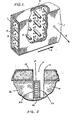
- FIG. 1 generally illustrate an embodiment of such drainage mat installable by the method of this invention.
- a water permeable fabric 1 envelops a core 2 having a plurality of substantially rigid fingers 4 extending from one side of a planar base 3.
- Such drainage mat is not bendable in the plane of base 3. In other words the mat is not bendable around axis 6 which is perpendicular to the planar base.
- Axis 5 indicates the alignment of the mat which would follow the length of a trench.
- Figure 2 illustrates a transverse cross-section of drainage mat in a vertical orientation in a trench 4 where the mat is used as highway edge drain.
- Trench 10 is cut into the shoulder 12 at the edge of highway pavement 14 into the highway base material 16.
- Opposing major surfaces 20 and 22 are aligned in a vertical orientation and opposing minor surfaces 24 and 26 define a top edge at surface 24 and a bottom edge at surface 26.
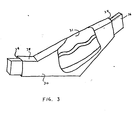
- FIG. 3 there is shown one embodiment of apparatus useful in carrying out the process of this invention for installing drainage mat in a trench as illustrated in Figure 2.
- apparatus comprises opposing parallel walls 30 and 31 which are separated by distance sufficient to allow the apparatus to readily slide (e.g. by pulling) in an excavated trench.
- the apparatus has an open inlet 32 for receiving drainage mat 36 and an open outlet 34 for delivering the drainage mat in a vertical orientation in the trench.
- Opposing walls 30 and 31 are separated sufficiently to allow the top edge of the drainage mat to deflect into a wave configuration as illustrated in the cutaway section of the apparatus.
- a first part of the mat is positioned with its base layer in a vertical plane above the trench, for instance at the inlet 32.
- the bottom edge of this first part of the mat is supported by a bearing surface (not shown) which defines the lower edge of inlet 32.
- the mat extends downwardly between walls 31 and 32 at an angle to the bottom of the trench.
- a second part of the mat is positioned with its base layer in a vertical plane at the bottom of the trench, for instance at the outlet 34.
- the upper edge of this second part of the mat is supported by a bearing surface, for instance panel 38 between walls 30 and 31.
- the bottom edge of the section of the mat between these first and second parts is maintained in a vertical plane.
- this section is deflected into a wave configuration to shorten the length of the top edge, causing the mat to follow a curve lying in the vertical plane.
- the mat is deposited in the bottom of the trench.
- the mat is passed through the curve by advancing such bearing surfaces at the inlet and outlet, for instance by pulling the apparatus in a trench, allowing the drainage mat to be deposited therein.
- the separation required between walls 30 and 31 depends on the curve to be followed by the mat between bearing surfaces and the thickness of mat.
- a drainage mat as illustrated in Figures 1 and 2 having a thickness (minor surface dimension) of about 1-1/8 inches (2.8 cm) and a height (major surface dimension) of about 11-3/8 inches (29 cm) was readily passed in a curve in a vertical plane between two walls of 1/4 inch (0.64 cm) thick steel plate.
- the walls were 2-12 inches (6.4 cm) apart.
- the bottom edge bearing surface was separated from the top edge bearing surface by a horizontal distance of 64 inches (162 cm) and a vertical distance of 15-1 ⁇ 2 inches (39 cm).
- Such drainage mat can be readily installed in a trench slightly wider than 3 inches (7.6 cm). With a greater horizontal distance between bearing surfaces, the separation between walls can be reduced permitting installation in even narrower trenches.
- the walls can be curved at elevations above the trench to facilitate feeding the drainage mat to the vertical section of the apparatus where the mat follows a curved path to the bottom of the trench.
- the apparatus generally described herein can be advantageously integrated with trenching means, e.g. be provided with a plow blade which is pulled to excavate a narrow trench.
Landscapes
- Engineering & Computer Science (AREA)
- Civil Engineering (AREA)
- Structural Engineering (AREA)
- General Engineering & Computer Science (AREA)
- Architecture (AREA)
- Life Sciences & Earth Sciences (AREA)
- Agronomy & Crop Science (AREA)
- Mechanical Engineering (AREA)
- Sewage (AREA)
- Retaining Walls (AREA)
Applications Claiming Priority (2)
| Application Number | Priority Date | Filing Date | Title |
|---|---|---|---|
| US72855985A | 1985-04-29 | 1985-04-29 | |
| US728559 | 1985-04-29 |
Publications (2)
| Publication Number | Publication Date |
|---|---|
| EP0200707A2 true EP0200707A2 (de) | 1986-11-05 |
| EP0200707A3 EP0200707A3 (de) | 1987-09-30 |
Family
ID=24927341
Family Applications (1)
| Application Number | Title | Priority Date | Filing Date |
|---|---|---|---|
| EP86870059A Withdrawn EP0200707A3 (de) | 1985-04-29 | 1986-04-28 | Einbau einer Strassen-Drainage-Matte |
Country Status (1)
| Country | Link |
|---|---|
| EP (1) | EP0200707A3 (de) |
Cited By (1)
| Publication number | Priority date | Publication date | Assignee | Title |
|---|---|---|---|---|
| WO2012051688A1 (en) * | 2010-10-22 | 2012-04-26 | Vitor Daniel Berno | Process of drain construction and drain |
Family Cites Families (2)
| Publication number | Priority date | Publication date | Assignee | Title |
|---|---|---|---|---|
| DE6753213U (de) * | 1968-07-12 | 1969-04-17 | Werner Vollmers | Vorrichtung zum einfuehren des spuelschlauches in draenagerohre |
| EP0124499B1 (de) * | 1983-03-31 | 1988-12-28 | Monsanto Company | Verfahren und Vorrichtung zum Installieren einer Dränungsmatte für eine Strasse |
-
1986
- 1986-04-28 EP EP86870059A patent/EP0200707A3/de not_active Withdrawn
Cited By (1)
| Publication number | Priority date | Publication date | Assignee | Title |
|---|---|---|---|---|
| WO2012051688A1 (en) * | 2010-10-22 | 2012-04-26 | Vitor Daniel Berno | Process of drain construction and drain |
Also Published As
| Publication number | Publication date |
|---|---|
| EP0200707A3 (de) | 1987-09-30 |
Similar Documents
| Publication | Publication Date | Title |
|---|---|---|
| EP0206996B1 (de) | Seitenausbau für Dränrohrsystem und Verfahren zum Ausbauen einer fortgehenden Böschung eines Dränrohrsystems | |
| US5372457A (en) | Method and apparatus for installing drainage channels | |
| US3618329A (en) | Method for installing subsoil moisture barrier | |
| US6203245B1 (en) | Culvert end guard | |
| EP0200707A2 (de) | Einbau einer Strassen-Drainage-Matte | |
| US4061322A (en) | Jig for electrical conduit stubs | |
| KR20200017132A (ko) | 지반침하 방지용 루프강관 및 이를 이용한 터널 시공공법 | |
| JP2772618B2 (ja) | 電気ケーブル等収納可能の剛性防護柵およびその施工方法 | |
| GB1591332A (en) | Drainage of roads and highways | |
| US4597693A (en) | Method and apparatus for installing highway drainage mat | |
| CN218843116U (zh) | 封堵钢围檩和基坑侧壁的间隙的辅助装置 | |
| CN1132979C (zh) | 易于去除模板的装置 | |
| GB2109845A (en) | Drainage of highways | |
| CN213953598U (zh) | 用于盾构机的接收结构 | |
| CN214301440U (zh) | 中央分隔带生态预制装配式护栏安装结构 | |
| EP0348012A1 (de) | Verfahren zum Ausführen einer Spundwand und dazu gebrauchtes Hilfsprofil | |
| GB2268037A (en) | Laying fin drains. | |
| CA1213742A (en) | Method and apparatus for installing highway drainage mat | |
| JPH0792333A (ja) | 土砂崩壊検出センサ用光ファイバの敷設方法 | |
| IE48924B1 (en) | Improvements in or relating to kerb stones | |
| JP2021102886A (ja) | 歩車道境界ブロック | |
| JP7779545B2 (ja) | コンクリート製収納管路の構築工法 | |
| RU2818136C1 (ru) | Устройство для защиты и закрепления подводного трубопровода | |
| CN215630491U (zh) | 雨水管道基槽结构 | |
| CN110331730B (zh) | 火山灰粉砂土路基边坡植草防护方法 |
Legal Events
| Date | Code | Title | Description |
|---|---|---|---|
| PUAI | Public reference made under article 153(3) epc to a published international application that has entered the european phase |
Free format text: ORIGINAL CODE: 0009012 |
|
| AK | Designated contracting states |
Kind code of ref document: A2 Designated state(s): AT BE CH DE FR GB IT LI LU NL SE |
|
| EL | Fr: translation of claims filed | ||
| PUAL | Search report despatched |
Free format text: ORIGINAL CODE: 0009013 |
|
| AK | Designated contracting states |
Kind code of ref document: A3 Designated state(s): AT BE CH DE FR GB IT LI LU NL SE |
|
| RHK1 | Main classification (correction) |
Ipc: E02B 11/00 |
|
| 17P | Request for examination filed |
Effective date: 19871228 |
|
| 17Q | First examination report despatched |
Effective date: 19881212 |
|
| STAA | Information on the status of an ep patent application or granted ep patent |
Free format text: STATUS: THE APPLICATION IS DEEMED TO BE WITHDRAWN |
|
| 18D | Application deemed to be withdrawn |
Effective date: 19890425 |
|
| RIN1 | Information on inventor provided before grant (corrected) |
Inventor name: RUSSELL, GERALD O. Inventor name: VAN DYKE, JAMES R. |