EP0200580B1 - Thermographiemaschine für den Reliefdruck - Google Patents
Thermographiemaschine für den Reliefdruck Download PDFInfo
- Publication number
- EP0200580B1 EP0200580B1 EP86400485A EP86400485A EP0200580B1 EP 0200580 B1 EP0200580 B1 EP 0200580B1 EP 86400485 A EP86400485 A EP 86400485A EP 86400485 A EP86400485 A EP 86400485A EP 0200580 B1 EP0200580 B1 EP 0200580B1
- Authority
- EP
- European Patent Office
- Prior art keywords
- conveyor
- strips
- powder
- cutting
- sheet
- Prior art date
- Legal status (The legal status is an assumption and is not a legal conclusion. Google has not performed a legal analysis and makes no representation as to the accuracy of the status listed.)
- Expired - Lifetime
Links
- 239000000843 powder Substances 0.000 claims description 21
- 238000001816 cooling Methods 0.000 claims description 12
- 238000010438 heat treatment Methods 0.000 claims description 7
- 239000012530 fluid Substances 0.000 claims description 5
- 238000000227 grinding Methods 0.000 claims description 4
- 238000007689 inspection Methods 0.000 claims description 3
- 238000007599 discharging Methods 0.000 claims 1
- 229920001296 polysiloxane Polymers 0.000 claims 1
- 230000001846 repelling effect Effects 0.000 claims 1
- 229920005989 resin Polymers 0.000 claims 1
- 239000011347 resin Substances 0.000 claims 1
- 239000007789 gas Substances 0.000 description 9
- 238000000034 method Methods 0.000 description 8
- 238000002844 melting Methods 0.000 description 7
- 230000008018 melting Effects 0.000 description 7
- 238000010410 dusting Methods 0.000 description 5
- 230000004927 fusion Effects 0.000 description 5
- 230000008569 process Effects 0.000 description 4
- 230000009466 transformation Effects 0.000 description 4
- 239000000463 material Substances 0.000 description 3
- 238000012545 processing Methods 0.000 description 3
- 230000002441 reversible effect Effects 0.000 description 2
- 229920002050 silicone resin Polymers 0.000 description 2
- 230000009471 action Effects 0.000 description 1
- 230000008859 change Effects 0.000 description 1
- 238000002485 combustion reaction Methods 0.000 description 1
- 230000018044 dehydration Effects 0.000 description 1
- 238000006297 dehydration reaction Methods 0.000 description 1
- 230000001627 detrimental effect Effects 0.000 description 1
- 238000011161 development Methods 0.000 description 1
- 239000000806 elastomer Substances 0.000 description 1
- 229920001821 foam rubber Polymers 0.000 description 1
- 239000011810 insulating material Substances 0.000 description 1
- 239000000155 melt Substances 0.000 description 1
- 238000012544 monitoring process Methods 0.000 description 1
- 230000003287 optical effect Effects 0.000 description 1
- 238000004806 packaging method and process Methods 0.000 description 1
- 230000001681 protective effect Effects 0.000 description 1
- 238000004064 recycling Methods 0.000 description 1
- 230000001105 regulatory effect Effects 0.000 description 1
- 230000002940 repellent Effects 0.000 description 1
- 239000005871 repellent Substances 0.000 description 1
- 230000000717 retained effect Effects 0.000 description 1
- 238000000926 separation method Methods 0.000 description 1
- 229920002379 silicone rubber Polymers 0.000 description 1
- 229910001220 stainless steel Inorganic materials 0.000 description 1
- 239000010935 stainless steel Substances 0.000 description 1
- 239000000126 substance Substances 0.000 description 1
- 230000001131 transforming effect Effects 0.000 description 1
- 239000002023 wood Substances 0.000 description 1
Images


Classifications
-
- B—PERFORMING OPERATIONS; TRANSPORTING
- B41—PRINTING; LINING MACHINES; TYPEWRITERS; STAMPS
- B41F—PRINTING MACHINES OR PRESSES
- B41F13/00—Common details of rotary presses or machines
- B41F13/54—Auxiliary folding, cutting, collecting or depositing of sheets or webs
- B41F13/56—Folding or cutting
-
- B—PERFORMING OPERATIONS; TRANSPORTING
- B41—PRINTING; LINING MACHINES; TYPEWRITERS; STAMPS
- B41F—PRINTING MACHINES OR PRESSES
- B41F23/00—Devices for treating the surfaces of sheets, webs, or other articles in connection with printing
- B41F23/04—Devices for treating the surfaces of sheets, webs, or other articles in connection with printing by heat drying, by cooling, by applying powders
- B41F23/06—Powdering devices, e.g. for preventing set-off
- B41F23/065—Powdering devices, e.g. for preventing set-off for thermography
Definitions
- the present invention relates to thermogravure machines for relief printing.
- Thermogravure or typo relief is a known process. It allows, from a typographic, offset or other printing, to obtain a relief printing imitating intaglio or stamping.
- the transformation into relief is simple and consists in sprinkling a sheet of freshly printed paper, with a powder having the property of melting under the action of heat and of forming, after fusion, a film in relief.
- printing presses according to their types and designs, are ordered from one side or the other.
- the printing press and the thermogravure machine work together and in the case where the cyclone side inspection door is opposite the control of the printing press, the operator of the two machines cannot easily monitor them.
- the support must substantially reach the melting point of the powder, that is to say approximately 90 to 100 ° centigrade.
- the heating time of the support mainly in the case of heavy grammage, requires ovens of great lengths to obtain rapid rates, of the average order of 6 to 8000 copies an hour.
- the hot air obtained by convection inside the oven at an adjustable temperature of the order of 300 to 450 ° centigrade.
- This air is not pulsed on the print.
- US-A-1,566,643 describes a machine for thermogravure for relief printing, which uses a mode of melting the powder film forming the relief using a gaseous fluid burnt at high temperature allowing very rapid melting in a brutal and selective heating on the surface of the support of the printed sheet.
- GB-A-775.885 relates to a cutting apparatus intended for processing a printed product directly from the printing press.
- the invention however, relates to a thermogravure machine, which results in special problems.
- thermogravure machines it was not considered possible to combine such a machine with an automatic cutting device, since the sheets of paper leaving the machine were deformed (combined, crumpled) and fragile. so that they did not allow themselves to be treated properly.
- the embossed prints were taken up by hand out of the machine to let them stand before being cut out in a separate cutting machine controlled by hand.
- the present invention aims to remedy these various drawbacks and inadequacies.
- thermogravure machine comprising characteristics according to claim 1.
- the advantageous embodiments are defined in the sub-claims.
- the printed and deformed paper strips After being transported by the dusting devices, heating and cooling, the printed and deformed paper strips are driven by a suction conveyor where they press against the conveyor and the main deformation is eliminated so that the strips can be aligned properly by the alignment device to be cut transversely into carts.
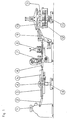
- FIG. 1 represents an overall view of a machine equipped with the various devices forming the subject of the invention.
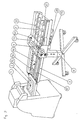
- FIG. 2 represents a perspective view of the first cutting device incorporated between the printing press and the thermogravure machine. This device makes it possible to slit the print in one direction before transforming it into relief.
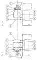
- FIG. 3 and 4 show a front view of a reversible cyclone.
- FIG. 5 represents a perspective view of a gas generator pulsed at high temperature.
- FIGS. 6A and 6B respectively represent a front view and a top view of a second cutting device, placed at the outlet of the thermogravure machine. This device allows cutting in the other direction, is removable and modular in several elements, depending on the number of unit poses to be cut.
- Figure 1 shows a complete chain to cut in two directions a print with different poses and transform it into relief.
- a printing press 1 deposits a print on the conveyor 2 of the first cutting device.
- This conveyor is provided with jogging devices 3 intended to line up, in a precise position, the print to be split, before engaging it under the sets of circular knives 4 for cutting.
- the strips are supported by guides 5, the role of which is to slightly space the strips before powdering them. This is necessary, because the bands that are too close together do not allow, after powdering, good suction through the cyclone, of the excess powder not retained by the printed parts.
- the powder falling into the curtain of the hopper rebounds and risks infiltrating the sides of the bands and moreover the suction between the joined bands is very bad and leaves a little powder on the powdering conveyor 7.
- Three millimeters minimum d space between the strips is essential for proper recycling of excess powder.
- the print passes through the powder block 6 and 7, passes under the pulsed hot gas generator 8 and under the cooling conveyor 9.
- the transformation into relief is then finished and the strips are taken up by suction on the vacuum conveyor 10 located at the outlet and above the cooling conveyor 9.
- the printed strips are conveyed and brought to determined and variable locations. They are then detached from the suction by fingers placed between the conveyor belts and released on the conveyor opposite one or more transverse cutting elements 11.
- Each element is removable and adapts to the neighboring element from where it takes its different movements.
- Each strip is, after jogging and cutting, received on a subdivided table 12, the height of which varies so as to keep the upper level of the stack of paper constant. This way of operating allows for example in the case of business cards printed by 18 poses, represented by three strips of six cards, to obtain 18 cards in relief at rates of 8 to 10,000 copies per hour, or approximately 150,000 cards to time.
- the set of two cutting devices is mounted on quadripods 13 and 14 with variable height so as to adapt to the height of any thermogravure machine.
- FIG. 2 shows in detail the first cutting device placed between the printing press and the thermogravure machine.
- a set of conveyors 2 mounted on a quadripod 14 whose height is adjustable as a function of the height of reception of the printing press 1, receives the printed matter 15 in several positions and routes it to a jogging conveyor.
- This conveyor consists of oblique rollers 16 the purpose of which is to move the printed matter towards a jogging belt 3 giving the cutting reference.
- This belt is rectified in thickness and supported on a shoe 17.
- the print passes under a path of balls 18 to be maintained during its jogging and cutting.
- the balls are made in a silicone resin because this material has the property of being repellent to fatty substances and therefore to printing ink, because in this specific case and unlike traditional cutting devices where the print is cut after transformation into relief, the ink is wet and cannot be brought into contact with usual materials without risk of postponing its printing and of contaminating the print and the jogging rollers.
- the strips are then cut using sets of circular knives 4, protected in operation by a tilting cover 19.
- An electric switch 19A deactivates the drive of the assembly when the protective cover 19 is tilted.
- the cut strips 20 fit into the positioning and separation slides 21 intended to create a space between each strip before dusting.
- the rollers 22 for driving and holding the bands 20 are also and for the same reasons as explained above, made in a silicone resin or elastomer.
- the entire device is actuated using a DC gear motor 23 whose speed is adjustable by means of a variable autotransformer 23A.
- Figures 3 and 4 show, in front view, a cyclone with two operating positions.
- the body of cylcone 24 has two symmetrical openings 24A and the like.
- the vacuum cleaner 25 and the inspection door of the cyclone 24B provided with fixing hooks 24C allowing them to hang indifferently on one side or the other of the cyclone.
- a flexible sheath 25A for powering the motor easily follows the motor in the event of a change in its location.
- a thick 25B rubber foam (about 10 millimeters) seals between the volute of the vacuum cleaner and the side walls of the cyclone.
- FIG. 5 shows, seen in perspective, a high temperature pulsed gas generator.
- a metallic conveyor 26 with tight meshes circulates on a refractory stainless steel box 26A, provided inside with heat insulating material.
- the powdered print 15 runs on the conveyor 26 and quickly passes under the generator 8 where the fusion takes place instantaneously.
- the generator consists of one or more burners 27, depending on the rates to be obtained.
- Diffusers (27A) channel the hot gases.
- the pressurized gas 27C passes through a regulating regulator 27D from which it emerges at approximately 20 grams of pressure per cm2. It is then channeled and introduced into a mixer 27E where the air with which it mixes arrives via another orifice and coming from the fan 27F. This air is distributed at a pressure of approximately 10 grams cm2.
- the gaseous fluid unlike the convection oven where the print passes through a mass of hot air without pressure, the gaseous fluid, even under slight pressure, instantly impregnates the film of powder and immediately melts it, whatever the thickness of the support.
- gas generator can be replaced by a forced air generator or the like.
- the pressure of the heated gaseous fluid must be low, otherwise the film constituting the relief will be deformed.
- FIG. 6A represents a front view of the cutting device placed at the outlet of the cooling conveyor.
- a conveyor 10 provided with conveyor belts between which a vacuum is created by means of the suction box 10A supplied by the vacuum cleaner 10B is placed at the end and above the cooling conveyor 9.
- the printed strips to be cut 15 are flattened on the conveyor 10 and are conveyed to their respective orientable stops 10C that detach them from the conveyor 10 and cause them to fall onto the conveyors 28 for input of the cutting devices 11.
- Each device is integral and includes all the elements necessary for slitting a strip.
- the printer can be equipped with one or more cutting devices.
- the first device is driven and transmits its movement to the devices in FIG. 6B which operates as follows:
- the input conveyor 28 conveys the strip 25 towards the jogging conveyor constituted by oblique rollers 28 A whose function is to move the print to a jogging belt 28B giving the cutting reference.
- the print passes under a ball path 28C to be maintained during its jogging and cutting.
- the cutting as in the cutting device placed at the entry of the thermogravure machine is carried out using circular knives 11 and the printed matter 15 cut out are received on a reception table 12, the upper level of which is maintained at constant level by the combination of a known device of optical transmitter and receiver 12A and 12B working with a geared motor acting intermittently on a gear 20 secured to the reception table and bearing on rack 29A.
- the assembly is also mounted on a robust quadripod 13 with variable height, fitted with wheels.
- the circular knives being removable, this latter device can be used in parallel with the good reception of large printed matter such as envelopes or the like. All of these improvements to these machines make them more complete and provide their user with ease of use which promotes the development of this process.
- making the method of melting the powder more selective opens up a new way of applying the process by making it possible to decorate in relief very thick materials such as wood, agglomerate, etc.
Landscapes
- Engineering & Computer Science (AREA)
- Mechanical Engineering (AREA)
- Printing Methods (AREA)
- Supply, Installation And Extraction Of Printed Sheets Or Plates (AREA)
Claims (5)
- Thermogravurmaschine für Hochdruck, in Kombination bestehend aus:
Einer Transporteinrichtung (2, 6, 26), die aus einer Druckereipresse (1) ein bedrucktes Blatt Papier (15) mit feuchter Druckfarbe aufnimmt und das Blatt (15) in Längsrichtung transportiert;
einer Längsschneidevorrichtung (4), die auf der Transporteinrichtung angeordnet ist und das bedruckte Blatt Papier in mehrere Längsstreifen (20) schneidet, wenn das Blatt mit noch feuchter Druckfarbe von der Transporteinrichtung vorgeschoben wird;
einer auf der Transporteinrichtung angeordneten Bestäubungsvorrichtung (6, 7), die auf die Streifen (20) während des Vorschubs derselben auf der Transporteinrichtung ein Pulver verteilt, sowie einem Zyklonabscheider (24) mit Sauggebläse (25), der das Pulver, abgesehen von den an der feuchten Druckfarbe auf den Streifen haftenden Pulveranteilen, von den Streifen entfernt, wobei der Zyklonabscheider eine Inspektionstür (24B) aufweist, die in Abhängigkeit vom Pressentyp auf der einen oder anderen Seite angeordnet ist;
einem auf der Transporteinrichtung angeordneten Heizgerät (8), das die Streifen (20) stoßweise bei hoher Temperatur mit einem gasförmigen Medium bestreicht, um das auf den Streifen verbliebende Pulver zwecks Schmelzung des Pulvers zu erhitzen;
einem auf der Transporteinrichtung angeordneten Kühlgerät (9) zur Kühlung der Streifen;
einem Unterdruckförderer (10) und Ausrichtungselementen (10C, 28, 28A, 28B, 28C) zur Verschiebung und Ausrichtung der aus dem Kühlgerät (9) kommenden Streifen;
und einer Querschneideeinrichtung (11), welche die korrekt ausgerichteten Streifen seitlich in Karten schneidet. - Thermogravurmaschine nach Anspruch 1, dadurch gekennzeichnet, daß die Schneidvorrichtungen (4, 11) abnehmbar sind.
- Thermogravurmaschine nach den Ansprüchen 1 und 2, dadurch gekennzeichnet, daß die Längsschneidevorrichtung (4) Bahnen mit Kugeln (18) und Antriebsrollen (22) aus Silikonharz oder Silikonelastomer, deren druckfarbenabstoßende Eigenschaften die Verschmierung der Auflager verhindern, aufweist.
- Thermogravurmaschine nach den Ansprüche 1, 2 und 3, dadurch gekennzeichnet, daß seitliche Gleitführungen die bedruckten Streifen nach dem Schneiden und vor der Bestäubung mit Pulver spreizen.
- Thermogravurmaschine nach Anspruch 1, dadurch gekennzeichnet, daß ein Lufterhitzer (27) ein gasförmiges Medium bei niedrigem Druck und hoher von 400 °C bis 1000 °C regelbarer Temperatur verteilt.
Priority Applications (1)
| Application Number | Priority Date | Filing Date | Title |
|---|---|---|---|
| CA000506390A CA1285816C (en) | 1985-04-12 | 1986-04-11 | Thermographic machine for relief printing |
Applications Claiming Priority (2)
| Application Number | Priority Date | Filing Date | Title |
|---|---|---|---|
| FR8505504 | 1985-04-12 | ||
| FR8505504A FR2580228B1 (fr) | 1985-04-12 | 1985-04-12 | Machine de thermogravure pour impression en relief |
Publications (2)
| Publication Number | Publication Date |
|---|---|
| EP0200580A1 EP0200580A1 (de) | 1986-11-05 |
| EP0200580B1 true EP0200580B1 (de) | 1991-09-11 |
Family
ID=9318155
Family Applications (1)
| Application Number | Title | Priority Date | Filing Date |
|---|---|---|---|
| EP86400485A Expired - Lifetime EP0200580B1 (de) | 1985-04-12 | 1986-03-07 | Thermographiemaschine für den Reliefdruck |
Country Status (4)
| Country | Link |
|---|---|
| US (1) | US4805531A (de) |
| EP (1) | EP0200580B1 (de) |
| DE (1) | DE3681333D1 (de) |
| FR (1) | FR2580228B1 (de) |
Families Citing this family (10)
| Publication number | Priority date | Publication date | Assignee | Title |
|---|---|---|---|---|
| US5213042A (en) * | 1992-02-25 | 1993-05-25 | The Nuventures Foundation | Printing process and apparatus |
| DE4213495A1 (de) * | 1992-04-24 | 1993-10-28 | Esselte Meto Int Gmbh | Markierungsstreifen |
| BE1007867A3 (nl) * | 1993-12-10 | 1995-11-07 | Koninkl Philips Electronics Nv | Werkwijze voor het verwarmen van een strookvormige drager in een oven en inrichting voor het bevestigen van tenminste een component op een strookvormige drager. |
| US5627578A (en) * | 1995-02-02 | 1997-05-06 | Thermotek, Inc. | Desk top printing of raised text, graphics, and braille |
| US5615614A (en) * | 1995-04-03 | 1997-04-01 | Van Pelt Equipment Corporation | Thermography process and apparatus |
| DE19653927C1 (de) * | 1996-10-21 | 1998-04-23 | Koenig & Bauer Albert Ag | Bogenbearbeitungsmaschine |
| DE19653403C2 (de) * | 1996-10-21 | 2001-05-10 | Koenig & Bauer Ag | Verfahren zum Transport von Bogen |
| US6119598A (en) * | 1998-05-18 | 2000-09-19 | Faust Thermographic Supply, Inc. | Apparatus and method for thermographic printing |
| US7300146B2 (en) | 2003-03-21 | 2007-11-27 | Hewlett-Packard Development Company, L.P. | Embossing using clear ink |
| US7048367B2 (en) | 2003-04-04 | 2006-05-23 | Hewlett-Packard Development Company, L.P. | Preconditioning media for embossing |
Family Cites Families (22)
| Publication number | Priority date | Publication date | Assignee | Title |
|---|---|---|---|---|
| US1566643A (en) * | 1925-12-22 | Chusetts | ||
| FR933765A (fr) * | 1945-12-08 | 1948-04-30 | C M Kemp Mfg Company | Brûleur à sécher l'encre d'imprimerie |
| FR1004368A (fr) * | 1949-01-04 | 1952-03-28 | Dispositif de suspension et de déplacement d'un poste mobile de contrôle dans une machine ou un appareil | |
| BE515611A (de) * | 1951-04-28 | |||
| GB775877A (en) * | 1954-02-24 | 1957-05-29 | Leonard Richard Frederick Smit | Machinery for use in conjunction with printing presses |
| DE1077052B (de) * | 1957-04-09 | 1960-03-03 | Jagenberg Werke Ag | Vorrichtung zum einstellbaren Befestigen von Trennschuhen zum Vereinzeln der Bogen in Querschneidern fuer laufende Papierbahnen |
| FR1334274A (fr) * | 1962-09-25 | 1963-08-02 | Color Metal A G | Perfectionnements apportés aux cylindres de transfert pour presses rotatives d'impression |
| FR1351740A (fr) * | 1963-02-28 | 1964-02-07 | Leipziger Buchbindereimaschine | Dispositif livreur pour machines de reliure |
| NL6501481A (de) * | 1964-02-15 | 1965-08-16 | ||
| US3813516A (en) * | 1969-12-29 | 1974-05-28 | Ibm | Apparatus for temperature control for a heated rotating cylinder |
| US4096801A (en) * | 1972-02-01 | 1978-06-27 | Martin John R | Register control method and apparatus |
| GB1435890A (en) * | 1972-05-26 | 1976-05-19 | Wadkin Ltd | Setting-up machinery under computer control |
| US4080158A (en) * | 1974-11-11 | 1978-03-21 | Canon Kabushiki Kaisha | Heat-fixing device |
| US3994221A (en) * | 1975-10-02 | 1976-11-30 | World Color Press, Inc. | Sheeter for use with printing press and adding provision for arresting, squaring and diverting of sheet |
| US4114021A (en) * | 1977-05-31 | 1978-09-12 | Rank Xerox, Ltd. | Heat roll fixing device for electrophotographic copying machine |
| US4118178A (en) * | 1977-07-21 | 1978-10-03 | Pitney-Bowes, Inc. | Xerographic fusing apparatus |
| US4121089A (en) * | 1977-07-29 | 1978-10-17 | International Business Machines Corporation | Apparatus for the reversal of a hot roll in a fusing assembly |
| DE3276471D1 (en) * | 1981-10-10 | 1987-07-09 | Basf Lacke & Farben | Flat-bed printing method |
| US4389114A (en) * | 1982-01-25 | 1983-06-21 | Pitney Bowes Inc. | Roll fixing apparatus for a copying machine |
| JPS58175662A (ja) * | 1982-04-09 | 1983-10-14 | Toshiba Mach Co Ltd | 印刷機の脱臭装置付き乾燥炉 |
| US4485294A (en) * | 1983-03-18 | 1984-11-27 | Phoenix Medical Corporation | Developer for photothermographic paper |
| US4501072A (en) * | 1983-07-11 | 1985-02-26 | Amjo, Inc. | Dryer and printed material and the like |
-
1985
- 1985-04-12 FR FR8505504A patent/FR2580228B1/fr not_active Expired
-
1986
- 1986-03-07 EP EP86400485A patent/EP0200580B1/de not_active Expired - Lifetime
- 1986-03-07 DE DE8686400485T patent/DE3681333D1/de not_active Expired - Fee Related
-
1987
- 1987-09-30 US US07/102,870 patent/US4805531A/en not_active Expired - Fee Related
Also Published As
| Publication number | Publication date |
|---|---|
| FR2580228B1 (fr) | 1987-05-22 |
| FR2580228A1 (fr) | 1986-10-17 |
| EP0200580A1 (de) | 1986-11-05 |
| US4805531A (en) | 1989-02-21 |
| DE3681333D1 (de) | 1991-10-17 |
Similar Documents
| Publication | Publication Date | Title |
|---|---|---|
| EP0200580B1 (de) | Thermographiemaschine für den Reliefdruck | |
| EP1494537B1 (de) | Automatisches band-kochgerät für pfannkuchen oder dergleichen | |
| FR2588252A1 (fr) | Machine et methode pour detacher des feuilles | |
| EP0044369B1 (de) | Thermographische Vorrichtung für Reliefdruck | |
| FR2731945A1 (fr) | Appareil d'enregistrement a jets d'encre | |
| FR2730139A1 (fr) | Appareil et procede pour decouper en elements des pieces pour des vetements faits sur mesure | |
| FR2591932A1 (fr) | Systeme de decoupage a laser | |
| FR2542293A1 (fr) | Appareil d'empilage de feuilles | |
| EP1215150A2 (de) | Vorrichtung zum Empfangen und Ausstossen von flächigen Gegenständen in einer Maschine zu ihrer Bearbeitung | |
| JP2008263807A (ja) | 生地計量コンベア及び生地計量切断装置 | |
| EP0000851A1 (de) | Automatische Vorrichtung zum Zerteilen eines thermoplastischen Schlauches und zum Überziehen von Behältern mittels dieser Schlauchteilen | |
| FR2703670A1 (fr) | Assembleuse de feuilles à cases superposées. | |
| CH627668A5 (fr) | Procede et dispositif de surmoulage de surfaces en materiau thermoplastique, notamment de semelles de skis. | |
| JPH08143010A (ja) | 包装装置 | |
| JPS63502420A (ja) | 印刷された弾性バンドの製造方法及び装置 | |
| EP0739721B1 (de) | Vorrichtung zum Handhaben von metallisierten, verbrauchten Bahnen in einer Maschine zum Übertragen von metallisierten Bildern auf flache Gegenstände | |
| KR100562995B1 (ko) | 라미네이터 | |
| EP2014464A1 (de) | Druckvorrichtung mit Mitteln zur Farbmengenverstellung | |
| FR2672241A1 (fr) | Imprimante par transfert thermique. | |
| EP1525146B1 (de) | Vorrichtung zum vorbereiten von materialbahnen wie auf thermoformanlagen erzeugten fangleisten | |
| EP0006276A1 (de) | Vorrichtung zum in gleiche Teile Schneiden eines sich bewegenden Metallbandes | |
| EP0549393A1 (de) | Verfahren und Anordnung zum Entfernen von Schutzfilmen von isolierten Platinen mit gedruckten Schaltungen | |
| CA1285816C (en) | Thermographic machine for relief printing | |
| BE823679A (fr) | Machine a former des sacs en matiere plastique | |
| JPS5952615A (ja) | 合成樹脂成形品の表面処理装置 |
Legal Events
| Date | Code | Title | Description |
|---|---|---|---|
| PUAI | Public reference made under article 153(3) epc to a published international application that has entered the european phase |
Free format text: ORIGINAL CODE: 0009012 |
|
| AK | Designated contracting states |
Kind code of ref document: A1 Designated state(s): BE CH DE GB IT LI NL SE |
|
| PUAB | Information related to the publication of an a document modified or deleted |
Free format text: ORIGINAL CODE: 0009199EPPU |
|
| PUAF | Information related to the publication of a search report (a3 document) modified or deleted |
Free format text: ORIGINAL CODE: 0009199SEPU |
|
| R17D | Deferred search report published (corrected) |
Effective date: 19861210 |
|
| RA1 | Application published (corrected) |
Date of ref document: 19861210 Kind code of ref document: A1 |
|
| 17P | Request for examination filed |
Effective date: 19861226 |
|
| 17Q | First examination report despatched |
Effective date: 19880315 |
|
| GRAA | (expected) grant |
Free format text: ORIGINAL CODE: 0009210 |
|
| AK | Designated contracting states |
Kind code of ref document: B1 Designated state(s): BE CH DE GB IT LI NL SE |
|
| REF | Corresponds to: |
Ref document number: 3681333 Country of ref document: DE Date of ref document: 19911017 |
|
| ITF | It: translation for a ep patent filed | ||
| GBT | Gb: translation of ep patent filed (gb section 77(6)(a)/1977) | ||
| PG25 | Lapsed in a contracting state [announced via postgrant information from national office to epo] |
Ref country code: GB Effective date: 19920307 |
|
| PG25 | Lapsed in a contracting state [announced via postgrant information from national office to epo] |
Ref country code: SE Effective date: 19920308 |
|
| PG25 | Lapsed in a contracting state [announced via postgrant information from national office to epo] |
Ref country code: LI Effective date: 19920331 Ref country code: CH Effective date: 19920331 Ref country code: BE Effective date: 19920331 |
|
| PLBE | No opposition filed within time limit |
Free format text: ORIGINAL CODE: 0009261 |
|
| STAA | Information on the status of an ep patent application or granted ep patent |
Free format text: STATUS: NO OPPOSITION FILED WITHIN TIME LIMIT |
|
| 26N | No opposition filed | ||
| BERE | Be: lapsed |
Owner name: SOC. ECAMO Effective date: 19920331 |
|
| PG25 | Lapsed in a contracting state [announced via postgrant information from national office to epo] |
Ref country code: NL Effective date: 19921001 |
|
| GBPC | Gb: european patent ceased through non-payment of renewal fee | ||
| NLV4 | Nl: lapsed or anulled due to non-payment of the annual fee | ||
| REG | Reference to a national code |
Ref country code: CH Ref legal event code: PL |
|
| PG25 | Lapsed in a contracting state [announced via postgrant information from national office to epo] |
Ref country code: DE Effective date: 19921201 |
|
| EUG | Se: european patent has lapsed |
Ref document number: 86400485.8 Effective date: 19921005 |
|
| PG25 | Lapsed in a contracting state [announced via postgrant information from national office to epo] |
Ref country code: IT Free format text: LAPSE BECAUSE OF NON-PAYMENT OF DUE FEES;WARNING: LAPSES OF ITALIAN PATENTS WITH EFFECTIVE DATE BEFORE 2007 MAY HAVE OCCURRED AT ANY TIME BEFORE 2007. THE CORRECT EFFECTIVE DATE MAY BE DIFFERENT FROM THE ONE RECORDED. Effective date: 20050307 |