EP0200544A2 - Kupplung für Walzwerke - Google Patents
Kupplung für Walzwerke Download PDFInfo
- Publication number
- EP0200544A2 EP0200544A2 EP86303280A EP86303280A EP0200544A2 EP 0200544 A2 EP0200544 A2 EP 0200544A2 EP 86303280 A EP86303280 A EP 86303280A EP 86303280 A EP86303280 A EP 86303280A EP 0200544 A2 EP0200544 A2 EP 0200544A2
- Authority
- EP
- European Patent Office
- Prior art keywords
- coupling box
- latch
- roll
- saddle
- support carrier
- Prior art date
- Legal status (The legal status is an assumption and is not a legal conclusion. Google has not performed a legal analysis and makes no representation as to the accuracy of the status listed.)
- Granted
Links
Images
Classifications
-
- B—PERFORMING OPERATIONS; TRANSPORTING
- B21—MECHANICAL METAL-WORKING WITHOUT ESSENTIALLY REMOVING MATERIAL; PUNCHING METAL
- B21B—ROLLING OF METAL
- B21B35/00—Drives for metal-rolling mills, e.g. hydraulic drives
- B21B35/14—Couplings, driving spindles, or spindle carriers specially adapted for, or specially arranged in, metal-rolling mills
- B21B35/148—Spindle carriers or balancers
Definitions
- This invention relates to rolling mills and, in particular, to the couplings by which the drive spindles are releasably connected to the ends of the driven rolls of the mill.
- each driven roll of a . rolling mill is connected at one end to its drive spindle by way of a coupling box which is connected through a joint to the spindle.
- the joint permits the spindles to be inclined to each other as the rolls are moved towards and away from each other and also permit rolls of different diameters to be employed.
- care has to be taken that the roll end does not become withdrawn from the coupling box.
- the roll end has to be withdrawn from the coupling box and, in order to reduce the roll change time as much as possible, it is desirable that the withdrawal of the roll end from the coupling box should be accomplished quickly.
- the present invention resides in the combination of a drive spindle having a coupling box at one end, the box being arranged to receive one end of a rolling mill roll and having a latch which serves to prevent withdrawal of a roll end inserted in the coupling box and a displaceable support carrier having provision for releasing the latch to enable the roll end to be withdrawn from the coupling box when the coupling box is supported on the support carrier.
- the coupling box is latched on to the roll end and this serves to prevent axial withdrawal of the roll end from the coupling box.
- the displaceable support carrier is displaced to a position where it supports the coupling box and, in this position, relative movement between the coupling box and the support carrier releases the latch to enable to roll end to be withdrawn from the coupling box.
- the carrier supports the coupling box until another roll end is introduced into the coupling box and, thereafter, the latch is reengaged on to the roll end to prevent withdrawal of the roll end from the coupling box.
- the latch is pivotally mounted on the coupling box and it is biased to its latching position.
- the latch remains biased into its latching position while the support carrier is moved into a position where it can support the coupling box and then engagement between a part of the latch and the support carrier causes the latch to pivot against the bias to release the roll end.
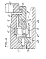
- reference 1 indicates part of a generally cylindrical coupling box having a central opening 3 for receiving an end of a rolling mill roll.
- the coupling box is mounted through a flexible joint to one end of a telescopic drive spindle (not shown).
- a drive pertains between the spindle and the roll.
- Reference 5 indicates a ring fitted around and projecting radially outwardly of the periphery of the roll end.
- the coupling box has at least one, and preferably of pair of, latches 9 which are pivotally mounted on the outside of the coupling box.
- Each latch is pivotally mounted on the coupling box by way of a pivot 10 intermediate the ends of the latch.
- a hook 11 At one end of the latch there is a hook 11 which enables the latch to fit around the outer edge of the ring 5 on the roll and thus prevent the roll from being withdrawn from the coupling box.
- At the opposite, inner, end of the latch there is a recess which receives one end of a coil spring 12 while the other end of the spring is located in a recess 13 formed in the wall of the coupling box.
- the spring is arranged to bias the latch in the anticlockwise direction, shown in Figure 2, against a stop 14.
- the coupling box On the outside of the latch, at the end to which the spring is attached, there is a button 15. Also on the coupling box, adjacent the button 15, there is an outwardly extending peg 19 which is aligned with the button 15. When the coupling box is provided with a pair of latches, it is convenient for there also to be a pair of pegs 19 and they are arranged to lie diametrically opposite to each other.
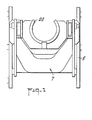
- a spindle support carrier is employed.
- the support carrier is indicated generally by reference 7 in Figure 1.
- the carrier is displaceable on a frame structure 8 in the direction of the axial length of the rolls.
- the support carrier has a saddle 20 which is capable of receiving and supporting the coupling box 1.
- hydraulic cylinders are provided for displacing the saddle vertically perpendicular to the axial length of the rolls. In this way, the saddle supporting a coupling box can be aligned with the end of a roll.
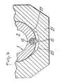
- the saddle has a forwardly projecting portion 2' and internally of this portion there is a groove 23 which extends around most of the internal periphery of the saddle. There is also a slot 25 which leads from the forward end of the projecting portion of the saddle to the recess 23.
- the carrier 7 When the mill is in use, and the rolls are being rotated, the carrier 7 is withdrawn away from the coupling box so as not to interfere with the coupling box or its spindle.
- the roll When, at roll changing time, the roll is to be removed from the coupling box, it is necessary to support the coupling box and, hence, the drive spindle, while the roll end is withdrawn from the coupling box.
- the spindles When the roll is to be withdrawn from the coupling box, the spindles are indexed into a predetermined angular position and, at this position, the spindle support carrier 7 is moved forwards towards the roll so that, as it moves towards the roll, the peg 19 enters into, and moves along, the slot 25 into the recess 23. At this time the button 15 is positioned in the slot 25.
- the spring 12 is urging the button outwardly and the roll end is still latched in the coupling box.
- the spindle is then rotated-relative to the support carrier so that the button 15 moves along an inclined surface 27 on the slot 25 of the carrier and this inclined surface forces the button to move inwardly against the action of the spring thus pivoting the latch about its pivot 10 to a position where the hook portion 11 of the latch is disconnected from the ring 5 at the roll end.
- the rotation of the coupling box is stopped and, with the coupling box supported on the support carrier, the spindle is retracted causing the carrier to be retracted due to the action of the peg 19 in the groove 23.
- the coupling box is drawn away from the roll end.
- a pair of support carriers are conveniently provided, one for each coupling of the two drive rolls.
Landscapes
- Engineering & Computer Science (AREA)
- Mechanical Engineering (AREA)
- Crushing And Grinding (AREA)
Applications Claiming Priority (2)
| Application Number | Priority Date | Filing Date | Title |
|---|---|---|---|
| GB8510976 | 1985-04-30 | ||
| GB858510976A GB8510976D0 (en) | 1985-04-30 | 1985-04-30 | Rolling mills |
Publications (3)
| Publication Number | Publication Date |
|---|---|
| EP0200544A2 true EP0200544A2 (de) | 1986-11-05 |
| EP0200544A3 EP0200544A3 (en) | 1987-05-20 |
| EP0200544B1 EP0200544B1 (de) | 1989-04-19 |
Family
ID=10578445
Family Applications (1)
| Application Number | Title | Priority Date | Filing Date |
|---|---|---|---|
| EP19860303280 Expired EP0200544B1 (de) | 1985-04-30 | 1986-04-30 | Kupplung für Walzwerke |
Country Status (3)
| Country | Link |
|---|---|
| EP (1) | EP0200544B1 (de) |
| DE (1) | DE3662843D1 (de) |
| GB (1) | GB8510976D0 (de) |
Family Cites Families (4)
| Publication number | Priority date | Publication date | Assignee | Title |
|---|---|---|---|---|
| DE7344551U (de) * | 1977-07-14 | Schloemann-Siemag Ag, 4000 Duesseldorf | Flachzapfenkupplung für Walzgerüste | |
| BE569805A (de) * | 1957-07-26 | |||
| DE1945612U (de) * | 1960-09-10 | 1966-09-08 | Siemag Siegener Masch Bau | Spindelstuhl fuer walzwerke. |
| DE1527724A1 (de) * | 1966-12-07 | 1970-02-12 | Schloemann Ag | Walzwerkskupplung,insbesondere fuer schwere Walzwerksantriebe |
-
1985
- 1985-04-30 GB GB858510976A patent/GB8510976D0/en active Pending
-
1986
- 1986-04-30 DE DE8686303280T patent/DE3662843D1/de not_active Expired
- 1986-04-30 EP EP19860303280 patent/EP0200544B1/de not_active Expired
Also Published As
| Publication number | Publication date |
|---|---|
| EP0200544B1 (de) | 1989-04-19 |
| DE3662843D1 (en) | 1989-05-24 |
| EP0200544A3 (en) | 1987-05-20 |
| GB8510976D0 (en) | 1985-06-05 |
Similar Documents
| Publication | Publication Date | Title |
|---|---|---|
| EP0909601B1 (de) | Werkzeughaltevorrichtung für werkzeugmaschinen | |
| JP3049059B2 (ja) | コンプレッサ―・バンドルの調節可能な挿入及び取り外しシステム | |
| JPH07206159A (ja) | ロール状物品の装填装置および装填方法 | |
| US4676448A (en) | Winding machine for winding and/or unwinding web-like guided materials | |
| CN216829743U (zh) | 一种薄壁管件外圆加工夹持工装 | |
| US4230286A (en) | Core holder for reeling | |
| US3485388A (en) | Core grab | |
| US4910860A (en) | Toolholder for a machine tool | |
| US4613092A (en) | Spindle assembly for winding machine | |
| EP0200544B1 (de) | Kupplung für Walzwerke | |
| GB2026049A (en) | Bobbin sleeve centering disc | |
| US5110233A (en) | Device for temporarily axially immobilizing a shaft in a body such as a steering column casing tube | |
| US4174077A (en) | Core holder for reeling | |
| GB1598761A (en) | Overload couplings | |
| AU657762B2 (en) | Tool for mounting to a parcel containing a coil of a continuous flexible object | |
| US4865261A (en) | Spooler system with temporary, larger diameter spooling surface | |
| CS265841B1 (en) | Cylindrical body especially core | |
| JP3837629B2 (ja) | 工具ポット | |
| JP2627096B2 (ja) | トーションばね引き出し方法および装置 | |
| JPH0631771B2 (ja) | 着脱自在の制御棒駆動軸案内体 | |
| JP2000506110A (ja) | 高速工作機械の取扱い装置と工具を支持する円筒状電動スピンドルと円筒状電動スピンドル保持装置との集合体 | |
| US3293842A (en) | Spindle mounted automatically doffable warp bobbin | |
| KR200308354Y1 (ko) | 러버슬리브교환장치 | |
| KR19980042431U (ko) | 러버 슬리이브(Rubber sleeve) 고정장치 | |
| US3356307A (en) | Doffing mechanism |
Legal Events
| Date | Code | Title | Description |
|---|---|---|---|
| PUAI | Public reference made under article 153(3) epc to a published international application that has entered the european phase |
Free format text: ORIGINAL CODE: 0009012 |
|
| AK | Designated contracting states |
Kind code of ref document: A2 Designated state(s): DE GB IT SE |
|
| PUAL | Search report despatched |
Free format text: ORIGINAL CODE: 0009013 |
|
| AK | Designated contracting states |
Kind code of ref document: A3 Designated state(s): DE GB IT SE |
|
| 17P | Request for examination filed |
Effective date: 19870626 |
|
| 17Q | First examination report despatched |
Effective date: 19880601 |
|
| GRAA | (expected) grant |
Free format text: ORIGINAL CODE: 0009210 |
|
| AK | Designated contracting states |
Kind code of ref document: B1 Designated state(s): DE GB IT SE |
|
| REF | Corresponds to: |
Ref document number: 3662843 Country of ref document: DE Date of ref document: 19890524 |
|
| ITF | It: translation for a ep patent filed | ||
| PLBE | No opposition filed within time limit |
Free format text: ORIGINAL CODE: 0009261 |
|
| STAA | Information on the status of an ep patent application or granted ep patent |
Free format text: STATUS: NO OPPOSITION FILED WITHIN TIME LIMIT |
|
| 26N | No opposition filed | ||
| ITTA | It: last paid annual fee | ||
| PGFP | Annual fee paid to national office [announced via postgrant information from national office to epo] |
Ref country code: GB Payment date: 19940425 Year of fee payment: 9 |
|
| PGFP | Annual fee paid to national office [announced via postgrant information from national office to epo] |
Ref country code: DE Payment date: 19940428 Year of fee payment: 9 |
|
| PGFP | Annual fee paid to national office [announced via postgrant information from national office to epo] |
Ref country code: SE Payment date: 19940429 Year of fee payment: 9 |
|
| EAL | Se: european patent in force in sweden |
Ref document number: 86303280.1 |
|
| PG25 | Lapsed in a contracting state [announced via postgrant information from national office to epo] |
Ref country code: GB Effective date: 19950430 |
|
| PG25 | Lapsed in a contracting state [announced via postgrant information from national office to epo] |
Ref country code: SE Effective date: 19950501 |
|
| GBPC | Gb: european patent ceased through non-payment of renewal fee |
Effective date: 19950430 |
|
| PG25 | Lapsed in a contracting state [announced via postgrant information from national office to epo] |
Ref country code: DE Effective date: 19960103 |
|
| EUG | Se: european patent has lapsed |
Ref document number: 86303280.1 |
|
| PG25 | Lapsed in a contracting state [announced via postgrant information from national office to epo] |
Ref country code: IT Free format text: LAPSE BECAUSE OF NON-PAYMENT OF DUE FEES;WARNING: LAPSES OF ITALIAN PATENTS WITH EFFECTIVE DATE BEFORE 2007 MAY HAVE OCCURRED AT ANY TIME BEFORE 2007. THE CORRECT EFFECTIVE DATE MAY BE DIFFERENT FROM THE ONE RECORDED. Effective date: 20050430 |