EP0200423A2 - Double block wire accumulator - Google Patents
Double block wire accumulator Download PDFInfo
- Publication number
- EP0200423A2 EP0200423A2 EP86302862A EP86302862A EP0200423A2 EP 0200423 A2 EP0200423 A2 EP 0200423A2 EP 86302862 A EP86302862 A EP 86302862A EP 86302862 A EP86302862 A EP 86302862A EP 0200423 A2 EP0200423 A2 EP 0200423A2
- Authority
- EP
- European Patent Office
- Prior art keywords
- block
- accumulator
- wire
- draw
- double
- Prior art date
- Legal status (The legal status is an assumption and is not a legal conclusion. Google has not performed a legal analysis and makes no representation as to the accuracy of the status listed.)
- Withdrawn
Links
- 239000003638 chemical reducing agent Substances 0.000 claims description 2
- 230000002950 deficient Effects 0.000 abstract description 12
- 238000005246 galvanizing Methods 0.000 description 3
- 238000003466 welding Methods 0.000 description 3
- 230000003247 decreasing effect Effects 0.000 description 1
- 239000000463 material Substances 0.000 description 1
- 238000005491 wire drawing Methods 0.000 description 1
Images

Classifications
-
- B—PERFORMING OPERATIONS; TRANSPORTING
- B21—MECHANICAL METAL-WORKING WITHOUT ESSENTIALLY REMOVING MATERIAL; PUNCHING METAL
- B21C—MANUFACTURE OF METAL SHEETS, WIRE, RODS, TUBES OR PROFILES, OTHERWISE THAN BY ROLLING; AUXILIARY OPERATIONS USED IN CONNECTION WITH METAL-WORKING WITHOUT ESSENTIALLY REMOVING MATERIAL
- B21C1/00—Manufacture of metal sheets, metal wire, metal rods, metal tubes by drawing
- B21C1/02—Drawing metal wire or like flexible metallic material by drawing machines or apparatus in which the drawing action is effected by drums
- B21C1/04—Drawing metal wire or like flexible metallic material by drawing machines or apparatus in which the drawing action is effected by drums with two or more dies operating in series
- B21C1/08—Drawing metal wire or like flexible metallic material by drawing machines or apparatus in which the drawing action is effected by drums with two or more dies operating in series in which the material does not slip on the drums
- B21C1/10—Drawing metal wire or like flexible metallic material by drawing machines or apparatus in which the drawing action is effected by drums with two or more dies operating in series in which the material does not slip on the drums with accumulation of material between consecutively-arranged dies
-
- B—PERFORMING OPERATIONS; TRANSPORTING
- B21—MECHANICAL METAL-WORKING WITHOUT ESSENTIALLY REMOVING MATERIAL; PUNCHING METAL
- B21C—MANUFACTURE OF METAL SHEETS, WIRE, RODS, TUBES OR PROFILES, OTHERWISE THAN BY ROLLING; AUXILIARY OPERATIONS USED IN CONNECTION WITH METAL-WORKING WITHOUT ESSENTIALLY REMOVING MATERIAL
- B21C1/00—Manufacture of metal sheets, metal wire, metal rods, metal tubes by drawing
- B21C1/02—Drawing metal wire or like flexible metallic material by drawing machines or apparatus in which the drawing action is effected by drums
- B21C1/14—Drums, e.g. capstans; Connection of grippers thereto; Grippers specially adapted for drawing machines or apparatus of the drum type; Couplings specially adapted for these drums
-
- B—PERFORMING OPERATIONS; TRANSPORTING
- B65—CONVEYING; PACKING; STORING; HANDLING THIN OR FILAMENTARY MATERIAL
- B65H—HANDLING THIN OR FILAMENTARY MATERIAL, e.g. SHEETS, WEBS, CABLES
- B65H51/00—Forwarding filamentary material
- B65H51/20—Devices for temporarily storing filamentary material during forwarding, e.g. for buffer storage
- B65H51/22—Reels or cages, e.g. cylindrical, with storing and forwarding surfaces provided by rollers or bars
Definitions
- This invention relates to a double block wire accumulator as is used in a wire processing line, such as wire drawing or wire galvanising, and in which a draw block is secured to a hollow outer shaft, an accumulator block is journalled on an inner shaft for free rotation in one direction only, a take-off ring is freely rotatable on the inner shaft between the draw block and the accumulator block and carries a turn-back pulley, a motor is provided for driving the hollow outer shaft and draw block at the processing line speed in the opposite direction to that in which the accumulator block is freely rotatable on the inner shaft, and means is provided for applying torque to the take-off ring in the direction of draw block rotation.
- Wire wound in one direction on the draw block passes round the turn-back pulley and is wound in the opposite direction on the accumulator block.
- torque applied to the take-off ring is counter-balanced by tension in the wire and causes the take-off ring and turn-back pulley to remain in a substantially fixed position.
- the take-off ring responds to an increase, or decrease in wire tension by rotating in one direction or the other, as required, to restore desired tension
- the accumulator block responds to differences between the processing line speed and speed of take-off from the accumulator block, e.g., by a driven reel, by speeding up or slowing down, as required, to release more or less wire until the speeds are again equal.
- the processing line is one of a plurality arranged side-by-side, e.g., in a wire galvanising plant where stoppage of the processing line causes defective material to be produced.
- the object of the invention is to provide a double block wire accumulator which allows of cutting out of a substantial length of defective wire without having to stop the processing line.
- a double block wire accumulator as described above is provided with means for overdriving the accumulator block for a period, means for stopping rotation of the accumulator block, and means for holding the accumulator block stationary for a period.
- Wire W wound in one direction on the draw block 2 passes round the turn-back pulley 7 and is wound in the opposite direction on the accumulator block 4, from which the wire is taken off, as by a take-off to be described presently.
- torque applied to the take-off ring 6 (by the means 9) is counter-balanced by tension in the wire and causes the take-off ring and turn-back pulley 7 to remain in a substantially fixed position.
- the take-off ring 6 responds to an increase or decrease in wire tension by rotating in one direction or the other, as required, to restore desired tension
- the accumulator block 4 responds to differences between the processing line speed and speed of take-off from the accumulator block by speeding up or slowing down, as required, to release more or less wire until the speeds are again equal.
- An independent electric motor 10 for overdriving the accumulator block 4 for a period is coupled to the inner shaft 5, and the motor 10 incorporates a brake 11 for stopping rotation of the accumulator block and for holding it stationary for a period.
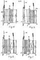
- the accumulator block 4 is overdriven until the defective portion is transferred from the draw block to the accumulator block (i.e., increasing the number of turns of wire on the accumulator block and decreasing the number of turns on the draw block, as in Figure 5), the accumulator block is stopped and held stationary while the defective portion DW of wire W is cut out and removed (with, meanwhile, the number of turns of wire on the draw block building up again, as in Figure 6) and the ends E of the remaining good wire connected together by welding (see Figure 7), and then the accumulator block is released to allow it to resume free rotation again on the inner shaft 5.
- the take-off from the accumulator block is driven by its own independent electric motor 13 through a variable speed gearbox 14, control of the speed ratio of which is effected in accordance with the number of turns of wire W on the accumulator block 4 as sensed by maximum and minimum micro-switches 15, 16 respectively.
- the wire W is led from the accumulator block 4 to the reel 12 via a swivelling guide pulley 17 and a swivelling traversing pulley 18 with a traversing drive 19 (not detailed beyond its input pulley 20) derived from the reel drive 13, 14, and a releasable wire clamp 21 is preferably provided between the two pulleys 17, 18.
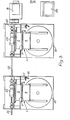
- independent electric motors (10 and 13) for overdriving the accumulator block 4 and the take-off or reel 12 is not only because these drives are independent of the drive for the draw block 2 (which is matched for speed to the feed of the processing line) but also becuase, as shown in Figure 3, the draw blocks 2 of a plurality of double block wire accumulators 1 arranged side-by-side (e.g., in a wire galvanising plant) can be driven by a common electric motor 8 through cardan shafts 22 and worm reducers 23, and there may be reduction gear 24 between the motor 8 and the first of the cardan shafts 22.
- a control console 25 for the row of double block wire accumulators 1 is also indicated in Figure 3.
Landscapes
- Engineering & Computer Science (AREA)
- Mechanical Engineering (AREA)
- Textile Engineering (AREA)
- Electric Cable Installation (AREA)
- Tension Adjustment In Filamentary Materials (AREA)
- Electrical Discharge Machining, Electrochemical Machining, And Combined Machining (AREA)
Abstract
A double block wire accumulator (1) having a draw block (2) on an outer shaft (3), an accumulator block (4) on an inner shaft (5), and a take-off ring (6) with a turn-back pulley (7) between the blocks (2,4), has a motor (10) for overdriving the accumulator block (4) for a period and a brake (11) for stopping rotation of the accumulator block and holding it stationary for a period, whereby a defective portion of wire can be transferred to the accumulator block (4), then the latter can be held stationary while the defective portion of wire is cut out and the ends of the remaining good wire welded together, without stopping the draw block (2), whereafter the accumulator block can be released, and - if need be - overdriven briefly, to restore normal running.
Description
- This invention relates to a double block wire accumulator as is used in a wire processing line, such as wire drawing or wire galvanising, and in which a draw block is secured to a hollow outer shaft, an accumulator block is journalled on an inner shaft for free rotation in one direction only, a take-off ring is freely rotatable on the inner shaft between the draw block and the accumulator block and carries a turn-back pulley, a motor is provided for driving the hollow outer shaft and draw block at the processing line speed in the opposite direction to that in which the accumulator block is freely rotatable on the inner shaft, and means is provided for applying torque to the take-off ring in the direction of draw block rotation. Wire wound in one direction on the draw block passes round the turn-back pulley and is wound in the opposite direction on the accumulator block. When desired wire tension is maintained, torque applied to the take-off ring is counter-balanced by tension in the wire and causes the take-off ring and turn-back pulley to remain in a substantially fixed position. The take-off ring responds to an increase, or decrease in wire tension by rotating in one direction or the other, as required, to restore desired tension, and the accumulator block responds to differences between the processing line speed and speed of take-off from the accumulator block, e.g., by a driven reel, by speeding up or slowing down, as required, to release more or less wire until the speeds are again equal.
- Thus, in the normal course, there will usually be an equal number of turns of wire on the draw block and the accumulator block, and for each turn of wire taken off the accumulator block there will be one turn transferred from the draw block to the accumulator block and a fresh turn is wound on to the draw block.
- In the event that a portion of wire is defective, e.g., incorrectly galvanised, it is necessary to stop the processing line while the defective portion is cut out and the ends of the remaining good wire connected together by welding. This is particularly disadvantageous when, as is frequently the case, the processing line is one of a plurality arranged side-by-side, e.g., in a wire galvanising plant where stoppage of the processing line causes defective material to be produced.
- The object of the invention is to provide a double block wire accumulator which allows of cutting out of a substantial length of defective wire without having to stop the processing line.
- According to the present invention, a double block wire accumulator as described above is provided with means for overdriving the accumulator block for a period, means for stopping rotation of the accumulator block, and means for holding the accumulator block stationary for a period.
- The manner of operation of the means of the invention, and preferred features thereof will now be described with reference to the accompanying drawings in which:-
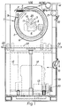
- Figure 1 is a front elevation of a double block wire accumulator in accordance with the invention;
- Figure 2 is an elevation from the left hand side of Figure 1;
- Figure 3 is a plan, on a smaller scale than Figures 1 and 2, showing how the draw blocks of a plurality of double block wire accumulators as in Figures 1 and 2 are driven by a common electric motor; and
- Figures 4 to 7 are diagrammatic plan views showing how the double block wire accumulator in accordance with the invention is operated to enable a defective portion of wire to be cut out.
- In Figures 1 and 2 a double
block wire accumulator 1 for wire W in a processing line comprises in known manner, adraw block 2 secured to a hollow outer shaft 3, anaccumulator block 4 journalled on aninner shaft 5 for free rotation in one direction only, a take-off ring 6 freely rotatable on theinner shaft 5 between thedraw block 2 and theaccumulator block 4 and carrying a turn-back pulley 7, a motor 8 (see Figure 3) for driving the hollow outer shaft 3 and drawblock 2 at the processing line speed in the opposite direction to that in which theaccumulator block 4 is freely rotatable on theinner shaft 5, and means 9 for applying torque to the take-off ring 6 in the direction of draw block rotation. - Wire W wound in one direction on the
draw block 2 passes round the turn-back pulley 7 and is wound in the opposite direction on theaccumulator block 4, from which the wire is taken off, as by a take-off to be described presently. When desired wire tension is maintained, torque applied to the take-off ring 6 (by the means 9) is counter-balanced by tension in the wire and causes the take-off ring and turn-back pulley 7 to remain in a substantially fixed position. The take-off ring 6 responds to an increase or decrease in wire tension by rotating in one direction or the other, as required, to restore desired tension, and theaccumulator block 4 responds to differences between the processing line speed and speed of take-off from the accumulator block by speeding up or slowing down, as required, to release more or less wire until the speeds are again equal. - Thus, in the normal course, there will usually be an equal number of turns of wire W on the
draw block 2 and the accumulator block 4 (as in Figure 4), and for each turn of wire taken off the accumular block there will be one turn transferred from the draw block to the accumulator block and a fresh turn is wound on to the draw block. - In the past it has been necessary to stop the processing line while any defective portion of wire was cut out and the ends of the remaining good wire connected together by welding. The means in accordance with the invention that are about to be described allow cutting out of a substantial length of defective wire without having to stop the processing line.
- An independent
electric motor 10 for overdriving theaccumulator block 4 for a period is coupled to theinner shaft 5, and themotor 10 incorporates a brake 11 for stopping rotation of the accumulator block and for holding it stationary for a period. - Thus, when a defective portion of wire DW (indicated by thinner lines) is detected on (or approaching) the
draw block 2, theaccumulator block 4 is overdriven until the defective portion is transferred from the draw block to the accumulator block (i.e., increasing the number of turns of wire on the accumulator block and decreasing the number of turns on the draw block, as in Figure 5), the accumulator block is stopped and held stationary while the defective portion DW of wire W is cut out and removed (with, meanwhile, the number of turns of wire on the draw block building up again, as in Figure 6) and the ends E of the remaining good wire connected together by welding (see Figure 7), and then the accumulator block is released to allow it to resume free rotation again on theinner shaft 5. - It is obviously necessary to stop the take-off from the accumulator block 4 (by means to be described presently) while the accumulator block is held stationary, and it may be necessary to overdrive the accumulator block again briefly if by the time the cut ends E of good wire have been connected to the
draw block 2 has "accumulated" more turns of wire than it normally carries (compare Figure 7 with Figure 4), this overdriving of the accumulator block being effected until there is again an equal number of turns of wire W on the draw block and the accumulator block (i.e., again as in Figure 4). - The take-off from the accumulator block, being in the illustrated embodiment a driven
reel 12, is driven by its own independentelectric motor 13 through avariable speed gearbox 14, control of the speed ratio of which is effected in accordance with the number of turns of wire W on theaccumulator block 4 as sensed by maximum andminimum micro-switches accumulator block 4 to thereel 12 via aswivelling guide pulley 17 and a swivelling traversingpulley 18 with a traversing drive 19 (not detailed beyond its input pulley 20) derived from thereel drive releasable wire clamp 21 is preferably provided between the twopulleys - The reference to "independent" electric motors (10 and 13) for overdriving the
accumulator block 4 and the take-off orreel 12 is not only because these drives are independent of the drive for the draw block 2 (which is matched for speed to the feed of the processing line) but also becuase, as shown in Figure 3, thedraw blocks 2 of a plurality of doubleblock wire accumulators 1 arranged side-by-side (e.g., in a wire galvanising plant) can be driven by a common electric motor 8 throughcardan shafts 22 andworm reducers 23, and there may be reduction gear 24 between the motor 8 and the first of thecardan shafts 22. Acontrol console 25 for the row of doubleblock wire accumulators 1 is also indicated in Figure 3.
Claims (8)
1. A double block wire accumulator (1) for use in a wire processing line and in which a draw block (2) is secured to a hollow outer shaft (3), an accumulator block (4) is journalled on an inner shaft (5) for free rotation in one direction only, a take-off ring (6) is freely rotatable on the inner shaft (5) between the draw block (2) and the accumulator block (4) and carries a turn-back pulley (7), a motor (8) is provided for driving the hollow outer shaft (3) and draw block (2) at the processing line speed in the opposite direction to that in which the accumulator block (4) is freely rotatable on the inner shaft (5), and means (9) is provided for applying torque to the take-off (6) ring in the direction of draw block rotation, characterised in that there is also provided means (10) for overdriving the accumulator block (4) for a period, means (11) for stopping rotation of the accumulator block (4), and means (11) for holding the accumulator block (4) stationary for a period.
2. A double block wire accumulator as in Claim 1, characterised in that the means (10) for overdriving the accumulator block (4) for a period is an independent electric motor coupled to the inner shaft (5).
3. A double block wire accumulator as in Claim 2, characterised in that the independent electric motor (10) incorporates a brake (11) for stopping rotation of the accumulator block (4) and for holding the accumulator block (4) stationary for a period.
4. A double block wire accumulator as in any of Claims 1 to 3, characterised in that a take-off (12) from the accumulator block is driven by its own independent electric motor (13) through a variable speed gearbox (14), control of the speed ratio of which is effected in accordance with the number of turns of wire (W) on the accumulator block (4) as sensed by maximum and minimum micro-switches (15, 16).
5. A double block wire accumulator as in Claim 4, characterised in that the take-off is a driven reel (12) and the wire (W) is led from the accumulator block (4) to the reel via a swivelling guide pulley (17) adjacent the accumulator block and a swivelling traversing pulley (18) with a traversing drive
(19) derived from the reel drive (13, 14).
6. A double block wire accumulator as in Claim 5, characterised in that a releasable wire clamp (21) is provided between the two pulleys (17, 18).
7. A plurality of double block wire accumulators (1) as in any one of Claims 1 to 6 arranged side-by-side and characterised in that the draw blocks (2) are driven by a common electric motor (8) through cardan shafts (22) and worm reducers (23).
Applications Claiming Priority (2)
| Application Number | Priority Date | Filing Date | Title |
|---|---|---|---|
| GB858510121A GB8510121D0 (en) | 1985-04-19 | 1985-04-19 | Double block wire accumulator |
| GB8510121 | 1985-04-19 |
Publications (2)
| Publication Number | Publication Date |
|---|---|
| EP0200423A2 true EP0200423A2 (en) | 1986-11-05 |
| EP0200423A3 EP0200423A3 (en) | 1987-05-13 |
Family
ID=10577943
Family Applications (1)
| Application Number | Title | Priority Date | Filing Date |
|---|---|---|---|
| EP86302862A Withdrawn EP0200423A3 (en) | 1985-04-19 | 1986-04-17 | Double block wire accumulator |
Country Status (2)
| Country | Link |
|---|---|
| EP (1) | EP0200423A3 (en) |
| GB (2) | GB8510121D0 (en) |
Citations (3)
| Publication number | Priority date | Publication date | Assignee | Title |
|---|---|---|---|---|
| DE912924C (en) * | 1950-05-15 | 1954-06-03 | Barron & Crowther Ltd | Wire drawing bench with several drawing stages |
| DE2111471A1 (en) * | 1971-03-10 | 1972-09-14 | Wilhelm Breitenbach Maschinenf | Wire drawing bench with several drawing stages (I) |
| US4511096A (en) * | 1983-11-14 | 1985-04-16 | Morgan Construction Company | Spinner drive for double block wire drawing machine |
-
1985
- 1985-04-19 GB GB858510121A patent/GB8510121D0/en active Pending
-
1986
- 1986-04-17 EP EP86302862A patent/EP0200423A3/en not_active Withdrawn
- 1986-04-17 GB GB08609428A patent/GB2174726B/en not_active Expired
Patent Citations (3)
| Publication number | Priority date | Publication date | Assignee | Title |
|---|---|---|---|---|
| DE912924C (en) * | 1950-05-15 | 1954-06-03 | Barron & Crowther Ltd | Wire drawing bench with several drawing stages |
| DE2111471A1 (en) * | 1971-03-10 | 1972-09-14 | Wilhelm Breitenbach Maschinenf | Wire drawing bench with several drawing stages (I) |
| US4511096A (en) * | 1983-11-14 | 1985-04-16 | Morgan Construction Company | Spinner drive for double block wire drawing machine |
Also Published As
| Publication number | Publication date |
|---|---|
| GB2174726A (en) | 1986-11-12 |
| GB8609428D0 (en) | 1986-05-21 |
| EP0200423A3 (en) | 1987-05-13 |
| GB2174726B (en) | 1988-06-15 |
| GB8510121D0 (en) | 1985-05-30 |
Similar Documents
| Publication | Publication Date | Title |
|---|---|---|
| EP0116174B1 (en) | Wire-like structure twisting machine | |
| SU967273A3 (en) | Apparatus for producing chopped bundles of glass fiber | |
| US11919739B2 (en) | Automatic cut and transfer coiler and or spooler | |
| EP0399243B1 (en) | Method and apparatus for avoiding pattern windings during the winding of a cross-wound bobbin | |
| CN1189260C (en) | Coiling controlling method | |
| EP0200423A2 (en) | Double block wire accumulator | |
| EP0768271A2 (en) | Winding apparatus for a continuously running thread | |
| EP0223989A2 (en) | Processing device, particularly for a textile machine | |
| US6321967B1 (en) | Device for drawing in a web of endless fabric | |
| US4809841A (en) | Apparatus for driving a passenger conveyor | |
| EP0407855B1 (en) | Planetary stranding machine | |
| DE3245574C2 (en) | Method for monitoring the texturing process in a friction false twist unit | |
| US3094833A (en) | Multi-strand cable fabricating apparatus and method | |
| DE3023257C2 (en) | ||
| DE4139587C2 (en) | Process for rewinding a cable or other winding material | |
| CA1156104A (en) | Combination of strand neutralizer, capstan and accumulator and closer | |
| DE19508928A1 (en) | Stranding machine | |
| EP0965553A3 (en) | Traverse apparatus having rotating wings | |
| DE3244015A1 (en) | Double-sided textile machine | |
| JPH02232156A (en) | Wire tension holding method in wire type cutter | |
| SU1400694A1 (en) | Drive for moving draw carriage | |
| SU820951A1 (en) | Apparatus for cutting strip at small-section rolling mill | |
| JPS57189971A (en) | Method of and device for variable speed traverse | |
| DE728718C (en) | Shear and tree machine with directly driven boom and upstream measuring drum carried along by the threads | |
| SU743794A1 (en) | Plant for cutting rolled strip |
Legal Events
| Date | Code | Title | Description |
|---|---|---|---|
| PUAI | Public reference made under article 153(3) epc to a published international application that has entered the european phase |
Free format text: ORIGINAL CODE: 0009012 |
|
| AK | Designated contracting states |
Kind code of ref document: A2 Designated state(s): AT BE CH DE FR GB IT LI LU NL SE |
|
| PUAL | Search report despatched |
Free format text: ORIGINAL CODE: 0009013 |
|
| AK | Designated contracting states |
Kind code of ref document: A3 Designated state(s): AT BE CH DE FR GB IT LI LU NL SE |
|
| STAA | Information on the status of an ep patent application or granted ep patent |
Free format text: STATUS: THE APPLICATION IS DEEMED TO BE WITHDRAWN |
|
| 18D | Application deemed to be withdrawn |
Effective date: 19871116 |
|
| RIN1 | Information on inventor provided before grant (corrected) |
Inventor name: NEWBOLT, JOHN DAVID |