EP0200423A2 - Drahtspeicher mit Doppeltrommel - Google Patents
Drahtspeicher mit Doppeltrommel Download PDFInfo
- Publication number
- EP0200423A2 EP0200423A2 EP86302862A EP86302862A EP0200423A2 EP 0200423 A2 EP0200423 A2 EP 0200423A2 EP 86302862 A EP86302862 A EP 86302862A EP 86302862 A EP86302862 A EP 86302862A EP 0200423 A2 EP0200423 A2 EP 0200423A2
- Authority
- EP
- European Patent Office
- Prior art keywords
- block
- accumulator
- wire
- draw
- double
- Prior art date
- Legal status (The legal status is an assumption and is not a legal conclusion. Google has not performed a legal analysis and makes no representation as to the accuracy of the status listed.)
- Withdrawn
Links
Images

Classifications
-
- B—PERFORMING OPERATIONS; TRANSPORTING
- B21—MECHANICAL METAL-WORKING WITHOUT ESSENTIALLY REMOVING MATERIAL; PUNCHING METAL
- B21C—MANUFACTURE OF METAL SHEETS, WIRE, RODS, TUBES, PROFILES OR LIKE SEMI-MANUFACTURED PRODUCTS OTHERWISE THAN BY ROLLING; AUXILIARY OPERATIONS USED IN CONNECTION WITH METAL-WORKING WITHOUT ESSENTIALLY REMOVING MATERIAL
- B21C1/00—Manufacture of metal sheets, wire, rods, tubes or like semi-manufactured products by drawing
- B21C1/02—Drawing metal wire or like flexible metallic material by drawing machines or apparatus in which the drawing action is effected by drums
- B21C1/04—Drawing metal wire or like flexible metallic material by drawing machines or apparatus in which the drawing action is effected by drums with two or more dies operating in series
- B21C1/08—Drawing metal wire or like flexible metallic material by drawing machines or apparatus in which the drawing action is effected by drums with two or more dies operating in series in which the material does not slip on the drums
- B21C1/10—Drawing metal wire or like flexible metallic material by drawing machines or apparatus in which the drawing action is effected by drums with two or more dies operating in series in which the material does not slip on the drums with accumulation of material between consecutively-arranged dies
-
- B—PERFORMING OPERATIONS; TRANSPORTING
- B21—MECHANICAL METAL-WORKING WITHOUT ESSENTIALLY REMOVING MATERIAL; PUNCHING METAL
- B21C—MANUFACTURE OF METAL SHEETS, WIRE, RODS, TUBES, PROFILES OR LIKE SEMI-MANUFACTURED PRODUCTS OTHERWISE THAN BY ROLLING; AUXILIARY OPERATIONS USED IN CONNECTION WITH METAL-WORKING WITHOUT ESSENTIALLY REMOVING MATERIAL
- B21C1/00—Manufacture of metal sheets, wire, rods, tubes or like semi-manufactured products by drawing
- B21C1/02—Drawing metal wire or like flexible metallic material by drawing machines or apparatus in which the drawing action is effected by drums
- B21C1/14—Drums, e.g. capstans; Connection of grippers thereto; Grippers specially adapted for drawing machines or apparatus of the drum type; Couplings specially adapted for these drums
-
- B—PERFORMING OPERATIONS; TRANSPORTING
- B65—CONVEYING; PACKING; STORING; HANDLING THIN OR FILAMENTARY MATERIAL
- B65H—HANDLING THIN OR FILAMENTARY MATERIAL, e.g. SHEETS, WEBS, CABLES
- B65H51/00—Forwarding filamentary material
- B65H51/20—Devices for temporarily storing filamentary material during forwarding, e.g. for buffer storage
- B65H51/22—Reels or cages, e.g. cylindrical, with storing and forwarding surfaces provided by rollers or bars
Definitions
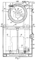
- This invention relates to a double block wire accumulator as is used in a wire processing line, such as wire drawing or wire galvanising, and in which a draw block is secured to a hollow outer shaft, an accumulator block is journalled on an inner shaft for free rotation in one direction only, a take-off ring is freely rotatable on the inner shaft between the draw block and the accumulator block and carries a turn-back pulley, a motor is provided for driving the hollow outer shaft and draw block at the processing line speed in the opposite direction to that in which the accumulator block is freely rotatable on the inner shaft, and means is provided for applying torque to the take-off ring in the direction of draw block rotation.
- Wire wound in one direction on the draw block passes round the turn-back pulley and is wound in the opposite direction on the accumulator block.
- torque applied to the take-off ring is counter-balanced by tension in the wire and causes the take-off ring and turn-back pulley to remain in a substantially fixed position.
- the take-off ring responds to an increase, or decrease in wire tension by rotating in one direction or the other, as required, to restore desired tension
- the accumulator block responds to differences between the processing line speed and speed of take-off from the accumulator block, e.g., by a driven reel, by speeding up or slowing down, as required, to release more or less wire until the speeds are again equal.
- the processing line is one of a plurality arranged side-by-side, e.g., in a wire galvanising plant where stoppage of the processing line causes defective material to be produced.
- the object of the invention is to provide a double block wire accumulator which allows of cutting out of a substantial length of defective wire without having to stop the processing line.
- a double block wire accumulator as described above is provided with means for overdriving the accumulator block for a period, means for stopping rotation of the accumulator block, and means for holding the accumulator block stationary for a period.
- Wire W wound in one direction on the draw block 2 passes round the turn-back pulley 7 and is wound in the opposite direction on the accumulator block 4, from which the wire is taken off, as by a take-off to be described presently.
- torque applied to the take-off ring 6 (by the means 9) is counter-balanced by tension in the wire and causes the take-off ring and turn-back pulley 7 to remain in a substantially fixed position.
- the take-off ring 6 responds to an increase or decrease in wire tension by rotating in one direction or the other, as required, to restore desired tension
- the accumulator block 4 responds to differences between the processing line speed and speed of take-off from the accumulator block by speeding up or slowing down, as required, to release more or less wire until the speeds are again equal.
- An independent electric motor 10 for overdriving the accumulator block 4 for a period is coupled to the inner shaft 5, and the motor 10 incorporates a brake 11 for stopping rotation of the accumulator block and for holding it stationary for a period.
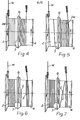
- the accumulator block 4 is overdriven until the defective portion is transferred from the draw block to the accumulator block (i.e., increasing the number of turns of wire on the accumulator block and decreasing the number of turns on the draw block, as in Figure 5), the accumulator block is stopped and held stationary while the defective portion DW of wire W is cut out and removed (with, meanwhile, the number of turns of wire on the draw block building up again, as in Figure 6) and the ends E of the remaining good wire connected together by welding (see Figure 7), and then the accumulator block is released to allow it to resume free rotation again on the inner shaft 5.
- the take-off from the accumulator block is driven by its own independent electric motor 13 through a variable speed gearbox 14, control of the speed ratio of which is effected in accordance with the number of turns of wire W on the accumulator block 4 as sensed by maximum and minimum micro-switches 15, 16 respectively.
- the wire W is led from the accumulator block 4 to the reel 12 via a swivelling guide pulley 17 and a swivelling traversing pulley 18 with a traversing drive 19 (not detailed beyond its input pulley 20) derived from the reel drive 13, 14, and a releasable wire clamp 21 is preferably provided between the two pulleys 17, 18.
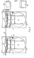
- independent electric motors (10 and 13) for overdriving the accumulator block 4 and the take-off or reel 12 is not only because these drives are independent of the drive for the draw block 2 (which is matched for speed to the feed of the processing line) but also becuase, as shown in Figure 3, the draw blocks 2 of a plurality of double block wire accumulators 1 arranged side-by-side (e.g., in a wire galvanising plant) can be driven by a common electric motor 8 through cardan shafts 22 and worm reducers 23, and there may be reduction gear 24 between the motor 8 and the first of the cardan shafts 22.
- a control console 25 for the row of double block wire accumulators 1 is also indicated in Figure 3.
Landscapes
- Engineering & Computer Science (AREA)
- Mechanical Engineering (AREA)
- Textile Engineering (AREA)
- Electrical Discharge Machining, Electrochemical Machining, And Combined Machining (AREA)
- Electric Cable Installation (AREA)
- Tension Adjustment In Filamentary Materials (AREA)
Applications Claiming Priority (2)
| Application Number | Priority Date | Filing Date | Title |
|---|---|---|---|
| GB858510121A GB8510121D0 (en) | 1985-04-19 | 1985-04-19 | Double block wire accumulator |
| GB8510121 | 1985-04-19 |
Publications (2)
| Publication Number | Publication Date |
|---|---|
| EP0200423A2 true EP0200423A2 (de) | 1986-11-05 |
| EP0200423A3 EP0200423A3 (de) | 1987-05-13 |
Family
ID=10577943
Family Applications (1)
| Application Number | Title | Priority Date | Filing Date |
|---|---|---|---|
| EP86302862A Withdrawn EP0200423A3 (de) | 1985-04-19 | 1986-04-17 | Drahtspeicher mit Doppeltrommel |
Country Status (2)
| Country | Link |
|---|---|
| EP (1) | EP0200423A3 (de) |
| GB (2) | GB8510121D0 (de) |
Family Cites Families (3)
| Publication number | Priority date | Publication date | Assignee | Title |
|---|---|---|---|---|
| DE912924C (de) * | 1950-05-15 | 1954-06-03 | Barron & Crowther Ltd | Drahtziehbank mit mehreren Ziehstufen |
| DE2111471A1 (de) * | 1971-03-10 | 1972-09-14 | Wilhelm Breitenbach Maschinenf | Drahtziehbank mit mehreren Ziehstufen(I) |
| US4511096A (en) * | 1983-11-14 | 1985-04-16 | Morgan Construction Company | Spinner drive for double block wire drawing machine |
-
1985
- 1985-04-19 GB GB858510121A patent/GB8510121D0/en active Pending
-
1986
- 1986-04-17 GB GB08609428A patent/GB2174726B/en not_active Expired
- 1986-04-17 EP EP86302862A patent/EP0200423A3/de not_active Withdrawn
Also Published As
| Publication number | Publication date |
|---|---|
| GB2174726B (en) | 1988-06-15 |
| EP0200423A3 (de) | 1987-05-13 |
| GB8609428D0 (en) | 1986-05-21 |
| GB2174726A (en) | 1986-11-12 |
| GB8510121D0 (en) | 1985-05-30 |
Similar Documents
| Publication | Publication Date | Title |
|---|---|---|
| EP0116174B1 (de) | Verseilmaschine für drahtförmiges Gut | |
| SU967273A3 (ru) | Устройство дл получени рубленных пучков из стекловолокна | |
| US11919739B2 (en) | Automatic cut and transfer coiler and or spooler | |
| EP0399243B1 (de) | Verfahren und Vorrichtung zum Vermeiden von Bildwicklungen beim Wickeln einer Kreuzspule | |
| EP0200423A2 (de) | Drahtspeicher mit Doppeltrommel | |
| DE3023257C2 (de) | ||
| CN1189260C (zh) | 卷绕控制方法 | |
| US6321967B1 (en) | Device for drawing in a web of endless fabric | |
| EP0407855B1 (de) | Korbverseilmaschine | |
| DE3245574C2 (de) | Verfahren zum Überwachen des Texturiervorgangs bei einem Friktionsfalschdrall-Aggregat | |
| US3094833A (en) | Multi-strand cable fabricating apparatus and method | |
| DE19508928C2 (de) | Einfach-Verseilmaschine | |
| DE4139587C2 (de) | Verfahren zum Umspulen eines Kabels oder anderen Wickelgutes | |
| CH439905A (de) | Bandspannvorrichtung | |
| EP0965553A3 (de) | Fadentraversiervorrichtung mit rotierenden Flügeln | |
| DE3244015A1 (de) | Doppelseitige textilmaschine | |
| CN1078603C (zh) | 胶片带机 | |
| DE59700876D1 (de) | Verfahren und Vorrichtung zum Betrieb von rotierenden Anlaufscheren | |
| SU1400694A1 (ru) | Привод перемещени каретки волочильного стана | |
| SU820951A1 (ru) | Устройство дл разбуривани полосыпРи пРОКАТКЕ HA МЕлКОСОРТНОМпРОКАТНОМ CTAHE | |
| JPS57189971A (en) | Method of and device for variable speed traverse | |
| DE728718C (de) | Scher- und Baeummaschine mit direkt angetriebenem Baum und vorgeschalteter, von den Faeden mitgenommener Messtrommel | |
| GB2119420A (en) | Wire stranding | |
| KR19980020200A (ko) | 타이어용 인너라이너를 권취하는 방법 및, 이에 따른 인너라이너 공급장치와 인너라이너 권취장치 | |
| SU1310056A1 (ru) | Многократный волочильный стан барабанного типа |
Legal Events
| Date | Code | Title | Description |
|---|---|---|---|
| PUAI | Public reference made under article 153(3) epc to a published international application that has entered the european phase |
Free format text: ORIGINAL CODE: 0009012 |
|
| AK | Designated contracting states |
Kind code of ref document: A2 Designated state(s): AT BE CH DE FR GB IT LI LU NL SE |
|
| PUAL | Search report despatched |
Free format text: ORIGINAL CODE: 0009013 |
|
| AK | Designated contracting states |
Kind code of ref document: A3 Designated state(s): AT BE CH DE FR GB IT LI LU NL SE |
|
| STAA | Information on the status of an ep patent application or granted ep patent |
Free format text: STATUS: THE APPLICATION IS DEEMED TO BE WITHDRAWN |
|
| 18D | Application deemed to be withdrawn |
Effective date: 19871116 |
|
| RIN1 | Information on inventor provided before grant (corrected) |
Inventor name: NEWBOLT, JOHN DAVID |