EP0199682B1 - Wasserklosettvorrichtung mit selbstreinigendem Becken - Google Patents
Wasserklosettvorrichtung mit selbstreinigendem Becken Download PDFInfo
- Publication number
- EP0199682B1 EP0199682B1 EP86830091A EP86830091A EP0199682B1 EP 0199682 B1 EP0199682 B1 EP 0199682B1 EP 86830091 A EP86830091 A EP 86830091A EP 86830091 A EP86830091 A EP 86830091A EP 0199682 B1 EP0199682 B1 EP 0199682B1
- Authority
- EP
- European Patent Office
- Prior art keywords
- bowl
- facility
- flush
- partition
- movable partition
- Prior art date
- Legal status (The legal status is an assumption and is not a legal conclusion. Google has not performed a legal analysis and makes no representation as to the accuracy of the status listed.)
- Expired
Links
- 238000004140 cleaning Methods 0.000 title claims abstract description 17
- XLYOFNOQVPJJNP-UHFFFAOYSA-N water Substances O XLYOFNOQVPJJNP-UHFFFAOYSA-N 0.000 title claims description 9
- 238000005192 partition Methods 0.000 claims abstract description 55
- 238000001035 drying Methods 0.000 claims abstract description 16
- 239000002699 waste material Substances 0.000 claims abstract description 5
- 238000011010 flushing procedure Methods 0.000 claims description 18
- 239000007788 liquid Substances 0.000 claims description 17
- 230000000249 desinfective effect Effects 0.000 claims description 13
- 239000007921 spray Substances 0.000 claims description 2
- 239000012530 fluid Substances 0.000 description 6
- 238000010276 construction Methods 0.000 description 2
- 230000015556 catabolic process Effects 0.000 description 1
- 230000002950 deficient Effects 0.000 description 1
- 238000010981 drying operation Methods 0.000 description 1
- 230000000694 effects Effects 0.000 description 1
- 238000010348 incorporation Methods 0.000 description 1
- 238000000034 method Methods 0.000 description 1
- 230000000737 periodic effect Effects 0.000 description 1
- 238000004659 sterilization and disinfection Methods 0.000 description 1
- 230000002463 transducing effect Effects 0.000 description 1
Images

Classifications
-
- E—FIXED CONSTRUCTIONS
- E03—WATER SUPPLY; SEWERAGE
- E03D—WATER-CLOSETS OR URINALS WITH FLUSHING DEVICES; FLUSHING VALVES THEREFOR
- E03D9/00—Sanitary or other accessories for lavatories ; Devices for cleaning or disinfecting the toilet room or the toilet bowl; Devices for eliminating smells
- E03D9/002—Automatic cleaning devices
Definitions
- the invention described herein relates to a water closest facility which features unassisted cleaning, inasmuch as it is provided with devices for flushing and disinfecting, and for drying the w.c. bowl.
- the problems that the invention sets out to overcome are those connected with automated public lavatories where general upkeep is the work of one attendant.
- such facilities envisage the use of a w.c. bowl which, following use by an individual on each single occasion, must be flushed, disinfected, and then dried, by entirely automatic means.
- the prior art embraces apparatus for flushing-and- disinfecting and drying the bowl of a w.c. which, following operation, can be stowed out of sight in a recess located in the wall against which the bowl is installed.
- the prior art apparatus swings down from a raised position, in which it is stowed inside the recess in the wall, to a lowered position in which contact is made with the bowl.
- the apparatus is provided with means for flushing and disinfecting and then drying the bowl, which are rotated by appropriate mechanical means, and operate only when the apparatus is in the lowered position.
- the prior art apparatus (EP-A-0,059,134) traverses from the stowed position, inside the recess, to a position outside the recess and above the bowl.
- the prior art also embraces water closets in which the bowl is tilted or turned toward flush-and-disinfect and drying apparatus, which in such an instance remains stationary, a working principle the exact opposite of the water closets first described.
- Such facilities present the same drawbacks as mentioned above, compounded further by the lack of a faultless watertight seal with which a bowl tilted about a horizontal axis needs to be provided.
- the additional problem arises of how the bowl may be covered during flush-and-disinfect and drying operations; this can be accomplished by incorporation of a movable lid associated with the bowl, though such an addition complicates an already complex construction still further.
- the prior art also embraces other types of water closet such as DE-C-708,165 wherein the problem of cleaning is partially overcome by providing single stationary toilet bowl with a set of four rotating toilet seats which are mechanically cleaned in sequence.
- the object of the invention is that of overcoming the drawbacks described above.
- the object of providing a water closet with a self-cleaning bowl is realized with a facility as described herein and as characterized by the appended claims; such a facility can be constructed in a far stronger and more durable fashion than that of prior art embodiments by virtue of the flush-and-disinfect and drying devices being installed in a service compartment that is separate from the closet and therefore easily accessible even when the closet is in use. Separating the closet from the service compartment enables embodiment of the various devices according to preference and for maximum efficiency, without having continually to bear in mind the necessity for their being stowed or otherwise moved any appreciable distance from the working position.
- the drying device for example, can be fitted simply and to best advantage direct to the partition wall inside the service compartment, or in the wall itself; what is more, the dimensions of such a device need not be binding in the least, and the device itself can be directed at a cleaned bowl exiting from the service compartment with no problems whatever.
- a further advantage offered by the invention is that it envisages the use of two interchangeable bowls; down time is therefore eliminated completely, inasmuch the soiled bowl in the closet can be replaced immediately following use by the bowl currently occupying the service compartment. This signifies that the time available for flushing and disinfecting the bowl can be increased considerably, while a vacant bowl remains continuously available for use.
- the provision of a spacious service compartment for flushing and disinfecting the bowl also allows of keeping the floor of the closet clean at all times, or at all events, free from splashes of liquid that might spill out during the cleaning operation.
- Yet another advantage of the invention is that it features fixed location of the jet, or the entire flush-and-disinfect device, or if not fixed, then spring-biased upward into an at-rest position and movable through a vertical path, with downward movement produced solely by pressure of the flushing and disinfecting liquid.
- Such a method of embodiment not only reduces the number of control components, from which defective operation or total breakdown of the facility can otherwise originate, but ensures better operation and renders the design more practical.
- a facility according to the invention is made still more practical and functional thanks to the adoption of a rotary jet which is operated by pressure of the flushing liquid and provided with a precision calibrated outlet that ensures an effective spray action covering the entire internal surface of the bowl.
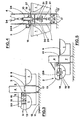
- a water closet facility with self-cleaning bowl consists essentially of at least one w.c. bowl 1 positioned against a fixed partition 4, with one automatic device 2 for flushing and disinfecting the bowl 1, and a further automatic device 3 for drying it.
- the fixed partition 4 separates the closet proper, denoted 5 and occupied by the single bowl 1, from a service compartment 6.
- the flush-and-disinfect device 2 and the drying device 3 are located inside the service compartment 6, mounted to the fixed partition 4.
- the fixed partition 4 is located directly above an opening 8 occupied by a movable partition 7, to which the bowl 1 is mounted.
- the movable partition 7 will carry two bowls 1 mounted back to back and symmetrical either side of the movable partition 7 in relation to a vertical median plane coinciding both with the axis of rotation of the movable partition itself and with the axis of a branched waste pipe 35 serving the two bowls 1.
- the flush-and-disinfect device 2 is provided with a jet 15 designed to project flushing and disinfecting liquid at the internal part of the bowl 1 from an outlet slot 16 (see Fig. 3 or 5); a shield is provided in the shape of a hood 13 designed to fit over the top of the bowl 1 occupying the service compartment 6.
- the jet 15 is a rotary type, operated by pressure of the flushing liquid flowing through it, and the outlet slot 16 is calibrated in such a way that flushing liquid projected assumes the aspect of a revolving blade of fluid which, sufficiently pressurized, will reach all points of the internal surface of the bowl 1 to good effect.
- the flush-and-disinfect device 2 might be embodied either fixed as in Fig. 5, or movable as in Figs. 2, 3 and 6.
- the device In the case of a fixed embodiment (Fig. 5) the device will be disposed at a height such as will permit its bottom edge 14 to ride over the uppermost edges 9 and 10 of the bowls 1 and the movable partition 7, respectively, whenever the movable partition is rotated, the two edges 9 and 10 in question occupying a common horizontal plane.
- the jet 15 in this instance would be best embodied telescopically (see positions as in Fig. 5, one of which 15a in broken line), with downward movement into the bowl 1 brought about preferably by pressure of the flushing liquid, nothing more.
- the jet 15 will move from a raised and spring-biased at-rest position, marginally above the bottom edge 14 of the hood 13, to a lowered working position inside the bowl 1 currently occupying the service compartment 6.
- the entire flush-and-disinfect device 2 might be movable through a vertical path, mounted thus to a frame 33 projecting from the fixed partition 4 (see Figs. 2 and 3) in such a way as to move downward when operated, likewise by pressure of the flushing liquid.
- the location of the jet 15 itself may be fixed, permanently occupying the position denoted 15a in Fig. 5, whilst the flush-and-disinfect device 2 is moved bodily from a raised, spring-biased at-rest position affording no obstruction to the bowls 1, which are thus free to rotate together with the movable partition 7 (see Fig. 2), down to a lowered working position in which the hood 13 fits over the bowl 1 currently occupying the service compartment 6 (see Fig. 3).
- the flush-and-disinfect device 2 might well be hinged, direct to the fixed partition 4 in this instance, and swung from a raised position in which no obstruction is offered to the bowls 1 (see Fig. 6, in which 13a denotes the raised hood), to a lowered position in which the hood 13 fits over the soiled bowl 1 (as in Fig. 6). Movement of the flush-and-disinfect device 2 in such an embodiment would be produced, say, by a fluid power cylinder 22 hinged to the fixed partition 4.
- the drying device 3 is incorporated to best advantage in the fixed partition 4, directed thus at the bowl 1 as it passes through.
- the device consists of two separate channels 23a and 23b disposed at either side of the axis about which the movable partition 7 rotates.
- the two channels 23a and 23b are embodied such that a clean bowl 1 passing beneath will be invested in its entirety by the flow of air produced, and are supplied independently by respective ducts 34a and 34b connecting with a common source.
- the ducts 34a and 34b are operated singly and in alternation by the appropriate signal from a control unit in such a way as to dry only a clean bowl 1 passing beneath either one of the two channels 23a or 23b; in a preferred embodiment, in fact, the two w.c. bowls 1 will swing back and forth through 180° between the closet and the service compartment.
- a water closet facility also comprises means 37 (see Fig. 4) for aligning and locking the movable partition 7 in position relative to the fixed partition 4, and skirtings 17 which extend or retract, when operated, from and toward the bottom of the movable partition 7, substantially at floor level, in order to allow passage of cleaning fluid directed from the floor of the closet 5 to the floor 12 of the service compartment 6.
- Means for alignment of the movable partition 7 consist essentially of at least one plunger 18 exhibit-cone frustum shape, which is integral with the rod 24a of a fluid power cylinder 24 mounted vertically to the fixed partition 4; the plunger 18 slides in a sleeve 26 integral with the fixed partition 4 and coaxial with the fluid power cylinder 24, and is designed to engage in a corresponding tapered socket 19 offered by the top of the movable partition 7, which is hollow.
- the skirtings 17 are hinged to the movable partition 7 as well as to an upright rod 21, in the latter instance via corresponding link-rods 20.
- the upright rod 21 is movable in a vertical direction, guided in such movement by the coaxial holes of a bushing 29, at bottom, and a cross-member 30 uppermost, integral with the movable partition 7; a spring 32 and thrust ring 32 are fitted to the upright rod 21 between the bushing 29 and the cross-member 30.
- the spring 32 urging against the bushing 29 on the one hand and against the thrust ring 31 on the other, pushes the upright rod 21 upwards in such a way that the skirtings 17 are forced to turn one toward the other and lift away from the floor 12, whereas the upright rod 21, aligned vertically with the cylinder rod 24a, is pushed down against the bias of the spring 32 by the self-same rod 24a whenever the plunger 18 is forced downwards and into engagement with the socket 19 in the movable partition 7.
- control unit aforementioned (not illustrated) will incorporate a variety of switching, transducing and timing components designed to coordinate all-automatic operation of a w.c. facility according to the invention.
- the at-rest position of the device 2 is that shown in Fig. 2, in the case of the vertically movable embodiment, or in Fig. 5, in the case of the fixed embodiment with movable jet positioned at 15a, or in Fig. 6, in the case of a hinged embodiment positioned at 13a.
- the movable partition 7 As the movable partition 7 turns, air is supplied to whichever channel 23a or 23b the clean bowl 1 passes beneath, such that the bowl is fully dried. Once the movable partition 7 has turned through 180°, it is stopped, and the cylinder or cylinders 24 will operate, causing the respective tapered plungers 18 to locate in the sockets 19 of the movable partition 7 and bring about its alignment. In descending, the rods 24a of the cylinders 24 urge downward on each upright rod 21 against the bias of the spring 32 so that the skirtings 17 are made to turn into their lowered position, aligned with the surfaces of the movable partition 7.
- the cylinder 24 will be actuated only when cleaning ofthe floor 12 has been completed, likewise automatically and by way of suitable apparatus, whereupon the cleaning liquid utilized will pass beneath the movable partition 7 and run out through the drain 11 in the service compartment 6.
- the flush-and-disinfect device 2 is moved into working position either by operation of the cylinder 22, in the case of a device 2 as in Fig. 6, or by supplying cleaning liquid in order to lower the jet 15 (as in Fig. 5) or the device 2 as a whole (as in Fig. 3).
- the supply of liquid is cut off and the device 2 returns naturally to the at-rest position (Figs. 3 and 5) or is returned by operation of the relative cylinder 22 (Fig. 6).
- the facility will now remain in this configuration until such time as the closet 5 is either vacated or re-utilized, whereupon the sequence of operations will be repeated.
Landscapes
- Health & Medical Sciences (AREA)
- Public Health (AREA)
- Epidemiology (AREA)
- Life Sciences & Earth Sciences (AREA)
- Engineering & Computer Science (AREA)
- Hydrology & Water Resources (AREA)
- Water Supply & Treatment (AREA)
- Sanitary Device For Flush Toilet (AREA)
- Bidet-Like Cleaning Device And Other Flush Toilet Accessories (AREA)
- Cookers (AREA)
- Apparatus For Disinfection Or Sterilisation (AREA)
Claims (9)
Priority Applications (1)
| Application Number | Priority Date | Filing Date | Title |
|---|---|---|---|
| AT86830091T ATE44566T1 (de) | 1985-04-19 | 1986-04-17 | Wasserklosettvorrichtung mit selbstreinigendem becken. |
Applications Claiming Priority (2)
| Application Number | Priority Date | Filing Date | Title |
|---|---|---|---|
| IT03408/85A IT1187359B (it) | 1985-04-19 | 1985-04-19 | Strttura con vaso autopulente per servizio igienico |
| IT340885 | 1985-04-19 |
Publications (3)
| Publication Number | Publication Date |
|---|---|
| EP0199682A2 EP0199682A2 (de) | 1986-10-29 |
| EP0199682A3 EP0199682A3 (en) | 1987-04-08 |
| EP0199682B1 true EP0199682B1 (de) | 1989-07-12 |
Family
ID=11106640
Family Applications (1)
| Application Number | Title | Priority Date | Filing Date |
|---|---|---|---|
| EP86830091A Expired EP0199682B1 (de) | 1985-04-19 | 1986-04-17 | Wasserklosettvorrichtung mit selbstreinigendem Becken |
Country Status (4)
| Country | Link |
|---|---|
| EP (1) | EP0199682B1 (de) |
| AT (1) | ATE44566T1 (de) |
| DE (1) | DE3664352D1 (de) |
| IT (1) | IT1187359B (de) |
Families Citing this family (14)
| Publication number | Priority date | Publication date | Assignee | Title |
|---|---|---|---|---|
| CH658491A5 (de) * | 1985-12-05 | 1986-11-14 | Jiri Faborsky | Dreh-toiletten-anlage. |
| FR2597524B1 (fr) * | 1986-04-17 | 1988-07-29 | Decaux Jean Claude | Module sanitaire a nettoyage automatique |
| FR2618469B1 (fr) * | 1987-07-24 | 1989-12-01 | Lambert Martial | Dispositif d'aisance a deux cuvettes a nettoyage automatique |
| IT1223216B (it) * | 1987-12-04 | 1990-09-19 | Coopsette Scrl | Servizio igienico a pulitura automatica con risciacquo comandabile, particolarmente per locali pubblici e simili |
| DE3941304A1 (de) * | 1989-12-14 | 1991-06-20 | Johannes Loebbert | Trockentoilette |
| DE4006676C2 (de) * | 1990-03-03 | 1994-01-20 | Otto Geb Kg | Sanitärzelle |
| DE4007507A1 (de) * | 1990-03-09 | 1991-09-12 | Klaus Dipl Ing Roemer | Spuelklosett |
| DE4118588A1 (de) * | 1991-06-06 | 1992-12-10 | Otto Geb Kg | Sanitaerzelle mit automatischer reinigungsvorrichtung fuer die toilettenschuessel |
| IT1269425B (it) * | 1994-01-13 | 1997-04-01 | Eco Program Srl | Disposizione e procedimento per pulire automaticamente un apparecchio sanitario |
| FR2772060B1 (fr) * | 1997-12-05 | 2000-02-25 | Jean Pierre Requena | Installation d'aisance a nettoyage automatique et a cuvette mobile en translation et son procede de nettoyage |
| RU2255185C1 (ru) * | 2004-02-20 | 2005-06-27 | Завалковский Григорий Наумович | Самоочищающийся туалет |
| DE102010016200A1 (de) | 2010-03-29 | 2011-09-29 | Brähmig Fluidautomation GmbH | Sanitärmodul und Verfahren zur automatischen Reinigung von Sanitärbecken für Sanitärzellen |
| NL2011149C2 (en) * | 2013-07-12 | 2015-01-13 | Claleco B V | Toilet system and method for cleaning a toilet system. |
| NL2011150C2 (en) * | 2013-07-12 | 2015-01-15 | Claleco B V | Toilet cleaning system and method for cleaning a toilet system. |
Family Cites Families (6)
| Publication number | Priority date | Publication date | Assignee | Title |
|---|---|---|---|---|
| DE208165C (de) * | ||||
| US3747129A (en) * | 1971-09-09 | 1973-07-24 | D Dyar | Automatic cleaning system for a habitable enclosure |
| US3919726A (en) * | 1974-12-04 | 1975-11-18 | Gen Electric | Water closet having a bowl and a wash means |
| JPS5398173A (en) * | 1977-02-07 | 1978-08-28 | Borukano Kk | Continuously usable incineration type toilet |
| FR2499124A1 (fr) * | 1981-02-05 | 1982-08-06 | Sato Associes | Unite sanitaire comportant des moyens de nettoyage |
| US4449258A (en) * | 1981-10-22 | 1984-05-22 | Remo Ackermann | Water-closet with rotary double pan |
-
1985
- 1985-04-19 IT IT03408/85A patent/IT1187359B/it active
-
1986
- 1986-04-17 AT AT86830091T patent/ATE44566T1/de not_active IP Right Cessation
- 1986-04-17 EP EP86830091A patent/EP0199682B1/de not_active Expired
- 1986-04-17 DE DE8686830091T patent/DE3664352D1/de not_active Expired
Also Published As
| Publication number | Publication date |
|---|---|
| EP0199682A3 (en) | 1987-04-08 |
| EP0199682A2 (de) | 1986-10-29 |
| IT8503408A0 (it) | 1985-04-19 |
| IT1187359B (it) | 1987-12-23 |
| DE3664352D1 (en) | 1989-08-17 |
| ATE44566T1 (de) | 1989-07-15 |
Similar Documents
| Publication | Publication Date | Title |
|---|---|---|
| EP0199682B1 (de) | Wasserklosettvorrichtung mit selbstreinigendem Becken | |
| CA1092751A (en) | Sanitary unit | |
| WO1997021002A1 (de) | Wasserklosett mit einer verschwenkbaren schüssel | |
| WO2017078386A1 (ko) | 비데용 밸브장치 | |
| JP2516190Y2 (ja) | 人体局部洗浄装置 | |
| US5279008A (en) | Sanitary cell with automatic cleaning device for the toilet bowl | |
| US6772451B2 (en) | Automatic device for washing a toilet seat ring | |
| EP0356691B1 (de) | Sanitärzelle für öffentliche Zwecke | |
| ES8404460A1 (es) | "perfeccionamientos en los aparatos sanitarios autolimpiantes" | |
| EP0509503B1 (de) | Sanitärzelle mit automatischer Reinigungsvorrichtung | |
| EP0319103B1 (en) | Self cleaning water closet | |
| CA2070480A1 (en) | Sanitary cell with cleaning appliances for toilet seat | |
| JP7482725B2 (ja) | 便器装置 | |
| US7269863B1 (en) | Automatic self-cleaning toilet | |
| JP3649001B2 (ja) | ボウル洗浄機能付便座を有する便器 | |
| CN215802084U (zh) | 智能小便池系统 | |
| KR20140076810A (ko) | 변좌 세척장치 | |
| JP2025056929A (ja) | 便座装置 | |
| CZ31974U1 (cs) | Stacionární zařízení pro automatické čištění podlah místností | |
| CN212561785U (zh) | 一种坐便器自动清洁系统及坐便器 | |
| CN113605506A (zh) | 智能小便池系统及工作方法 | |
| KR0122450Y1 (ko) | 좌변기의 자동 물 내림장치 | |
| CN216787342U (zh) | 一种坐便器清洗装置及智能卫生间 | |
| CN217191443U (zh) | 一种动物医药用药瓶消毒设备 | |
| KR102504443B1 (ko) | 절수형 친환경 좌변기 |
Legal Events
| Date | Code | Title | Description |
|---|---|---|---|
| PUAI | Public reference made under article 153(3) epc to a published international application that has entered the european phase |
Free format text: ORIGINAL CODE: 0009012 |
|
| AK | Designated contracting states |
Kind code of ref document: A2 Designated state(s): AT BE CH DE FR GB LI LU NL SE |
|
| PUAL | Search report despatched |
Free format text: ORIGINAL CODE: 0009013 |
|
| AK | Designated contracting states |
Kind code of ref document: A3 Designated state(s): AT BE CH DE FR GB LI LU NL SE |
|
| 17P | Request for examination filed |
Effective date: 19871008 |
|
| 17Q | First examination report despatched |
Effective date: 19880721 |
|
| GRAA | (expected) grant |
Free format text: ORIGINAL CODE: 0009210 |
|
| AK | Designated contracting states |
Kind code of ref document: B1 Designated state(s): AT BE CH DE FR GB LI LU NL SE |
|
| PG25 | Lapsed in a contracting state [announced via postgrant information from national office to epo] |
Ref country code: NL Effective date: 19890712 Ref country code: BE Effective date: 19890712 |
|
| REF | Corresponds to: |
Ref document number: 44566 Country of ref document: AT Date of ref document: 19890715 Kind code of ref document: T |
|
| REF | Corresponds to: |
Ref document number: 3664352 Country of ref document: DE Date of ref document: 19890817 |
|
| ET | Fr: translation filed | ||
| NLV1 | Nl: lapsed or annulled due to failure to fulfill the requirements of art. 29p and 29m of the patents act | ||
| PG25 | Lapsed in a contracting state [announced via postgrant information from national office to epo] |
Ref country code: SE Effective date: 19900201 |
|
| PG25 | Lapsed in a contracting state [announced via postgrant information from national office to epo] |
Ref country code: LU Free format text: LAPSE BECAUSE OF NON-PAYMENT OF DUE FEES Effective date: 19900430 |
|
| PLBE | No opposition filed within time limit |
Free format text: ORIGINAL CODE: 0009261 |
|
| STAA | Information on the status of an ep patent application or granted ep patent |
Free format text: STATUS: NO OPPOSITION FILED WITHIN TIME LIMIT |
|
| 26N | No opposition filed | ||
| PGFP | Annual fee paid to national office [announced via postgrant information from national office to epo] |
Ref country code: GB Payment date: 19930407 Year of fee payment: 8 |
|
| PGFP | Annual fee paid to national office [announced via postgrant information from national office to epo] |
Ref country code: FR Payment date: 19930408 Year of fee payment: 8 |
|
| PGFP | Annual fee paid to national office [announced via postgrant information from national office to epo] |
Ref country code: AT Payment date: 19930415 Year of fee payment: 8 |
|
| PGFP | Annual fee paid to national office [announced via postgrant information from national office to epo] |
Ref country code: CH Payment date: 19930427 Year of fee payment: 8 |
|
| PGFP | Annual fee paid to national office [announced via postgrant information from national office to epo] |
Ref country code: DE Payment date: 19930506 Year of fee payment: 8 |
|
| PG25 | Lapsed in a contracting state [announced via postgrant information from national office to epo] |
Ref country code: GB Effective date: 19940417 Ref country code: AT Effective date: 19940417 |
|
| PG25 | Lapsed in a contracting state [announced via postgrant information from national office to epo] |
Ref country code: LI Effective date: 19940430 Ref country code: CH Effective date: 19940430 |
|
| GBPC | Gb: european patent ceased through non-payment of renewal fee |
Effective date: 19940417 |
|
| PG25 | Lapsed in a contracting state [announced via postgrant information from national office to epo] |
Ref country code: FR Effective date: 19941229 |
|
| REG | Reference to a national code |
Ref country code: CH Ref legal event code: PL |
|
| PG25 | Lapsed in a contracting state [announced via postgrant information from national office to epo] |
Ref country code: DE Effective date: 19950103 |
|
| REG | Reference to a national code |
Ref country code: FR Ref legal event code: ST |