EP0199355A1 - Cassette de ruban encreur et mécanisme d'alimentation de ruban - Google Patents
Cassette de ruban encreur et mécanisme d'alimentation de ruban Download PDFInfo
- Publication number
- EP0199355A1 EP0199355A1 EP86105677A EP86105677A EP0199355A1 EP 0199355 A1 EP0199355 A1 EP 0199355A1 EP 86105677 A EP86105677 A EP 86105677A EP 86105677 A EP86105677 A EP 86105677A EP 0199355 A1 EP0199355 A1 EP 0199355A1
- Authority
- EP
- European Patent Office
- Prior art keywords
- ink ribbon
- cassette
- ink
- carriage
- ribbon
- Prior art date
- Legal status (The legal status is an assumption and is not a legal conclusion. Google has not performed a legal analysis and makes no representation as to the accuracy of the status listed.)
- Granted
Links
- 238000005452 bending Methods 0.000 description 2
- 241000723353 Chrysanthemum Species 0.000 description 1
- 235000005633 Chrysanthemum balsamita Nutrition 0.000 description 1
- 230000005540 biological transmission Effects 0.000 description 1
- 230000001788 irregular Effects 0.000 description 1
- 238000000034 method Methods 0.000 description 1
- 238000004804 winding Methods 0.000 description 1
Images


Classifications
-
- B—PERFORMING OPERATIONS; TRANSPORTING
- B41—PRINTING; LINING MACHINES; TYPEWRITERS; STAMPS
- B41J—TYPEWRITERS; SELECTIVE PRINTING MECHANISMS, i.e. MECHANISMS PRINTING OTHERWISE THAN FROM A FORME; CORRECTION OF TYPOGRAPHICAL ERRORS
- B41J35/00—Other apparatus or arrangements associated with, or incorporated in, ink-ribbon mechanisms
- B41J35/20—Ink-ribbon shifts, e.g. for exposing print, for case-shift adjustment, for rendering ink ribbon inoperative
-
- B—PERFORMING OPERATIONS; TRANSPORTING
- B41—PRINTING; LINING MACHINES; TYPEWRITERS; STAMPS
- B41J—TYPEWRITERS; SELECTIVE PRINTING MECHANISMS, i.e. MECHANISMS PRINTING OTHERWISE THAN FROM A FORME; CORRECTION OF TYPOGRAPHICAL ERRORS
- B41J33/00—Apparatus or arrangements for feeding ink ribbons or like character-size impression-transfer material
- B41J33/14—Ribbon-feed devices or mechanisms
- B41J33/52—Braking devices therefor
Definitions
- the present invention relates to an ink ribbon cassette and, more particularly, to an ink ribbon cassette which houses an ink ribbon drawn from a cassette casing and taken up inside the casing through a recording section, and which is detachably mounted on a carriage of a recording apparatus.
- the ink ribbon cassette must be mounted on the carriage so that the holes are immediately above the corresponding bosses.
- the ink ribbon cassette In order to prevent the cassette from being accidentally disengaged upward, the ink ribbon cassette must be fixed by a fixing means after the corresponding boss is engaged with the round hole. When the ink ribbon cassette is to be disengaged, the cassette must be pulled directly upward after the fixing means is released.
- This tension member normally comprises a spring.
- a normal spring has a small radius of curvature., when the ribbon receives a large tension force or receives a tension force for a long period of time, it may be bent or a printing operation may be interfered with.
- an object of the present invention to provide an ink ribbon cassette which can be accurately and reliably positioned on a carriage, and which allows regular taking up of an ink ribbon.
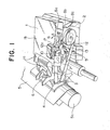
- Fig. 1 shows a state wherein an ink ribbon cassette 1 is mounted on a carriage 2.
- An ink ribbon 3 drawn from the ink ribbon cassette 1 is guided along ribbon guides 4 and is held between a recording sheet 5, wound around a platen 5a, and a printing element (e.g., a daisy wheel) 6.
- the ribbon guides 4 are moved vertically to be set at print, delete, and standby positions, as shown in Fig. 3.
- the ink ribbon cassette 1 has an elongated hole 11 (Fig. 2) engaged with a boss 7 extending from the carriage 2. When the hole 11 is engaged with the boss 7, the cassette 1 is aligned in the left-and-right direction.
- Plate-like fixing ribs 17 extend from two side surfaces of the cassette 1.
- Each fixing pawl 8 has a pressing portion 8a.
- the fixing pawl 8 When the pressing portion 8a is pressed downward, the fixing pawl 8 is pivoted in a direction opposite to the direction of arrow A, against a biasing force of the corresponding coil spring 12, one end of which abuts against a projection 12a, thus disengaging it from the rib 17.
- the fixing pawls 8 also have inclined portions 8b.
- the ribs 17 are guided along the inclined portions 8b and engaged with the corresponding ribs 17 at engaging portions 8c.
- the ink ribbon 3, supplied from a supply roll 18 fitted on a core 19, is wound around a take-up hub 23, axially supported by a take-up lever 22, through ribbons guides 4 and guide bosses la having upper and lower inclined portions.
- a feed gear 24 provided on a take-up knob 10 is rotated by a motor or the like, the ribbon 3 is taken up by the hub 23.
- a spring 25 prevents reverse rotation of the knob 10.
- a detent spring 20 on the supply side applies a resistance force against the rotation of the supply roll 18.
- a tension spring 21 is arranged near an ink ribbon drawing portion of the cassette 1 to apply a given tension force to the drawn ink ribbon 3.
- the tension spring 21 is moved in a direction indicated by arrow B to transfer the bent portion of the ribbon 3 from a distal end 21a of the tension spring 21, which has a small radius of curvature, to the corresponding guide boss la, which has a large radius of curvature.
- the tension spring 21 thus applies the tension force to the ribbon 3 at its distal end 21a. Therefore, when the ink ribbon cassette 1 is disengaged from the carriage 2, the slackened portion of the ribbon 3 is returned to a cassette casing lb and is extended between a pair of guide arms lc to remove the slackening of the ribbon 3.
- only the exposed portion of the ribbon 3 is shifted vertically by the ribbon guides 4, while the cassette casing lb is fixed in position.
- the shift operation requires a variation in length of the exposed ribbon, as shown in Fig. 3, and a variation in the length of the exposed ribbon is absorbed by movement of the distal end 21a of the tension spring 21. Therefore, an appropriate tension force can be applied to the ink ribbon 3 without slackening, regardless of the shift operation.
- the ink ribbon 3 is extended between the guide arms lc while the back surface thereof is supported thereby.
- the guide arms lc have a substantially plate-like shaft. This does not interfere with movement of the ribbon 3 when it is exposed from openings (exit and entrance portions of the casing lb) near the bosses la and is shifted by the ribbon guides 4 in its widthwise direction.
- the ink ribbon cassette 1 When the ink ribbon cassette 1 is to be mounted on the carriage 2, it is pressed downward against biasing forces of the coil spring 12 and a coil spring 14. At this time, the fixing pawls 8 are guided along the inclined portions 8b, and are pivoted in a direction opposite the direction of arrow A, against the biasing force of the coil springs 12. When the pawls 8 are guided to the engaging portions 8c, they are pivoted in the direction of arrow A and engaged with the ribs 17. The cassette 1 is urged against the upper surface of the carriage 2 by the biasing force of the springs 12, one end of each of which abuts against the corresponding pawl 8. The pawls 8 produce a moment about the shafts 13, thus moving the corresponding ribs 17 forward. As shown in Fig. 2, a front wall 15 of the cassette 1 abuts against projections 16 extending from the carriage 2.
- the cassette 1 is thus positioned in the left-and-right direction by engaging the boss 7 on the carriage 2 with the elongated hole 11 formed in the cassette 1.
- the fixing pawls 8 push the ribs 17 forward, and the front wall 15 of the cassette 1 abuts against the projections 16 on the carriage 2, thereby positioning the cassette 1 in the back-and-forth direction.
- the take-up knob 10 Since the take-up knob 10 is positioned at an upper left portion of the recording apparatus, near the boss 7 and the front wall 15 (Fig. 2), it can be accurately meshed with a ribbon rotating shaft 9. This position of the knob 10 also allows a maximum take-up of the ribbon 3 in the limited area of the cassette 1.
- the pressing portions 8a of the fixing pawls 8 are pressed downward.
- the fixing pawls 8 are pivoted in a direction opposite the direction of arrow A, to be separated from the ribs 17.
- the cassette 1 is then popped up by the spring 14 shown in Fig. 3, to be disengaged from the carraige 2.
- the cassette 1 when the cassette 1 is mounted, it need only be urged against the carriage 2 after the ink ribbon 3 is engaged with the ribbon guides 4.
- the pressing portion 8a need only be pressed downward. Therefore, the cassette 1 can be easily mounted on or demounted from the carriage 2, and is fixed thereto with high precision.
- the ink ribbon 3 is moved downward by the ribbon guides 4 to allow easy observation of printed characters at a printing standby position.
- the ribbon 3 is moved upward by the guides 4 to be subjected to printing.
- the ribbon 3 is moved upward to a level higher than that of types.
- Fig. 3 shows the ribbon 3 at the standby and delete positions. As can be seen from Fig. 3, since the ink ribbon 3 is shifted vertically in accordance with the standby, delete, and printing modes and the length of the exposed portion of the ribbon 3 varies, this causes the ribbon 3 to be wound irregularly.
- the ink ribbon 3 can be inclined through a given angle along the inclined portions on the take-up side, allowing it to be wound without being bent at either end or having the ink removed therefrom. At the supply side, transmission of vertical vibration can be prevented, thus similarly preventing bending of the ribbon or removal of the ink.
- the ink ribbon used in the above embodiment can be a one-time ribbon, a correctable ribbon, or one of various other ribbons.
Landscapes
- Impression-Transfer Materials And Handling Thereof (AREA)
Applications Claiming Priority (2)
| Application Number | Priority Date | Filing Date | Title |
|---|---|---|---|
| JP88994/85 | 1985-04-26 | ||
| JP60088994A JPS61248773A (ja) | 1985-04-26 | 1985-04-26 | インクリボンカセツト |
Publications (2)
| Publication Number | Publication Date |
|---|---|
| EP0199355A1 true EP0199355A1 (fr) | 1986-10-29 |
| EP0199355B1 EP0199355B1 (fr) | 1990-11-22 |
Family
ID=13958363
Family Applications (1)
| Application Number | Title | Priority Date | Filing Date |
|---|---|---|---|
| EP86105677A Expired EP0199355B1 (fr) | 1985-04-26 | 1986-04-24 | Cassette de ruban encreur et mécanisme d'alimentation de ruban |
Country Status (4)
| Country | Link |
|---|---|
| US (1) | US4798486A (fr) |
| EP (1) | EP0199355B1 (fr) |
| JP (1) | JPS61248773A (fr) |
| DE (1) | DE3675681D1 (fr) |
Cited By (3)
| Publication number | Priority date | Publication date | Assignee | Title |
|---|---|---|---|---|
| US4798486A (en) * | 1985-04-26 | 1989-01-17 | Canon Kabushiki Kaisha | Ink ribbon cassette having mounting means, slack preventing means and multiple ribbon shifting means |
| EP0341858A1 (fr) * | 1988-05-09 | 1989-11-15 | Ing. C. Olivetti & C., S.p.A. | Cartouche de ruban de correction pour machine à écrire |
| EP0795416A1 (fr) * | 1996-03-12 | 1997-09-17 | Brother Kogyo Kabushiki Kaisha | Cassette à ruban ayant un guide de ruban |
Families Citing this family (9)
| Publication number | Priority date | Publication date | Assignee | Title |
|---|---|---|---|---|
| US4892425A (en) * | 1987-01-09 | 1990-01-09 | Hitachi, Ltd. | Thermal transfer recording apparatus and ink sheet cassette therefor |
| JPH0780337B2 (ja) * | 1989-06-23 | 1995-08-30 | 富士通株式会社 | リボンカセット及びそれを使用したプリンタ |
| US5193919A (en) * | 1989-11-09 | 1993-03-16 | Seiko Epson Corporation | Tape printer |
| JPH0780335B2 (ja) * | 1989-11-20 | 1995-08-30 | 富士通株式会社 | リボンカセット |
| US5098208A (en) * | 1990-01-12 | 1992-03-24 | Smith Corona Corporation | Ribbon cassette with integral paper guide |
| US5441589A (en) * | 1993-06-17 | 1995-08-15 | Taurus Impressions, Inc. | Flat bed daisy wheel hot debossing stamper |
| JP3307090B2 (ja) * | 1994-06-30 | 2002-07-24 | 日立工機株式会社 | 印字装置 |
| TW403053U (en) * | 1995-09-12 | 2000-08-21 | Seiko Epson Corp | Color tape cartridge device of electronic machine |
| JP3700692B2 (ja) * | 2002-09-27 | 2005-09-28 | ブラザー工業株式会社 | リボンカセット |
Citations (5)
| Publication number | Priority date | Publication date | Assignee | Title |
|---|---|---|---|---|
| DE2930127A1 (de) * | 1979-07-25 | 1981-02-19 | Olympia Werke Ag | Schreib- o.ae. bueromaschine mit einer aufnahmevorrichtung fuer eine farbbandkassette |
| EP0042955A1 (fr) * | 1980-06-27 | 1982-01-06 | International Business Machines Corporation | Enrayage du retour pour la bobine enrouleuse dans la cartouche à ruban d'une imprimante |
| GB2091684A (en) * | 1981-01-22 | 1982-08-04 | Scm Corp | A ribbon cartridge handling apparatus |
| DE3106958A1 (de) * | 1981-02-25 | 1982-10-28 | Olympia Werke Ag, 2940 Wilhelmshaven | Auf eine schreib- oder aehnliche bueromaschine aufsetzbare farbbandkassette |
| US4423973A (en) * | 1981-01-17 | 1984-01-03 | Triumph-Adler A.G. Fur Buro- Und Informationstechnik | Ribbon elevating mechanism for ribbon cassettes |
Family Cites Families (28)
| Publication number | Priority date | Publication date | Assignee | Title |
|---|---|---|---|---|
| US3184028A (en) * | 1954-11-30 | 1965-05-18 | Scm Corp | Ribbon feed and reverse mechanism |
| US3604549A (en) * | 1968-07-16 | 1971-09-14 | Ibm | Dual feed rate ribbon mechanism and supply cartridge therefor |
| IT942662B (it) * | 1971-10-04 | 1973-04-02 | Olivetti & Co Spa | Cartuccia per nastro carbonato di una macchina per scrivere calcolatrice contabile o simili macchine per ufficio |
| DE2242141A1 (de) * | 1972-08-26 | 1974-03-14 | Triumph Werke Nuernberg Ag | Vorrichtung zur fuehrung eines karbonfarbbandes an schreib- und aehnlichen maschinen |
| US3941231A (en) * | 1974-07-03 | 1976-03-02 | International Business Machines Corporation | Ribbon cartridge |
| IT1024899B (it) * | 1974-11-25 | 1978-07-20 | Olivetti Ing C S P A | Cartuccia amovibile per un nastro careonato di macchine per scrivere contabili telescriventi e simi li macchine per ufficio |
| US3977512A (en) * | 1975-06-30 | 1976-08-31 | The Singer Company | Ribbon cassette and ribbon advance |
| US4074799A (en) * | 1975-07-17 | 1978-02-21 | Brother Kogyo Kabushiki Kaisha | Ribbon cartridge having slack preventing means |
| US4091914A (en) * | 1977-02-22 | 1978-05-30 | Porelon, Inc. | Wear-activated ribbon reinker |
| DE2717076C3 (de) * | 1977-04-18 | 1981-11-12 | Nixdorf Computer Ag, 4790 Paderborn | Farbbandeinrichtung für Druckwerke |
| US4203677A (en) * | 1977-09-14 | 1980-05-20 | Exxon Research & Engineering Co. | Printer ribbon lift assembly |
| US4401394A (en) * | 1981-10-13 | 1983-08-30 | Xerox Corporation | Universal end of ribbon sensing system |
| US4406553A (en) * | 1981-12-21 | 1983-09-27 | Ncr Corporation | Disposable, snap-in-type ribbon cassette having a resilient ribbon spool mounting arm |
| JPS5959488A (ja) * | 1982-09-30 | 1984-04-05 | Seiko Epson Corp | プリンタのインクリボン装置 |
| JPS59104984A (ja) * | 1982-12-07 | 1984-06-18 | Nec Corp | コレクタブルリボン機構 |
| JPS59109382A (ja) * | 1982-12-16 | 1984-06-25 | Canon Inc | インクリボンカセツト |
| JPS59111883A (ja) * | 1982-12-17 | 1984-06-28 | Canon Inc | インクリボンカセツト装着機構 |
| SE442183B (sv) * | 1983-03-07 | 1985-12-09 | Ericsson Telefon Ab L M | Brytorgan for fergband vid skrivmaskiner och dylikt |
| JPS59194883A (ja) * | 1983-04-20 | 1984-11-05 | Ricoh Co Ltd | リボンスキユ−防止用ガイドロ−ラ |
| JPS59224378A (ja) * | 1983-06-02 | 1984-12-17 | Fujitsu Ltd | プリンタ用インクリボンの送り方法 |
| JPS6064884A (ja) * | 1983-09-20 | 1985-04-13 | Canon Inc | 印字装置 |
| JPS6067948U (ja) * | 1983-10-14 | 1985-05-14 | ブラザー工業株式会社 | 印字リボンカセツト |
| DD219152A1 (de) * | 1983-10-27 | 1985-02-27 | Robotron Bueromasch | Vorrichtung zum befestigen von farbbandkassetten in schreib- oder druckeinrichtungen |
| JPS60104374A (ja) * | 1983-11-11 | 1985-06-08 | Tokyo Electric Co Ltd | 印字装置のキヤリア構造 |
| US4657418A (en) * | 1984-01-16 | 1987-04-14 | Creative Associates | High capacity ribbon supply arrangement |
| JPS59209187A (ja) * | 1984-04-13 | 1984-11-27 | Matsushita Electric Ind Co Ltd | インクリボンカセツトの保持装置 |
| US4624592A (en) * | 1984-06-05 | 1986-11-25 | International Business Machines Corporation | Ribbon cartridge retention |
| JPS61248773A (ja) * | 1985-04-26 | 1986-11-06 | Canon Inc | インクリボンカセツト |
-
1985
- 1985-04-26 JP JP60088994A patent/JPS61248773A/ja active Pending
-
1986
- 1986-04-23 US US06/854,862 patent/US4798486A/en not_active Expired - Lifetime
- 1986-04-24 EP EP86105677A patent/EP0199355B1/fr not_active Expired
- 1986-04-24 DE DE8686105677T patent/DE3675681D1/de not_active Expired - Lifetime
Patent Citations (5)
| Publication number | Priority date | Publication date | Assignee | Title |
|---|---|---|---|---|
| DE2930127A1 (de) * | 1979-07-25 | 1981-02-19 | Olympia Werke Ag | Schreib- o.ae. bueromaschine mit einer aufnahmevorrichtung fuer eine farbbandkassette |
| EP0042955A1 (fr) * | 1980-06-27 | 1982-01-06 | International Business Machines Corporation | Enrayage du retour pour la bobine enrouleuse dans la cartouche à ruban d'une imprimante |
| US4423973A (en) * | 1981-01-17 | 1984-01-03 | Triumph-Adler A.G. Fur Buro- Und Informationstechnik | Ribbon elevating mechanism for ribbon cassettes |
| GB2091684A (en) * | 1981-01-22 | 1982-08-04 | Scm Corp | A ribbon cartridge handling apparatus |
| DE3106958A1 (de) * | 1981-02-25 | 1982-10-28 | Olympia Werke Ag, 2940 Wilhelmshaven | Auf eine schreib- oder aehnliche bueromaschine aufsetzbare farbbandkassette |
Cited By (4)
| Publication number | Priority date | Publication date | Assignee | Title |
|---|---|---|---|---|
| US4798486A (en) * | 1985-04-26 | 1989-01-17 | Canon Kabushiki Kaisha | Ink ribbon cassette having mounting means, slack preventing means and multiple ribbon shifting means |
| EP0341858A1 (fr) * | 1988-05-09 | 1989-11-15 | Ing. C. Olivetti & C., S.p.A. | Cartouche de ruban de correction pour machine à écrire |
| EP0795416A1 (fr) * | 1996-03-12 | 1997-09-17 | Brother Kogyo Kabushiki Kaisha | Cassette à ruban ayant un guide de ruban |
| US5820276A (en) * | 1996-03-12 | 1998-10-13 | Brother Kogyo Kabushiki Kaisha | Ribbon cassette with ribbon guide mechanism |
Also Published As
| Publication number | Publication date |
|---|---|
| US4798486A (en) | 1989-01-17 |
| EP0199355B1 (fr) | 1990-11-22 |
| JPS61248773A (ja) | 1986-11-06 |
| DE3675681D1 (de) | 1991-01-03 |
Similar Documents
| Publication | Publication Date | Title |
|---|---|---|
| US4798486A (en) | Ink ribbon cassette having mounting means, slack preventing means and multiple ribbon shifting means | |
| US4725155A (en) | Ribbon cartridge for a typewriter or similar office machine | |
| US4440514A (en) | Adjustable ribbon feed rates dependent upon ribbon type for ink ribbon cassettes | |
| EP0042031B1 (fr) | Cassette de ruban encreur à emploi unique pour des imprimantes à percussion et imprimante recevant une telle cassette | |
| EP0105472B1 (fr) | Imprimante thermique | |
| US5709485A (en) | Card printer including ink ribbon cartridge with guide shafts | |
| US4867586A (en) | Ink ribbon cassette and loading mechanism therefor | |
| EP0122755B1 (fr) | Cassette à ruban pour machines à écrire | |
| US4908632A (en) | Thermal printing apparatus | |
| EP0260111B1 (fr) | Appareil d'impression | |
| EP0161775A1 (fr) | Mécanisme d'entraînement de ruban encreur | |
| EP0202674B1 (fr) | Cartouche à ruban encreur | |
| EP0131806B1 (fr) | Cartouche d'avancement de ruban | |
| US5033888A (en) | Ribbon guide mechanism for a thermal printer with a ribbon cassette | |
| CA1128890A (fr) | Mecanisme tendeur de ruban | |
| US4533266A (en) | Inked ribbon cartridge for an impact serial printer | |
| US5476330A (en) | Ink ribbon cassette for thermal transfer printer | |
| US4265553A (en) | Ribbon threading assembly for an impact printer | |
| EP0023424A2 (fr) | Elément de support et ensemble d'alimentation pour ruban | |
| EP0004047B1 (fr) | Cartouche pour rubans encreurs | |
| EP0028873A2 (fr) | Dispositif d'alimentation et de mise sous tension du ruban, et imprimante comportant ce dispositif | |
| JP2916240B2 (ja) | プリンタ及びインキリボンをプリンタに装填する方法 | |
| EP0860292B1 (fr) | Imprimante par transfert thermique | |
| EP0535840A1 (fr) | Cylindre d'appui | |
| CA1155077A (fr) | Imprimante a tete de frappe mobile et reserve inerte de ruban encreur |
Legal Events
| Date | Code | Title | Description |
|---|---|---|---|
| PUAI | Public reference made under article 153(3) epc to a published international application that has entered the european phase |
Free format text: ORIGINAL CODE: 0009012 |
|
| AK | Designated contracting states |
Kind code of ref document: A1 Designated state(s): DE FR GB IT |
|
| 17P | Request for examination filed |
Effective date: 19870312 |
|
| 17Q | First examination report despatched |
Effective date: 19880816 |
|
| GRAA | (expected) grant |
Free format text: ORIGINAL CODE: 0009210 |
|
| AK | Designated contracting states |
Kind code of ref document: B1 Designated state(s): DE FR GB IT |
|
| REF | Corresponds to: |
Ref document number: 3675681 Country of ref document: DE Date of ref document: 19910103 |
|
| ITF | It: translation for a ep patent filed | ||
| ET | Fr: translation filed | ||
| ITTA | It: last paid annual fee | ||
| PLBE | No opposition filed within time limit |
Free format text: ORIGINAL CODE: 0009261 |
|
| STAA | Information on the status of an ep patent application or granted ep patent |
Free format text: STATUS: NO OPPOSITION FILED WITHIN TIME LIMIT |
|
| 26N | No opposition filed | ||
| REG | Reference to a national code |
Ref country code: GB Ref legal event code: IF02 |
|
| PGFP | Annual fee paid to national office [announced via postgrant information from national office to epo] |
Ref country code: FR Payment date: 20050408 Year of fee payment: 20 |
|
| PGFP | Annual fee paid to national office [announced via postgrant information from national office to epo] |
Ref country code: GB Payment date: 20050420 Year of fee payment: 20 |
|
| PGFP | Annual fee paid to national office [announced via postgrant information from national office to epo] |
Ref country code: DE Payment date: 20050421 Year of fee payment: 20 |
|
| PGFP | Annual fee paid to national office [announced via postgrant information from national office to epo] |
Ref country code: IT Payment date: 20050430 Year of fee payment: 20 |
|
| PG25 | Lapsed in a contracting state [announced via postgrant information from national office to epo] |
Ref country code: GB Free format text: LAPSE BECAUSE OF EXPIRATION OF PROTECTION Effective date: 20060423 |
|
| REG | Reference to a national code |
Ref country code: GB Ref legal event code: PE20 |